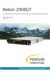
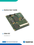
1
MDR-1 12 Ru ugged dized POI PC P Display User Manuaal you RO OTE EC Revisions MDR-12 Revisions Revisions to the User’s Manual are briefly listed here by index: Index Revision Date Author Reason 00 First edit 8.12.2007 P. Walter preliminary version -1- ROTEC technology MDR-12 Instruction Preface The purpose of this manual is to support the user during the installation, application, and modification of the hardware/software described in the following sections. The processes are explained from various technical aspects to simplify the individual steps. In case of problems, it is helpful to try to identify the error in a reproducible way, and to compare the settings of all DIP switches, jumpers, and connector pin assignments, as well as all parameter settings (software), etc., with the specifications in this manual, before you call us. The product you purchased is versatile and complex, and even a small oversight can affect overall performance. Although the information in this document has been carefully reviewed, ROTEC does not warrant it to be free of errors or omissions. In this case, we apologize and would greatly appreciate correction proposals. ROTEC reserves the right to make any changes to the hardware or software to improve functionality or simply operation. These changes will not be documented in all instances. No part of this manual may be reproduced, translated into other languages, or stored in data or word processing systems without the express written permission of ROTEC. © 2008 ROTEC technology GmbH, Rastatt This manual was written and printed by ROTEC technology GmbH Gutenbergstr. 15 * D-76437 Rastatt +49.7222 / 1008-0 Fax +49.7222 / 1008-10 Email: [email protected] http://www.rotec.de ROTEC technology -2- Content MDR-12 Content 1. INSTRUCTION ............................................................................................ 6 2. IMPORTANT SAFETY INFORMATION .......................................................... 7 3. UNPACKING ............................................................................................. 12 4. WALL MOUNTING .................................................................................... 13 5. INTERFACES ............................................................................................. 14 5.1. VIDEO-IN ........................................................................................................................ 14 5.2. PS/2 KEYBOARD .............................................................................................................. 14 5.3. PS/2 MOUSE .................................................................................................................. 14 5.4. SERIAL PORT 1 (COM1) .................................................................................................... 14 5.5. PARALLEL PORT (LPT1)...................................................................................................... 14 5.6. USB .............................................................................................................................. 15 5.7. ETHERNET ....................................................................................................................... 15 5.8. VGA OUTPUT .................................................................................................................. 15 5.9. AUDIO ........................................................................................................................... 16 5.10. CARDBUS ........................................................................................................................ 16 5.11. IDE PORT ....................................................................................................................... 16 5.12. MINI PCI BUS .................................................................................................................. 16 6. OPEN/CLOSE THE HOUSING ..................................................................... 17 7. START UP ................................................................................................. 18 7.1. AMBIENT LIGHT CONTROL ................................................................................................... 18 8. TECHNICAL DATA ..................................................................................... 19 -3- ROTEC technology MDR-12 Instruction 9. PC SPECIFICATIONS .................................................................................. 22 9.1. FUNCTIONAL SPECIFICATIONS ............................................................................................... 22 9.2. BLOCKDIAGRAMM ............................................................................................................. 24 9.3. BIOS OPERATION ............................................................................................................. 25 9.3.1. Determining the BIOS Version................................................................................... 25 9.3.2. Setup Guide ............................................................................................................... 25 9.3.3. Info Menu .................................................................................................................. 27 9.3.4. Main Menu ................................................................................................................ 27 9.3.5. Advanced Menu......................................................................................................... 29 9.3.6. Security Menu ........................................................................................................... 36 9.3.7. Power Menu .............................................................................................................. 37 9.3.8. Boot Menu ................................................................................................................. 39 9.3.9. Exit Menu................................................................................................................... 40 10. DIMMING CONTROL ................................................................................ 41 10.1. GENERAL DESCRIPTION....................................................................................................... 41 10.2. TARGET VALUE BACKLIGHT BRIGTHNESS .................................................................................. 41 10.3. INSTALLATION .................................................................................................................. 42 10.4. START ............................................................................................................................ 42 10.5. SUPERVISION ................................................................................................................... 43 10.5.1. Watchdog .................................................................................................................. 43 10.5.2. Heartbeat................................................................................................................... 43 10.6. PARAMETER FILE ............................................................................................................... 45 10.6.1. Characteristic actual temperatue value .................................................................... 45 10.6.2. Characteristic DA-converter ...................................................................................... 45 ROTEC technology -4- Content MDR-12 10.6.3. Characteristic ambient light / brightness backlight .................................................. 46 10.6.4. Characteristic temperature / brightness backlight ................................................... 46 10.6.5. Backlight power on .................................................................................................... 46 10.6.6. Minimal temperature ................................................................................................ 47 10.6.7. Maximum temperature ............................................................................................. 48 10.6.8. Fan group 1 ................................................................................................................ 48 10.6.9. Fan group 2 ................................................................................................................ 48 10.6.10. Temperature fan group 1 .......................................................................................... 48 10.6.11. Temperature fan group 2 .......................................................................................... 50 10.6.12. Supervisor for application software .......................................................................... 50 10.6.13. Timeout for application software heartbeat............................................................. 50 10.6.14. Watchdog activ .......................................................................................................... 50 10.6.15. Timeout watchdog..................................................................................................... 51 10.6.16. Debug-Mode .............................................................................................................. 51 10.6.17. Debug-Mode SM-Bus ................................................................................................ 51 10.6.18. Host name ................................................................................................................. 51 10.7. MESSAGES ...................................................................................................................... 52 10.7.1. Messages - Commands .............................................................................................. 53 11. MAINTENANCE. ....................................................................................... 55 11.1. CUSTOMER SERVICE ..................................................................................................... 55 11.2. CLEANING .................................................................................................................... 55 12. COMMUNICATIONS REGULATIONS INFORMATION .................................. 55 -5- ROTEC technology MDR-12 1. Instruction Instruction This manual will familiarize you with the installation and use of your Rotec MDR-12 display. Please take the time to read these instructions even if you are familiar with monitors and computers. We have taken all possible care to ensure that this manual contains correct, accurate information. We reserve the right to make changes according to technical progress. However, the manufacturer cannot assume liability for any possible errors. In addition, the manufacturer cannot guarantee that the hardware will meet the purpose you require. We would appreciate reports of any errors, suggestions or criticism. ROTEC technology -6- Important Safety Information 2. MDR-12 Important Safety Information This section contains: • Important safety information • Battery information This display has been tested for conformance to safety regulations and requirements, and has been certified for international use. Like any electronic device, however, the display should be used with care. To protect yourself from possible injury and to minimize the risk of damage to the display, read and follow these safety instructions. General Guidelines • Read all of these instructions. • Save these instructions for later use. • Follow all warnings and instructions marked on the display. • Except as explained elsewhere in this manual, do not attempt to service the display yourself. Opening or removing covers might expose you to dangerous voltage points or other risks. Refer all servicing in marked compartments to service personnel. • If for any reason the cabinet cover needs to be removed, then the instructions given in this manual must be closely followed. Installation Restrictions -7- • Do not use the opened display near water. • Do not place the display on an unstable cart, stand, or table. The display might fall and be seriously damaged. • Do not block or cover the ventilation slots on the cover or cabinet of the display. Air must be allowed to circulate through these slots in order to ensure that the display operates properly and does not overheat. • Install the display near an electrical outlet for ease of access. Use the plug on the power cord as the power disconnect device for the display. When your display is switched off, be aware that it still carries full line voltage, and consumes some electrical energy. To completely remove all voltages from the display and the auxiliary outlet, you must unplug the power cable from the wall outlet. • Do not place the display near or over a radiator or heat register or in direct sunlight. Place the display in a small enclosure only if providing proper ventilation. • To prevent fire, never place any type of candle or flames on the top or near the display. ROTEC technology MDR-12 Important Safety Information • Do not permit anything to rest on the power cord. Do not locate the display where people can walk on its power cord. • Do not plug the display into the same circuit with radio or television receivers. ROTEC technology -8- Important Safety Information MDR-12 Electrical Restrictions • Use the plug that is provided with the display. If you are unable to insert the plug into the outlet, contact your electrician to replace your obsolete outlet. Do not defeat the safety purpose of the grounding-type plug. • For international installation with a power source of 88-264 VAC, use a minimum 0.75 mm2 PVC sheathed three-core flexible cord, type H05VV-F3G, with a green/yellow protective earthing conductor electrically connected to the protective earthing terminal within the equipment and connected to the protective earthing contact of the plug. The cable set should have safety approvals for the international installation and be marked HAR. • For plugged equipment, the socket-outlet shall be installed near the equipment and shall be easily accessible. • Operate the display from the type of power source indicated on the marking label. If you are unsure of the type of power available, consult your dealer or local power company. • When your display is switched off, be aware that it still carries full line voltage. To completely remove all voltages from the display, you must unplug the power cable from the wall outlet. Operating and Maintenance Guidelines • Keep the area around the display free from static electricity and magnetic fields. Before you touch the display, discharge static electricity on your body by touching a metallic surface. • Operate the display only when the cover is in the closed position. • Do not turn the display on and off in rapid succession. Doing so might damage the configuration files and other data on the hard disk. • Adjust only those controls that are covered by the operating instructions. Improper adjustment of other controls might result in damage and often requires extensive work by a qualified technician to restore the product to normal operation. • Unplug the display and the monitor from the electrical outlet before cleaning. Clean the display and the monitor periodically with a damp cloth. • Prepare the display before moving it by taking the following actions: • -9- - Disconnect the display and the monitor from the wall outlet. - Close the cabinet. - Disconnect external peripheral devices. Unplug the display from the wall outlet and refer servicing to qualified service personnel under any of the following conditions: - The cord or plug is damaged or frayed. - The display does not operate normally when the operating instructions are followed. - The display has been dropped or the cabinet has been damaged. - The display exhibits a distinct change in performance, indicating a need for service. ROTEC technology MDR-12 Important Safety Information • The LCD panel used in this product is made of glass. Therefore, it can break when the product is dropped or applied with impact. Be careful not to be injured by broken glass pieces in case the LCD panel breaks. The LCD panel is a very high technology product giving you fine picture details. Occasionally, a few non-active pixels may appear on the screen as a fixed point of blue, green or red. • When the MDR display is operated continuously for long hours, the residual image of a previous image may be observed. If a fixed image is displayed for a long period, this residual image may be observed permanently (image sticking). In order to prevent the fast development of image sticking, the following recommendations are suggested: - A fixed image should not be displayed for a long period; the image should be changed to other images with short cycles. - When the MDR display is not in use, please turn off the display. - When the MDR display is in idle, please use moving screen saver. Battery Information If the display has a battery that can be changed by the user, observe the following warning whenever you are handling the battery: Warning! Danger of explosion if battery is incorrectly replaced. The battery used in this device may present a fire or chemical burn hazard if mistreated. Do not recharge, disassemble, heat above 100°C (212°F), or incinerate. Do not expose the contents of the battery cells to water. Replace the battery with an approved battery only. Approved replacement batteries are available from your supplier. Use of another battery may present a risk of fire or explosion. Dispose of the old battery according to local recycling regulations. Note: Do not dispose batteries. Please return batteries to your supplier to ensure recycling and disposal according to the legal regulations. Note: The batteries used for timer backup or similar purposes, do not contain cadmium or mercury compounds. ROTEC technology - 10 - Important Safety Information - 11 - MDR-12 ROTEC technology MDR-12 3. Unpacking Unpacking Carefully take the display out of the packaging and make sure that all of the following components are included: - MDR-12 - AC-Power Adapter (optional) - This user manual - Windows XP licence including CD (optional) ROTEC technology - 12 - Wall mounting 4. MDR-12 Wall mounting The Rotec MDR display can be mounted and operated in vertical or in horizontal position. That means that you can hang the display either in “landscape” or in “portrait” orientation to the wall. The displayed picture can also be rotated to fit the desired orientation. Attention: For proper function of the display’s cooling system it is necessary that the distance of the backside of the display to the wall is minimum 20 mm (not necessary in case of fanless operation). • Mount a mounting adapter with VESA 75/75 described in the manual of the mouning kit - 13 - ROTEC technology MDR-12 Interfaces 5. Interfaces 5.1. Video-In The Video-In Interface is realized using a Conexant CX23883 PCI Video Decoder, that provides depending on configuration four FBAS signal inputs (multiplexed on one A/D-Converter) or three FBAS and one S-Video input. Note: The Video-In ist not available on the light version 5.2. PS/2 Keyboard The keyboard uses I/O and IRQ resources. The BIOS allocates the resources during POST configuration. The resources are set to be compatible with common PC/AT settings. Use the BIOS setup to change some keyboard-related parameters. 5.3. PS/2 Mouse The mouse uses I/O and IRQ resources. The BIOS allocates the resources during POST configuration. The resources are set to be compatible with common PC/AT settings. You can change some mouse-related parameters from the BIOS setup. 5.4. Serial Port 1 (COM1) The serial-communication interface uses I/O and IRQ resources. The resources are allocated by the BIOS during POST configuration and are set to be compatible with common PC/AT settings. Use the BIOS setup to change some parameters that relate to the serial-communication interface. 5.5. Parallel Port (LPT1) The parallel-communication interface uses I/O, IRQ, and DMA resources. The resources are allocated by the BIOS during POST configuration and are set to be compatible with common PC/AT settings. You can change some parameters of the parallel-communication interface through the BIOS setup. ROTEC technology - 14 - Interfaces 5.6. MDR-12 USB Three USB host controllers are on the Intel® 82801DB south bridge device. The USB controllers comply with both versions 1.1 and 2.0 of the USB standard and are backward compatible. Only two ports are available. The USB controllers are PCI bus devices. The BIOS allocates required system resources during configuration of the PCI bus. 5.7. Ethernet The Ethernet interface is based on the Intel® 82562 Fast Ethernet PCI controller. This 32-bit PCI controller is a fully integrated 10/100BASE-TX LAN solution. The Ethernet interface requires an external transformer. The Ethernet interface is a PCI device. The BIOS setup automatically configures it during configuration of the PCI device. 5.8. VGA Output The MDR12 graphics subsystem is integrated in the Intel® 852GM/855GME northbridge. It has the following features: • Display image rotation • Graphics core frequency up to 250 MHz • Display core frequency at 133 MHz, 200 MHz or 250 MHz • Render core frequency at 100 MHz, 133 MHz, 166 MHz, 200 MHz, 250 MHz • 2D graphics engine • Improved hardware motion compensation for MPEG2 • Software DVD at 60 Fields/second and 30 frames/second full screen • Support for standard definition DVD (i.e. NTSC pixel resolution of 720x480, etc.) quality encoding at low CPU utilization • Single- or dual-channel LVDS panel support up to UXGA panel resolution with frequency range from 25 MHz to 112 MHz (single channel/dual channel) • 3D graphics engine • 3D setup and render engine • Zone rendering • High quality performance texture engine • Viewpoint transform and perspective divide • It can drive cathode ray tube (CRT) monitors and flat-panel displays. You can program the graphics controller to use up the 32MB of unified memory architecture (UMA) memory as its video memory. Additional memory may be assigned by the Intel Graphics Driver - 15 - ROTEC technology MDR-12 Interfaces • Max. resolution CRT QXGA 2048x1536 • Max. resolution LCD UXGA 1600x1200 (4G colors) • Bits/Pixels supported 1x18 bit, 2x18 bit, 1x24 bit* , 2x24 bit 5.9. ) Audio The MDR audio controller is integrated in the Intel® 82801DB southbridge, the external audio codec is a AC97 compatible VIA VT1618 . The audio controller is a PCI bus device. The BIOS allocates required system resources during configuration of the PCI device. 5.10. Cardbus The Cardbus controller supports PCMCIA (16 Bit) and PC-Card (32 Bit) devices. 5.11. IDE Port The IDE host adapter is capable of UDMA operation. Please refer to the IDE specifications documents for additional information. Primary and secondary IDE host adapters are PCI bus devices. They are configured by the BIOS during PCI device configuration. You can disable them in setup. Resources used by the primary and secondary IDE host adapters are compatible with the PC/AT. 5.12. Mini PCI Bus The implementation of this subsystem complies with the miniPCI specification. Refer to the documentation for additional information. ROTEC technology - 16 - Open/close the housing 6. MDR-12 Open/close the housing Warning! Take care that power is off while doing some handlings in the open housing. - 17 - ROTEC technology MDR-12 7. Start Up Start Up The MDR will start up by connecting the power cable to the power connector on the rear side. Take care that the cable is supplied with power. The MDR will boot up the built-in PC. 7.1. Ambient Light Control The brightness of the display is controlled with an ambient light sensor, which is behind the little hole at the top of the front. The characteristics can be programmed. See section 10. ROTEC technology - 18 - Technical Data 8. MDR-12 Technical Data Product LCD Module Size MDR-12 12,1“ Visual Characteristics 800x600 Panel Resolution 1024x768 (optional) Response time Tg = 6,5ms Contrast ratio 600:1 Brightness 400 cd/m² Standard Input/Output Capabilities Video (S-Video, Composite) Standard VGA Output optional Yes Control IR Remote Control over RS232 no Yes / Additional Software Required Controled parameters - backlight brightness Yes - backlight on/off Yes Software upgrade Yes Watchdog Yes Ambient Light Sensing Yes Over Heating Protection - 19 - Yes (Option) ROTEC technology MDR-12 Technical Data Other Specifications Protective Glass Cover Yes, Anti-glare Embedded PC Yes System for 24H/7D usage Yes Operating Temperature Range Product Warranty -10 to 60 degree Celsius at 10-90% Hum. 18 months from the delivery date (Return To Base) Embedded PC Specification Celeron 600 MHz CPU Performance Celeron 1 GHz Memory 256MB RAM (up to 1 Gbyte optional) LAN 10/100 Base-T USB 2x USB 2.0 Serial Ports 1x RS-232 Parallel LVDS IDE Sound Audio 1x LPT (Optional) 1x LVDS, 2ch, 24 Bit 2x enhanced IDE-Ports, SATA AC’ 97 Hard Disk 40GB Mass Storage CFC-Card slot Operating System Windows XP Power Supply Input Voltage [V] 8-28 VDC Input Current [A] Ca. 900 mA Inrush Current [A] tbd ROTEC technology - 20 - Technical Data MDR-12 Mechanical Specification Fan with minimal noise No Security Yes Housing Aluminium with Powder Coating Size of Monitor (WxHxD) 310x250x52 Size of Packaging (WxHxD) 400x300x100 Weight of Monitor with Protection Glass (NET) 3 Kg Weight including Packaging (Cross) 4 kg Mounting Fixation Points on the back of the monitor Landscape or Portrait mode use Vesa 75 Yes Classification Classification CE, UL and FCC certified - 21 - IP54 Compliant CE, FCC, prepared for UL ROTEC technology MDR-12 PC Specifications 9. PC Specifications 9.1. Functional Specifications Prozessor • • Intel® Pentium® M Processor 1.4 GHz Intel® Celeron® M Processor 600 MHz and 1.0 GHz Bus • • 400 MHz CPU bus 200/266 MHz memory bus Chipset: Intel® 852GM (Celeron M 600MHz), 855GME (others) Super I/O: Winbond W83627HG connected by LPC interface Cache: On-die Second level 2 MB(1.4 GHz) 512 kB (Celeron M 600 MHz, 1.0 GHz) Memory • • One 200-pin DDR-SO-DIMM 2.5V PC-1600/2100 unbuffered DDR-SDRAM, up to 1GB Two Serial Ports (COM1 and COM2) • • • Transistor-to-transistor (TTL) signals only Standard RS232C 16550 compatible Infrared Device Association (IrDA) interface One Parallel Port (LPT1) • Enhanced Parallel Port (EPP) and Extended Capabilities Port (ECP) with bi-directional capability Floppy • 3.5” standard drive via Flex Foil adapter Enhanced Intelligent Drive Electronics (EIDE): Two Peripheral Component Interconnect (PCI) Bus Master IDE ports (up to three devices) support • • • Ultra Direct Memory Access (DMA) mode Programmed Input/Output (PIO) modes up to Mode 4 timing Multiword DMA Mode 0,1,2 with independent timing ROTEC technology - 22 - PC Specifications MDR-12 Universal Serial Bus (USB) • • • Three USB 1.1/2.0 ports (UHCI and EHCI) USB legacy keyboard support USB floppy, CD-ROM, Hard drive, and Memory stick boot support Integrated Ethernet: Intel 82562 10/100 Mbps Fast Ethernet controller • Integrated, WfM 2.0 and IEEE 802.3 compliant; 10BASE-T and 100BASE-TX compatible PHY Onboard video graphics array (VGA): Integrated in Intel 852GM/855GME • Graphics memory controller hub with Intel Extreme Graphics 2 technology • Up to 64 MB Video RAM (UMA) • Cathode ray tube (CRT) and low voltage differential signaling (LVDS) liquid-crystal dis- play (LCD) interfaces Audio: Integrated in Intel 82801DB southbridge • AC97, Windows Sound System™ compatible Video In • Conexant Video Broadcast decoder CX23883 BIOS: Phoenix, 1MB Flash-BIOS in Firmware Hub Flash Memory • NV-EEPROM for CMOS-setup retention without battery PS/2 keyboard controller PS/2 mouse interface Watchdog timer (WDT) integrated in the Super I/O (Winbond 83627HG) Real-time clock (requires external battery) Power Management • • - 23 - ACPI support Suspend to RAM (S3) support ROTEC technology MDR-12 9.2. PC Specifications Blockdiagramm ROTEC technology - 24 - PC Specifications 9.3. MDR-12 BIOS Operation The CPU is equipped with a Phoenix BIOS, which is located in an onboard Flash EEPROM. The device has 8-bit access. Faster access (16 bit) is provided by the shadow RAM feature. You can update the BIOS using a Flash utility. 9.3.1. Determining the BIOS Version To determine the PhoenixBIOS version, immediately press the Pause key on your keyboard as soon as you see the following text display in the upper left corner of your screen: 9.3.2. Setup Guide PhoenixBIOS 4.0 Release 6.1 Copyright 1985-2006 Phoenix Technology Ltd.All Rights ReservedKontron® BIOS Version <ePanel PM/CM R110>© Copyright 20022007 Kontron Embedded Modules GmbH The PhoenixBIOS Setup Utility changes system behavior by modifying the BIOS configuration. The setup program uses a number of menus to make changes and turn features on or off. 9.3.2.1. Start Phoenix BIOS Setup Utility To start the PhoenixBIOS setup utility, press <F2> when the following string appears during bootup. Press <F2> to enter Setup The Info Menu then appears. The Setup Screen is composed of several sections: Setup Screen Location Menu Bar Top Legend Bar Bottom Item Specific Help Window Right Menu Window Left Center General Help Window Overlay (center) Function Lists and selects all top level menus. Lists setup navigation keys. Help for selected item. Selection fields for current menu. Help for selected menu. Menu Bar The menu bar at the top of the window lists different menus. Use the left/right arrow keys to make a selection. Legend Bar Use the keys listed in the legend bar on the bottom to make your selections or exit the current menu. The table below describes the legend keys and their alternates. - 25 - ROTEC technology MDR-12 PC Specifications Key <F1> or <Alt-H> <Esc> ← or → Arrow key ↑ or ↓ Arrow key <Tab> or <Shift-Tab> Function General Help window. Exit menu. Select a menu. Select fields in current menu. Cycle cursor up and down. <Home> or <End> Move cursor to top or bottom of current window. <PgUp> or <PgDn> Move cursor to next or previous page. <F5> or <-> <F6> or <+> or <Space> Select previous value for the current field. Select next value for the current field. <F9> Load the default configuration values for this menu. <F10> Save and exit. <Enter> Execute command or select submenu. <Alt-R> Refresh screen. Selecting an Item Use the or the key to move the cursor to the field you want. Then use the + and – keys to select a value for that field. To Save Value commands in the Exit menu save the values displayed in all the menus. Displaying Submenus Use the or submenus key to move the cursor to the submenu you want. Then press <Enter>. A pointer ( ) marks all Item Specific Help Window The Help window on the right side of each menu displays the Help text for the selected item. It updates as you move the cursor to each field. General Help Window Pressinf <F1> or <ALT-F1> on a menu brings up the General Help window that describes the legend keysand their alternates. Press <Esc> to exit the Genral Help window. ROTEC technology - 26 - PC Specifications 9.3.3. MDR-12 Info Menu This screen shows a set of informational items, which might be handy e.g. in case you need some kind of support. 9.3.4. Main Menu Feature System Time System Date Legacy Diskette A 8Compact Flash 8Secondary Master 8Secondary Slave Smart Device Monitoring - 27 - Option HH:MM:SS MM/DD/YYYY 360 kB, 5 ¼ “ 1.2 MB, 5 ¼ “ 720 kB, 3 ½ “ 1.44/1.25 MB, 3 ½ “ 2.88 MB, 3 ½ “ Disabled Autodetected drive Description Set system time. Use <Enter to move to MM or SS. Set system date. Use <Enter to move to DD or YYYY. Select floppy type. Note that 1.25 MB 3 ½ “ references a 1024 byte/sector Japanese media format. The 1.25 MB 3 ½ “ diskette requires a 3-Mode floppy-disk drive. Displays result of PM autotyping. Autodetected drive Displays result of SM autotyping. Autodetected drive Disabled Enabled Displays result of SS autotyping. IDE Failure Prediction.Turns on Self-Monitoring Analysis-Reporting Technology, which monitors the condition of the hard drive and reports when a catastrophic IDE failure is about to happen. ROTEC technology MDR-12 PC Specifications 9.3.4.1. Master or Slave Submenus Feature Option Type None IDE Removable ATAPI Removable CDROM Other ATAPI User Auto Cylinders 1 to 65,536 Description None = Autotyping is not able to supply the drive type or end user has selected None, disabling any drive that may be installed. User = You enter parameters of hard-disk drive installed at this connection. Auto = Autotypes hard-disk drive installed here. CD-ROM = A CD-ROM drive is installed here. ATAPI Removable = Removable disk drive is installed here. Number of cylinders. Heads 1 to 256 Number of read/write heads. Sectors 1 to 63 Number of sectors per track. Maximum Capacity N/A Displays the calculated size of the drive in CHS Total Sectors N/A Number of total sectors in LBA mode Maximum Capacity Multi-Sector Transfer N/A Disabled 2 sectors 4 sectors 8 sectors 16 sectors LBA Mode Control 32-Bit I/O Disabled Enabled Disabled Enabled Transfer Mode Standard Fast PIO 1 Fast PIO 2 Fast PIO 3 Fast PIO 4 FPIO 3/ DMA 1 FPIO 4/ DMA 2 Ultra DMA Mode Disabled Mode 0 Mode 1 Mode 2 Mode 3 Mode 4 Mode 5 SMART Device Monitoring Hard Disk Pre-Delay Disabled Enabled Disabled 3 Seconds 6 Seconds 9 Seconds 12 Seconds 15 Seconds 21 Seconds 30 Seconds Displays the calculated size of the drive in LBA Any selection except Disabled determines the number of sectors transferred per block. Standard is 1 sector per block. Enabling LBA causes Logical Block Addressing to be used in place of CHS. Enables 32-bit communication between CPU and IDE card. Requires PCI or Local Bus. Selects the method for transferring the data between the hard disk and system memory. Selects the UDMA mode used for moving data to/from the drive. Autotype the drive to select the optimum transfer mode. Shows if SMART Device monitoring is supported by the drive. Adds a delay before the first access of a hard disk by the BIOS. Some hard disks hang if accessed before they have initialized themselves. This delay ensures the hard disk has initialized after power up, prior to being accessed. 9.3.5. ROTEC technology - 28 - PC Specifications MDR-12 Advanced Menu Feature Option Description 8Advanced Chipset Control sub menu Opens Advanced Chipset Control sub menu. 8PCI/PNP Configuration sub menu Opens PCI/PNP Config sub menu. 8Memory Cache sub menu Opens Cache Control sub menu. 8I/O Device Configuration sub menu Opens Peripheral Config sub menu. 8Keyboard Features sub menu Opens Keyboard Features sub menu. 8Hardware Monitor sub menu Shows hardware monitor current state. 8Watchdog Settings sub menu Opens Watchdog Config sub menu. 8Display Control sub menu Opens Display Control sub menu 8Miscellaneous sub menu Opens sub menu with miscellaneous options. 9.3.5.1. Advanced Chipset Control Submenu Feature Option Description 1MB 8MB 16MB 32MB Select the amount of main memory that the Internal Graphics Device will use. Max. suported Mem Freq DDR200 DDR266 DDR333 Use this node to limit the supported memory frequencies. Serial Interrupt Mode Quiet Continuous Sets the mode for the Serial Irq, Continuous mode is advisable with high interrupt traffic on the Serial IRQ line. This inclues all ISA, LPC and SIO devices Graphic Memory - 29 - ROTEC technology MDR-12 PC Specifications 9.3.5.2. PCI/PNP Configuration Submenu Feature Option Description PnP OS installed No Yes Select the operating system installed on your system which you will use most commonly. If your system has a PnP OS (e.g. Win9x) select Yes to let the OS configure PnP devices not required for booting. No allows the BIOS to configure them. Note: An incorrect setting can cause some operating systems to display unexpected be- haviour. Reset Configuration Data No Yes Yes erases all configuration data in ESCD, which stores the configuration settings for plug-in devices. Select Yes when required to restore the manufacturer’s defaults. Secured Setup Configuration 8PCI Device, miniPCI Slot CardBus Controller miniPCI Slot IRQ line Onboard LAN IRQ line Onboard USB EHCI IRQ line Assign IRQ to SMB Yes No Yes prevents a Plug and Play OS from changing system settings. sub menu Enabled Disabled Opens sub menu to configure miniPCI device Disabled Auto IRQ3, 4, 5, 7, 9, 10, 11, 12, 14,15 PCI devices can use hardware interrupts called IRQ´s. A PCI device cannot use IRQ´s already in use by PCMCIA devices. see above see above see above Disabled Enabled see above Enable/Disable the Slot. Setting item to "Disabled" will remove the Slot from PCI Config Space. Determines whether the onchip SMBus host controller gets an IRQ assigned. 9.3.5.3. PCI Device, miniPCI Slot Submenu Feature Option Description Enable Slot Enabled Disabled Option ROM Scan Disabled Enabled Enable/Disable the Slot. Setting item to "Disabled" will remove the Slot from PCI Config Space. Initialize device expansion ROM. Enable Master Latency Timer Disabled Enabled Default 20h, 40h, 60h, 80h, A0h, C0h, E0h Enables device in slot as a PCI bus master, not every device can function as a master. Check device documentation. Minimum guaranteed time slice allocated for bus master in units of PCI bus clocks. A high-priority, high-throughput device may benefit from a greater value. 9.3.5.4. ROTEC technology - 30 - PC Specifications MDR-12 Memory Cache Submenu Feature Memory Cache Option Disabled Enabled Description Enables or Disables the L2 cache. Cache System BIOS area Uncached Write Protect Cache Video BIOS area Uncached Write Protect Uncached Write Through Write Protect Write Back Controls caching of Video BIOS area. Cache Base 512 – 640k Uncached Write Through Write Protect Write Back Controls caching of 512k – 640k base memory. Cache Extended Base / Extended Memory area: Uncached Write Through Write Protected Write Back Controls caching of system memory below 640k / above 1MB. D000 – D3FF D400 – D7FF D800 – DBFF DC00 – DFFF Disabled Write Through Write Protected Write Back Disabled: block is not cached. Write Through: Writes are cached and sent to main memory at once. Write Protect: Writes are ignored. Write Back: Writes are cached, but not sent to main memory until necessary. Cache Base 0 – 512k Controls caching of System BIOS area. Controls caching of 512k base memory. 9.3.5.5. I/O Device Configuration Submenu Feature Option Description Local Bus IDE adapter Disabled Primary Secondary Both Enables the integrated local bus IDE device. 8USB Options AC97 Audio Controller sub menu Disabled Enabled USB Configuration Enable the AC97 Audio device. This Setup Item will have no effect if an AC97 Audio MDC is not present. 8LAN Options sub menu LAN Configuration 8SIO Options sub menu SIO Configuration 9.3.5.5.1. - 31 - ROTEC technology MDR-12 PC Specifications USB Options Submenu Feature USB UHCI Host Controller 1 USB UHCI Host Controller 2 USB touch Controller USB EHCI Host Controller * Legacy USB Support EHCI Legacy Support Option Description Enabled Disabled Enabled Disabled Enabled Disabled Disabled Enabled Disabled Enabled Disabled Enabled Enable/ Disable UHCI 1 HC = USB ports 0 and 1. Enable/ Disable UHCI 2 HC = USB ports 2 and 3. Enable/ Disable USB touch Controller. Controls USB 2.0 functionality.* Enable support for USB keyboard and mice and boot from USB mass storage devices. This Enables EHCI Legacy Support, Disable this if you have a OS that doen't have either acpi support or an EHCI driver(not an USB2 driver) installed. 9.3.5.5.2. LAN Options Submenu Feature LAN MAC address (ETH1) Onboard LAN Controller Onboard LAN PXE ROM Enable WOL Option Description Disabled Enabled Shows MAC address Enables the ICH4 internal LAN controller. Setting item to 'Disabled' will remove the LAN from PCI config space. Disabled Enabled OS control Enabled Disabled Enables the remote boot BIOS extension for the onboard LAN controller. This item controls the activation of the PME line which can be used to wake the system via LAN. 'OS control' means that BIOS won't interfere with the settings made in an ACPI OS. 9.3.5.5.3. SIO Options Submenu Feature Onboard FDC Option Disabled Enabled Description Enables the onboard FDC controller. Serial port A Serial port B Disabled (port B) Enabled Auto (port A) Disabled turns off the port. Enabled requires end user to enter the base I/O ad- dress and the IRQ. Auto makes the BIOS configure the port. *Onboard LPT Disabled Enabled Auto OS Controlled Disabled turns off the port. Enabled requires end user to enter the base I/O ad- dress and the IRQ. Auto makes the BIOS configure the port. *Mode Output only Bidirectional EPP ECP Set the mode for the parallel port. ROTEC technology - 32 - PC Specifications MDR-12 9.3.5.6. - 33 - ROTEC technology MDR-12 PC Specifications Keyboard Features Submenu Feature Option Description Numlock Auto On Off On or Off turns NumLock on or off at bootup. Auto turns NumLock on if it finds a numeric key pad. Key Click Disabled Enabled 30/sec,26.7/sec, 21.8/sec, 13.3/sec, 10/sec, 6/sec, 2/sec Turns audible key click on. Keyboard auto-repeat delay ¼ sec, ½ sec, ¾ sec, 1 sec Sets delay time after the key is held down before it begins to repeat the keystroke. PS2 Scanner Workaround Disabled Enabled This is a workaround for some PS2 scanners that require to be enabled after a reset. Keyboard auto-repeat rate Sets number of times to repeat a keystroke per second if you hold the key down. 9.3.5.7. Hardware Monitor Submenu This submenu shows the current voltages and temperatures of the system. Vcc (3.3V) Voltage 3.3V power plane CPU Core Voltage Core voltage (depends on CPU) 5Vsb Voltage 5V Standby plane Battery Voltage Backup battery voltage CPU Temperature CPU Fan Speed Temperature of CPU die Speed of CPU Fan 9.3.5.8. Watchdog Settings Submenu Feature Option Mode Disabled Reset NMI Description Delay 1s, 5s, 10s, 30s, 1min, 5.5min, 10.5min, 30.5min The time until the watchdog counter starts counting. Useful to handle longer boot times. Timeout 1s, 5s, 10s, 30s, 1min, 5.5min, 10.5min, 30.5min Maximum trigger period. Select watchdog operation mode. 9.3.5.9. ROTEC technology - 34 - PC Specifications MDR-12 Display Control Submenu Feature Display Mode JDA Revision Flat Panel Type Flat Panel Scaling Flat Panel backlight Option Description CRT only LFP only CRT+LFP Select the display mode. 1.4 VGA 1x18 SVGA 1x18 XGA 1x18 XGA 1x24 XGA 2x18 SXGA 2x24 UXGA 2x18 Enter PAID Enter FPID Auto Displays the revision of the data area image. Select Auto to let the BIOS automatically detect the panel type or use one of the predefined fixed panel types. Centered Stretched 0 – 255 128 Stretched expands a low resolution video mode to full screen on a higher flat panel resolution. Adjust level of backlight brightness 9.3.5.10. Miscellaneous Submenu Feature Option Description Floppy Check Disabled Enabled Enabled verifies floppy type on boot; disabled speeds boot. Summary Screen Disabled Enabled If enabled, a summary screen is displayed just before booting the OS to let the end user see the system configuration. QuickBoot Mode Disabled Enabled Normal Just zero it None Allows the system to skip certain tests while booting. This will decrease the time needed to boot the system. Determines which type of tests will be performed on memory above 1MB. The option Normal is not visible if QuickBoot is enabled. Disabled Enabled If enabled, system comes up with a blank screen instead of the diagnostic screen during bootup. Determines if post errors cause the system to halt. Extended Memory Testing Dark Boot Halt On Errors PS/2 Mouse Yes No Autodetect Enabled Disabled Selecting Disabled prevents any installed PS/2 mouse from functioning, but frees up IRQ12. Selecting Autodetect frees IRQ12 if no mouse was detected. Large Disk Access Mode DOS Other Select DOS if you have DOS. Select Other if you have another OS such as UNIX. A large disk is one that has more than 1024 cylinders, more than 16 heads or more than 63 sectors per track. Spread Spectrum Disabled Enabled Controls the spread spectrum feature of the clock generator. 9.3.6. - 35 - ROTEC technology MDR-12 PC Specifications Security Menu Feature Option Description Set User Password Up to seven alphanumeric characters Pressing <Enter> displays the dialog box for entering the user password. In related systems, this password gives restricted access to setup. Set Supervisor Password Up to seven alphanumeric characters Pressing <Enter> displays the dialog box for entering the user password. In related systems, this password gives full access to setup. Diskette access User Supervisor Fixed disk boot sector Normal Write protected Virus check reminder System backup reminder Disabled Daily Weekly Monthly Password on boot Disabled Enabled Enabled requires supervisor password to access floppy disk. Write protect the boot sector on the hard disk for virus protection. Requires a password to format or Fdisk the hard disk. Displays a message during bootup asking (Y/N) if you backed up the system or scanned for viruses. Message returns on each boot until you respond with 'Y'. Daily displays the message on the first boot of the day, Weekly on the first boot after Sunday, and Monthly on the first boot of the month. Enables password entry on boot. 9.3.7. ROTEC technology - 36 - PC Specifications MDR-12 Power Menu A power management system reduces the amount of energy used after specified periods of inactivity. Use the Advanced Options menu to specify whether an activity can terminate a Standby or Suspend state and restore Full On. Feature Option Description Enable ACPI No Yes Enables/Disables ACPI BIOS (Advanced Configuration and Power Interface). IRQ9 is used for SCI (System Control Interrupt). Do not use for ISA bus devices. ACPI Control sub menu These items will control selective functionality when an ACPI OS is loaded. Thermal Management Power Savings Hard Disk Timeout Auto Suspend Timeout Resume on Modem Ring Resume on Time Resume Time Power Supply Power Button Function sub menu Disabled Customized Maximum Power Saving Maximum Performance Disabled, 10 sec – 15 min Off, 5min, 10min, 15min, 20min, 30min, 40min, 60min Off On Off On 00:00:00 ATX AT Power Off Sleep Maximum options select predefined values. Select Customized to make your own selections from the following fields. Disabled turns off all power management. Inactivity period of hard disk required before standby (motor off). Inactivity period required after Standby to Suspend mode (maximum power shutdown). Enabled wakes the system on incoming calls detected by modem (RI). Enabled wakes the system at a specific time. Specify the time when the system is to wake up. <Tab>, <Shift-Tab> or <Enter> selects field. Choose the connected power supply, ATX or AT. Determines if the system enters suspend or soft off when the power button is pressed. 9.3.7.1. - 37 - ROTEC technology MDR-12 PC Specifications ACPI Control sub menu Feature Option APIC – IO APIC Mode Disabled Enabled Native IDE Support Disabled Enabled Deepest sleep state for standby None S1 S3 Description This item is valid only for Windows XP. Also, a fresh install of the OS must occur when APIC Mode is desired. Test the IO APIC by setting an item to Enabled. The APIC Table will then be pointed to by the RSDT, the Local APIC will be initialized, and the proper enable bits will be set in IHC4M. Enable Native IDE support for WINXP by setting this item. The NATA Package will be created if this item is set to Enabled. Changing this item will have no effect in WIN98, WINME, or WIN2K. This option chooses S3 saves more power than S1 and choosing 'None'will disable standby in the OS. Please be sure your board supports the appropriate Sleep state when making this choice. S3/S1 offers the OS the 9.3.7.2. Thermal Management sub menu Feature Option Description * Automatic Thermal Monitor Control Circuit Disabled TM1 TM2 Enables the thermal control circuit (TCC) of the thermal monitor feature of the Pentium-M CPU. TM1 = 50% duty cycle TM2 = Geyserville III Automatic TTC must be enabled to ensure that the processor operates within specification. Passive Cooling Trip Point Disabled 40 C – 100 C Determines the temperature of the ACPI Passive Trip Point, the point at which the OS will turn on/off CPU clock throttling. Passive TC1 Value 1, 2, 3, …15, 16 Determines the TC1 (temperature coefficient 1) value for the ACPI passive cooling formula. Passive TC2 Value 1, 2, 3, 4, 5, …15, 16 Determines the TC2 (temperature coefficient 2) value for the ACPI passive cooling formula. Passive TSP Value 2, 4, 6, 8, 10, … 28, 30 Critical Trip Point 40 C – 110 C 100 Determines the Tsp (sampling period) value for the ACPI passive cooling formula. This value controls the temperature of the ACPI Critical Trip Point- the point at which the OS will shut the system off. Active Trip Point Disabled 40 C – 100 C °C Determines the temperature of the ACPI Active Trip Point, the point at which the OS will turn on/off the CPU fan. 9.3.8. ROTEC technology - 38 - PC Specifications MDR-12 Boot Menu 9.3.8.1. MultiBoot Multiboot allows you to select the following boot devices: Hard disk Floppy disk CD-ROM Network card You can make the selections from Setup, or by selecting the boot device in the BootFirst Menu. MultiBoot consists of the 2 menus: Setup Boot Menu Boot First Menu 9.3.8.2. The Setup Boot Menu This menu allows selecting the order of the devices from which the BIOS attempts to boot the OS. During POST, if BIOS is unsuccessful at booting from one device, it will try the next one on the list. The Boot Menu shows two lists, the boot priority list and the exclude from boot order list. The sample below shows the default configuration. Boot priority order: 1. IDE0: <primary master device> 2. IDE2: <secondary master device> 3. IDE3: <secondary slave device> 4. IDE CD: <IDE CD-ROM> 5. Legacy Floppy Drives 6. USB FDC: <USB Floppy Drive> 7. PCI BEV: <PCI LAN device> 8. Item Specific Help Keys used to view or configure devices: Up and Down arrows select a device. <+> and <> moves the device up or down. <f> and <r> specifies the device fixed or removable. <x> exclude or include the device to boot. <Shift + 1> enables or disables a device. <1 – 4> Loads default boot sequence. Exclude from boot order: USB HDD: <USB Hard Drive device> USB CDROM: <USB CD-ROM> 9.3.8.3. - 39 - ROTEC technology MDR-12 Dimming Control Boot First Menu Display the Boot First Menu by pressing <Esc> during POST. In response, the BIOS displays the message Entering Boot Menu and then displays the Boot Menu at the end of POST. Use the menu to select one of the following options: Override the existing boot sequence (for this boot only) by selecting another boot device. If the specified device does not load the OS, the BIOS reverts to the previous boot sequence. Enter Setup. Press <Esc> to continue with the existing boot sequence. 9.3.9. Exit Menu The following sections describe the five options in Exit Menu. Pressing <Esc> does not exit this menu. You must select an item from the menu to exit. Exit Saving Changes Saves all selections and exits setup. Upon reboot, the BIOS configures the system according to the Setup selection stored in CMOS. Exit Discarding Changes Use this option to exit Setup without storing new selections in CMOS. Previous selections remain in effect. Load Setup Defaults Select to display the default values for all Setup menus. Discard Changes Discards changes made during a Setup session and revert to values previously saved in CMOS. Save Changes Saves all selections without exiting Setup. ROTEC technology - 40 - Dimming Control 10. Dimming Control 10.1. General Description MDR-12 • The tool „Dimming Control“ has the purpose to controll the backlight of TFT displays. • The backlight can be switched on/off The brightness of the backlight is controlled with ambient light sensor and an temperature sensor of the cabinet of the monitor. • The temperatur managment is able to control two fan groups according to the cabinet temperature inside. • Aall parameters are programmable with an .ini file. • Communication to an application with message queues 10.2. Target value backlight brigthness The brightness of the backlight is determined on the following factors: • Target backlight [%] = minimum value of temperature and ambient light • The target value for brightness is the cross value of tempearature and ambient light table - 41 - ROTEC technology MDR-12 10.3. Dimming Control Installation The Programm „dimming.exe“ runs under Windows 2000/XP. For install copy the „dimming.zip“ to the target folder and unzip it. Then run the „install.bat“. Note : For autostart of dimming control the entries in Autostart necessary. 10.4. Start To start dimming.exe use the command dimming –pathini=[ Pfad Inidatei ] example: dimming.exe –pathini=C:\dimming\ 10.5. ROTEC technology - 42 - Dimming Control MDR-12 Supervision 10.5.1. Watchdog • The dimming controll can be supervised with an hardware watchdog. • To activate the watchdog set the according parameter in „dimming.ini“. • Additional the supervising intervall can be adjust in the „dimming.ini“ Example: activate the watchdog with 60 seconds //--- Watchdog aktiv ( 1=aktiv / 0=inaktiv ) --[WDAKT] Count=1 Val=1 //--- TimeOut Watchdog ( sec ) --[WDTIMEOUT] Count=1 Val=60,0 10.5.2. Heartbeat • The dimming controll is able to supervise an application software with an heartbeat mechanism . • active the heartbeat supervisor with an entry in „dimming.ini“. • additional the supervise time is adjustable in the INI-file. • The heartbeat mechanism can be deactivate with an message from the application(WM_HEARDBEATOFF) . • The mechanism starts after reveiving the first heartbeat. • When the supervice time exceeds the first time, an soft reboot is startet. • If it is not possible to perform an soft reboot then an hard reset is performed. Example: activate the heartbeat with 20 seconds supervise time //--- Ueberwachung externe Anwendung aktiv ( 1=aktiv / 0=inaktiv ) --[HOSTUEBAKT] Count=1 Val=1 - 43 - ROTEC technology MDR-12 Dimming Control //--- Timeout zur Ueberwachung einer externen Anwendung (sec) --[HOSTTIMEOUT] Count=1 Val=20,0 10.6. ROTEC technology - 44 - Dimming Control MDR-12 Parameter file The parameter file for Dimming Control is „dimming.ini“ All for Dimming Controll necessary definations are in this INI-file. Structure of an defination : a. [x] x:=Section b. Count=x x:=number of entries c. Val=x x:=Werte : 10.6.1. Characteristic actual temperatue value This characteristic adjust the the actual temperature value Input is the value of the analogic input in digits Output ist he according temperature in °C Curve: [TEMPERATUR] Input Output Count=8 Val=-110,0;-55,0 // Wandlerwert = -110,0 / Temperatur = -55,0 Grd Celsius Val=-50,0;-25,0 Val=-1,0;-0,5 Val=0,0;0,0 Val=1,0;0,5 Val=50,0;25,0 Val=250,0;125,0 Val=0,0;0,0 10.6.2. Characteristic DA-converter This characteristic adjust the output voltage of the DA converter for the backlight inverter. Input = Sollwert [%] / output = Digits DA converter Curve : [DAWANDLER] Input output Count=3 Val=0,0;31,0 // Sollwert = 0,0 % / Digits für DA-Wandler = 31,0 Val=100,0;0,0 - 45 - ROTEC technology MDR-12 Dimming Control Val=0,0;0,0 10.6.3. Characteristic ambient light / brightness backlight This caracteristic adjust the value for brightness of backlight depending on the ambient light sensor Input = ambient light [Lux] / output = value brightness % Curve: [LUXSOLLPROZENT] Eingang Ausgang Count=3 Val=0,0;15,0 // Helligkeit = 0,0 Lux / Sollwert = 15,0 % Val=1950,0;100,0 Val=0,0;0,0 10.6.4. Characteristic temperature / brightness backlight This caracteristic adjust the value for brightness of backlight depending on the temperature sensor in the cabinet Input = temperature [°C] / output = value brightness % Curve: [TEMPSOLLPROZENT] Eingang Ausgang Count=4 Val=0,0;100,0 // 0,0 Grd Celsius / Sollwert = 100,0 % Val=50,0;100,0 Val=70,0;0,0 Val=0,0;0,0 10.6.5. Backlight power on This value determine if the backlight is switched on automaticaly after programm start of dimming controll ort he backlight will be switched on by the application via an message (WM_BACKLON). 0= the backlight stay off until the message „WM_BACKLON“ is send. 1= the backlight is switched on after programm start of dimming control Definition: [GRUNDZUSBL] ROTEC technology - 46 - Dimming Control MDR-12 Count=1 Val=1 10.6.6. Minimal temperature The backlight will not switch on of the actual temperature is under this minimal temperature. The backlight will not switch off when the actual temperature become lower then the minimal value during operation. Definition: [MINTEMPBLON] Count=1 Val=-1,0 10.6.7. - 47 - ROTEC technology MDR-12 Dimming Control Maximum temperature The backlight is switched of when the temperature comes higher then the maximum temperature. Definition: [MAXTEMPBLON] Count=1 Val=70,0 10.6.8. Fan group 1 For activate the fan group 1 0 = fan group 1 not activ 1 = fan group 1 activ Definition: [FAN1AKT] Count=1 Val=1 10.6.9. Fan group 2 For activate the fan group 2 0 = fan group 2 not activ 1 = fan group 2 activ Definition: [FAN2AKT] Count=1 Val=1 10.6.10. Temperature fan group 1 The fan group 1 is switch on when the actual temperature is higher then defined Definition: ROTEC technology - 48 - Dimming Control MDR-12 [TEMPFAN1ON] Count=1 Val=30,0 10.6.11. - 49 - ROTEC technology MDR-12 Dimming Control Temperature fan group 2 The fan group 2 is switch on when the actual temperature is higher then defined Definition: [TEMPFAN2ON] Count=1 Val=30,0 10.6.12. Supervisor for application software An application software can supervised with the dimming control. 0 = supervisor not activ 1 = supervisor activ Definition: [HOSTUEBAKT] Count=1 Val=0 10.6.13. Timeout for application software heartbeat This parameter defines the the intervall time the application software has to send an heartbeat (WM_HEARTBEAT). Definition: [HOSTTIMEOUT] Count=1 Val=20,0 10.6.14. ROTEC technology - 50 - Dimming Control MDR-12 Watchdog activ Activate the watchdog 0 = Watchdog not active 1 = Watchdog activ Definition: [WDAKT] Count=1 Val=0 10.6.15. Timeout watchdog Intervall time of watchdog. The CPU will be reset if the watchdog will not triggered from Dimming Control Definition: Count=1 Val=180,0 10.6.16. Debug-Mode Print of general values on the console. 0 = no print / 1 = print Notice: not possible under Windows (Linux only) 10.6.17. Debug-Mode SM-Bus Print of SM-Bus value on the console. 0 = no print / 1 = print Notice: not possible under Windows (Linux only) 10.6.18. - 51 - ROTEC technology MDR-12 Dimming Control Host name The host name of the application software for exchange of messages Definition: [Hostname] Text=testprogramm 10.7. ROTEC technology - 52 - Dimming Control MDR-12 Messages The Dimming Control communicate with the application software with Windows-Messages of the class CWnd. The name of the application software has to set in the section [Hostname] of INI-file dimming.ini. 10.7.1. Messages - Commands 10.7.1.1. Application Dimming Control Message Description WM_BACKLON Switch on backlight WM_BACKLOFF switch off backlight WM_WDOGTINI Activate supervisor for application software WM_WDOGTMAX Set watchdog th max. timeout (4 minutes); for service only WM_HEARTBEAT Heartbeat for supervisor application software WM_HEARTBEATOFF Deactivate supervisor application software WM_INIDATNEU Take over dimming.ini parameter after changing from application software WM_DIMMINGON Activate backlight dimming WM_DIMMINGOFF Deactivate backlight dimming WM_BRIGHTMAX Set backlight brigthness to maximum value WM_BRIGHTMIN Set backligh brightness to minimum value WM_ANFSYSZUS Inquire system status WM_TEMPBRIGHT Inquire temperature and ambient light 10.7.1.2. Dimming Control - 53 - Application Message Description WM_SYSZUS System status ( wParam = state ) / ( lParam = Errors ) WM_TEMPBRIGHT Temperaur u. Helligkeit wParam = Temperatur [Grad Celsius] lParam = Helligkeit [Lux] ROTEC technology MDR-12 Dimming Control 10.7.1.3. System status wParam Bit Bedeutung 0 1 = Dimming Control is running 1 1 = error 2 1 = Backlight is on 3 1 = Fan group 1 is on 4 1 = Fan group 2 is on lParam Bit Bedeutung 0 1 = error device ADC 1 1 = error device temperature 2 1 = error device digitale output 3 1 = error hardware initialization 4 1 = error reading hostname in „dimming.ini“ 19 1 = backlight off because of low temperature 20 1 = backlight off because of high temperature Note : after system status is changed from dimming control by itself the message „WM_SYSZUS“ is send automatically. 10.7.1.4. Sample sending commands command : WM_BACKLON Headerfile: commands.h 1. Registration of the Windows message sDimMessages.WM_BACKLON = RegisterWindowMessage( KENN_STRG_WM_BACKLIGHT_ON ); 2. get handle from application software hSendTo = FindWindow(NULL, Hostname); 3. send message SendMessage( hSendTo, sDimMessages.WM_BACKLON, 0, 0 ); ROTEC technology - 54 - Maintenance 11. MDR-12 Maintenance The MDR is designed and produced according to DIN EN ISO 9000:2000. One of the main development intentions was to minimice service requirements. As a result, with exception changing CMOS-Ram battery and cleaning, no great service is to do. In case off any error kindly note the remarks below. To analyze the error please check first all connections and configuration of the software. Don’t try to repair the hardware inside. No warranty if improper operated 11.1. CUSTOMER SERVICE To get more technical information and help concerning errors on the Panel please contact Rotec customer service. 11.2. Tel: +49 (0)7222 1008 80 Fax: +49 (0)7222 1008 10 E-Mail: [email protected] CLEANING To clean the surface of the Panel use a soft lint-free cloth. It should be slightly moist with a mild detergent solution or any computer cleaning kit. Never use alcohol, petroleum-based solvents or aggressive agents to clean the Panel. Also never poor any liquids directly in the Panel PC Box. To clean the liquid-crystal display (LCD) screen use soft clean lintfree cloth, moist with a mild glass cleaner, and gently wipe the surface. Never apply liquids directly on the screen surface. Do not use paper towels to clean the display screen. Paper can scratch the display touch film. - 55 - ROTEC technology MDR-12 12. Commun nications Reggulations Info ormation Comm munic cations s Regu ulation ns Info ormatiion D DECLARAT TION OF CO ONFORMITY A According to ISSO/IEC Guide 22 and EN 45014 M Manufactture er’s Name: ROTEEC technologgy GmbH M Manufacture r’s Adress: Gute enbergstr. 15 5 D76437 Raastatt Germany D Declares, that the producct: MDR-12 P Product Name: C Conforms to the following Product Sp pecifications:: S Safety: IEC 60950-1 1:2001 EN60950-1:2001 E EMC: 998+A1:2000 0+A2.2003 Class C B EN 55022:19 EN 55024:19 998+A1:2001+A2:2003 EN 61000-3--2:2000 FCC Part 15--Class B/ICESS-003, Issue 4 S Supplementa al Information: TThe product herewith h com mplies with the t requirem ments of the EMC Directive 89/336/EEC and carries the CE-marking accordinggly. The prod duct is tested d in a typical configuratio on. T device co This omplies with h Part 15 of teh t FCC Rules. Operation n is subject off teh following two ROTEC tech hnology - 56 -