1
NOTICE
This device complies with part 15 of the FCC
Rules. Operation is subject to the following two
condition: (1) This device may not cause
harmful interface, and (2) This device must
accept any interface received, including
Interface that may cause undesired operation.
This equipment has been tested and found comply with the limits
for a Class A digital device, pursuant to part 15 of the FCC Rules.
These limits are designed to provide reasonable protection against
harmful interface when the equipment is operated in a commercial
environment. This equipment generates, uses, and can radiate
radio frequency energy and, if not installed and used in accordance
with the instruction manual, may cause harmful interface to radio
communications. Operation of this equipment in a residential area
is likely to cause harmful interface in which case the user will be
required to correct the interface at his own expense.
All brand and trademark are belonged to their respective owner.
Specifications are subject changed without notice.
Version:2010-1D-01
1
Operation Manual
2
Index
1 Instroduction 4
Installation4
Recommended Steps 4
Configuration Flowchart 5
String Output Flowchart 5
Default Setting 6
Manual Label Layout 7
Frequent Question 8
2 Interface 10
Host Interface 10
Keyboard 11
RS-232 15
3 System Control 19
4 Code Option 26
UPC-A26
UPC-E28
EAN-13 (ISBN/ISSN) 30
EAN-8 32
CODE-39 34
Interleaved 2 of 5 (Odd S-code) 37
Industrial 2 of 539
Matrix 2 of 5 41
Codabar/NW7 43
Code-128 46
Code-93 48
Code-11 50
MSI/Plessey 52
UK/Plessey 54
Telepen 56
RSS14 58
RSS14 Limited60
RSS14 Stacked62
64
RSS Expansion
RSS Expansion Stacked 66
5 String Format68
Preamble/Postamble 68
Prefix/Suffix 69
6 Memory
70
7 Bluetooth 74
8 Wireless
76
9 Special Setting for CM500 series 78
10 Cable Type 79
11 Test Chart
80
12 ASCII Code/Hexdecimal Table 82
3
Installation
1) First of all, you must make sure that the power is disconnected
from your equipment before connecting the scanner. Beside, you
also have to check the cable connector of the scanner match
your equipment interface correctly.
2) Boot up your computer after connecting the scanner with your
equipment, the scanner will make a long music and light the LED,
above scanner to indicate a successful power on. Trigger the
button, the scan line in front of scanner will active. Now you can
start to set programming optimal usage.
If any of the above operation is not right, turn off the power
immediately and check any improper connections. Go through all
above steps again.
Recommened Steps
When the required settings have been configured, all settings
are stored in non volatile memory of scanner after reading End
label. There are recommended steps as follows.
1) Set right host interface for your scanner at 10.
(The scanner is in factory default as bold label)
2) Set interface to optimize protocol of scanner with your host in
Charter 2.
3) Set system control of scanner, such as specific adjustments
double confirm, power saving, indicator and scanning mode
which you prefer usage in Chapter 3.
4) Set code option of scanner for your usage in Chapter 4. You
must make sure to enable the symbology first, then Min./Max.
code length, code ID checksum and truncate digits are also
convered.
5) Set string format of the scanner, such as preamble, postamble,
prefix, suffix, code ID and code name transmission for your
application in Chapter 5.
If any error step were processing, scanner will generate a 5
beeps as warnning. You have to take care this matter and set
correctly again.
If it is still not work properly,please contact with dealer.
Operation Manual
4
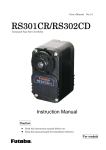
Configuration Flowchart
Enter
Programming
Mode
ENTER
Select Function
Label
Function
Set ASCII Value
Set Decimal Value
Decimal
(100's Value)
Hexdecimal
(High Byte)
Finish ASCII
Code or Decimal
Value Setting
SET
END
Exit With Save
ABORT
Exit Without Save
All DEFAULT
Exit & All Default
READ VERSION
Exit & Read Version
Interface Default
Exit & Interface Default
String Output Flowchart
Preamble
Prefix
Code Name
Code ID
Code Data
Suffix
Postamble
5
Introduction
Decimal
(1's Value)
1
Decimal
(10's Value)
Hexdecimal
(Low Byte)
Default Setting
Code
Read
Length
Truncate
Code
Type
Enable Min. Max. Leading Ending ID
UPC-A
0
0
A
UPC-E
0
0
E
EAN-13
0
0
F
EAN-8
0
0
FF
Code-39
0
0
0
0
M
Interleaved 2 of 5
4
0
0
0
I
Industrial 2 of 5
4
0
0
0
H
Matrix 2 of 5
4
0
0
0
G
Codabar/NW7
0
0
0
0
N
Code-128
0
0
0
0
K
Code-93
0
0
0
0
L
Code-11
0
0
0
0
O
MSI/Plessey
0
0
0
0
P
UK/Plessey
0
0
0
0
R
Telepen
0
0
0
0
S
RSS
0
0
0
0
T
RSS Limit
0
0
0
0
U
RSS Stack
0
0
0
0
V
RSS Expansion Limit
0
0
0
0
W
RSS Expansion Stack
0
0
0
0
X
Adjustment
Beep Loudness
Beep Tone
Beep Duration
Stand-by Time
Led Off Delay
Lamp Off Delay
Good read Time
Double Confirm Times
Tx Gap
Tx Delay
Timeout
Wait Addon Count
Preamble Data
Postamble Data
Prefix Data (All Datas)
Suffix Data (All Datas)
Operation Manual
Value
05
27
10
05
20
05
05
02
00
00
03
10
0016
0016
0016
0D160A16
6
Result
Level 5
2.4 Hz
10 mSec
1 Sec
100 mSec
1000 mSec
100 mSec
Once
1 mSec
10 mSec
1 Sec
Once
<NULL>
<NULL>
<NULL>
<CR><LF>
Manual Label Layout
The scanner must be set by reading the barcode labels in
manual. The discription of label is as follows.
Section
Title
Exit
Program
Function
Title
END
*ZEND*
UPC-A
Truncate Zero
Selection
Label
Disable
*DZA*
Enable
Function
Description
Default
Setting
Specific Adjustments
Truncate Leading / Ending: The
leading or ending digits of barcode
data characters can be truncated
when these values are set to non
zero. It will be read nothing else only
beeps when the truncate value is
more than barcode data digits or the
value of Truncate Leading is overlap
with the Ending. The maximum value
of Truncate digits is 15.
(Range:0010-FF10)
Truncate Ending
*BAP*
Adjustment
(Range:0010-FF10)
(ASCII Code or
Decimal Value)
Insert0 Position
*BAP*
(Range:0010-FF10)
*BAP*
(Range:0010-FF10)
Insert0 data
*AAA*
Code Option
Insert1 Position
Selection
Label
Selection
Description
*BAO*
4
Code ID: A Code ID is a character
Truncate Leading
Chapter
Number
Chapter
Title
(Range:0016-FF16 ASCII Code)
Insert1 data
*AAA*
Range
Description
(Range:0016-FF16 ASCII Code)
ID
*AAA*
(Range:0016-FF16 ASCII Code)
Sub ID
*AAA*
(Range:0016-FF16 ASCII Code)
Page
Number
25
The factory default settings are indicated by bold symbols.
7
Introduction
*DZB*
1
Group
Line
Frequent Question
Q: Why scanner block the keyboard operation?
A: Check the cable connection with your equipment, then turn
power on again.
Q: If the scanner dosen't need an Enter character addition after
each barcode label transmission.
A: Refer to postamble transmission at 66, then set Disable .
Q: If the scanner needs to read single digit code.
A: Refer to Min. code length of code option use "01" in Chapter 4
for single code readable.
Q: If the scanner can’t discriminate an unknown label, but
read manual very well.
A: Refer to code name at 20 to set Enable , read a barcode label,
then you will know what symbology is read. Beside, it maybe
need to verify checksum. Refer to verify checksum of code
option in Chapter 4, and set Enable .
Q: If the scanner transferred characters very slow or lost some
characters when data be output to screen by keyboard
interface
A: You may set caps lock to be Alt+Keypad at 11. Otherwise, it
maybe mis-match of transmission rate, therefore, you can adjust
an appropriate Tx Gap to match your equipment. See 12.
Q: If the scanner only sounds beep when read barcode but
didn’t send data to PC.
A: It is the communication problem between scanner interface and
PC. It may be cuased by cable damaged or wrong interface
setting. Check your cable connection and set the interface
setting again.
Q: What does Tx , Tx Gap mean ?
A: Tx means transmittion. Tx Gap means transmittion of
Inter-character delay. See 12.
Call to the dealer if scanner dose not work properly.
Operation Manual
8
1
Introduction
9
ENTER
*/$%ENT*
Host Interface
Type
0DC1
Keyboard
*0DC1*
0DC2
RS232
If the interface cable you have is PS2
or USB HID, please set as Keyboard.
If it is USB COM or RS232 type,
please set as RS232. .
*0DC2*
Type
ZADE
ALL DEFAULT
*ZADE*
ZDEF
BARCODE
DEFAULT
*ZDEF*
ZKBD
KEYBOARD
DEFAULT
*ZKBD*
Z232 RS232 DEFAULT
*Z232*
ZVER
VERSION
*ZVER*
ZEXT
ABORT
*ZEXT*
ZISP
All Default::All settings will be reset
as bold label,but exclude interface
setting.
Barcode Default:Restore to default
barcode setting
Keyboard
Default:Restore
keyboard interface default setting
to
RS232 Default: Restore to RS232
interface default setting
Version: You can get the firmware
version & date of decoder.
ABORT: To skip or give up current
configuration, so all previous setting
will be aborted before you set END to
finish programming.
ISP
*ZISP*
ISP: After enable ISP, the scanner will
become COM interface and can be
update firmware or configuration to
scanner.
End user please don’t update firmware by yourself, unless you get
correct instruction from your dealer. Because improper procedure may
cuase damage on the scanner.
Operation Manual
10
End
*ZEND*
Keyboard
USB
If select Enable means you use the
usb hid,if select Disable means you
use the ps2 cable.
Disable
1A00
*1A00*
Enable
1A01
Simulation
Disable
1A50
Enable
1A51
*1A50*
*1A51*
Key Pad
The Keypad must be enable if your
application program can accept
numeric code from keypad only. The
scanner will output code as numeric
key-pad did when it read numeric digit.
Disable
1A70
Enable
1A71
*1A70*
*1A71*
Caps Lock
By selecting Caps Lock On or Caps Lock
Off , scanner can get Caps Lock status.
If
Alt+Keypad were selected, Caps
Lock
and
output
will
be
independent.The Auto function can be
effect when USB HID or KB Simulation
is enable.When you set Auto , the
scanner will detect the status of
Keyboard Caps Lock.So the batcode
data outputwill follow the status of
Keyboard Caps Lock.
Auto
*1B80*
Alt+Keypad 1B81
*1B81*
Caps Lock Off 1B82
*1B82*
Caps Lock On 1B83
*1B83*
Example Barcode "ABCdef"
Status
Selection
Caps Lock On
Caps Lock Off
Alt+Keypad
Caps Lock
On
ABCdef
abcDEF
ABCdef
11
1B80
Caps Lock
Off
abcDEF
ABCdef
ABCdef
Interface
It is recommended to Enable the
function if your PC without keyboard
installation. It simulates keyboard
timing and pass keyboard present
status to the PC during power-on.
2
*1A01*
ENTER
*/$%ENT*
Keyboard
Specific Adjustments
Tx Gap
1052
*1052*
(Range:0010-FF10 Unit:1ms)
Tx Delay
1062
*1062*
(Range:0010-FF10 Unit:10ms)
Timeout
1072
*1072*
Tx Gap: It will delay the output timing
of per digit. If the output speed is too
high, the system may not receive all
digits. If so, try out suitable delay time
to make system work properly.
Tx Delay: It can be used while you will
scan several continued short barcode
or multi-filed barcode. This function
will delay the timing after barcode.
(Range:0110-FF10 Unit:1000ms)
It can delay the waiting time of serial
scanner for the handshaking acknowledgment from the host PC.
If scanner didn’t get acknowledgment from host PC after timeout
occur, the scanner will sound 5 beeps as warning. You may need
to check the handhsanking mode or adjust to longer delay timer.
The function is particular useful for some applications which the
host PC will take longer respond time
* TX means : transmission
Example Barcode Data: "ABCD"
Tx Gap: 2ms
Tx Delay: 10ms
1) ENTER Entry Programming
2) Tx Gap 0 2 SET 2ms Inter-char. Delay
︸
02*1ms(Unit)=2ms
10ms Transmit Delay
3) Tx Delay 0 1 SET ︸
01*10ms(Unit)=10ms
4) END
Exit Programming
Output
A
2ms
Operation Manual
B
2ms
C
2ms
12
D
2ms
10ms
End
*ZEND*
Keyboard
Speed
Low
1BD8
*1BD8*
Middle
1BD9
*1BD9*
1BDA
13
Interface
*1BDA*
2
High
ENTER
*/$%ENT*
Keyboard
Layout
1DC0
USA (US)
*1DC0*
1DC1
Here you can set up the scanner’s
language to match your computer
keyboard layout.
UK (UK)
*1DC1*
1DC2
Japan
*1DC2*
1DC3
France(FR)
*1DC3*
1DC4
Germany (GR)
*1DC4*
1DC5
Italian (IT)
*1DC5*
1DC6
Spanish (SP)
*1DC6*
1DC7 Portuguese (PO)
*1DC7*
Operation Manual
14
END
*ZEND*
RS232
USB COM
If the scanner is with USB cable but
virtual COM interface, it should be
programmed as USB COM enable,
otherwise, the data will not be output
to the PC.
Disable
2A00
*2A00*
Enable
2A01
*2A01*
2
Protocol
Clear To Send
Request To Send
Transmit On
Transmit Off
(Hardware Signal)
(Hardware Signal)
(ASCII Code 1316)
(ASCII Code 1116)
None: It only uses TxD and RxD
signal without relation for any
hardware or software handshaking
protocol.
RTS/CTS (CTS/RTS): If the scanner
sent barcode data to host computer, it
will issue the singal of RTS (CTS) first,
and wait for the signal returned from
the host computer. Then it will perform
the normal data communication. If
there is no CTS (RTS) signal returned
from the host computer after timeout
(Response Delay), the scanner will
sound 5 beeps as warning.
None
2CC0
RTS/CTS
2CC1
*2CC0*
*2CC1*
CTS/RTS
2CC2
*2CC2*
Scanner Ready 2CC3
*2CC3*
Data Ready
2CC4
*2CC4*
Xon/Xoff
2CC5
*2CC5*
Scanner Ready: The scanner will issue signal of RTS after
power-on, then transmit data upon receiving active CTS signal.
Data Ready: The scanner will issue signal of RTS to indicate a
successful decoding and will transmit data upon receiving CTS
signals.
Xon/Xoff: When the host PC can’t accept data, it will notice the
scanner to suspend data transmission by sending an Xoff code,
and Xon as to be continuded.
Remark : If the interface is USB COM, it does not support
Protocol setting.
15
Interface
CTS:
RTS:
Xon:
Xoff:
ENTER
*/$%ENT*
RS232
Baud Rate
2BDC
115200 Bps
*2BDC*
2BDB
57600 Bps
*2BDB*
2BDA
38400 Bps
*2BDA*
2BD9
19200 Bps
*2BD9*
2BD8
9600 Bps
*2BD8*
2BD7
4800 Bps
*2BD7*
2BD6
2400 Bps
*2BD6*
2BD5
1200 Bps
*2BD5*
2BD4
600 Bps
*2BD4*
2BD3
300 Bps
*2BD3*
Data Bits
2A60
7 Bits
*2A60*
2A61
8 Bits
*2A61*
Stop Bits
2A70
1 Bits
*2A70*
2A71
2 Bits
*2A71*
Operation Manual
16
END
*ZEND*
RS232
Parity
None
2CD0
Odd
2CD1
*2CD0*
*2CD1*
2CD2
Mark
2CD3
*2CD3*
Space
2CD4
*2CD4*
CTS Trigger
Disable
2A50
Enable
2A51
*2A50*
*2A51*
17
Interface
*2CD2*
2
Even
ENTER
*/$%ENT*
RS232
Specific Adjustments
2052
Tx Gap
*BAL*
Tx Gap: It will delay the outout timing
of per digit . It is same as Tx Gap of
keyboard wedge on 12.
(Range:0010-FF10 Unit:1ms)
2062 Tx Delay
*BAM*
Tx Delay: It is a delay time after
barcode. It is same as Tx Delay of
Keyboard wedge on 12.
(Range:0010-FF10 Unit:10ms)
2072
Timeout
*BAN*
Timeout: It is same as Timeout of
Keyboard wedge on 12.
(Range:0110-FF10 Unit:1000ms)
Operation Manual
18
END
System Control
*ZEND*
Power on Music
The power-on music will indicate the
scanner as successful power on. It
can be inhibitted by setting Disable .
Disable
0A40
*0A40*
Enable
0A41
*0A41*
Power on Trigger
The scanner can be activated LED
light source without trigger pushed
by setting Enable ,
Disable
0A50
Enable
0A51
*0A50*
Disable
8B00
*8B00*
Enable
8B01
*8B01*
Good read Vibrator
If set Enable ,the Scanner Vibrates
when successfully read a barcode.
This function is only applicable in CM
200 series. For CM 500 series,
vibration motor is an extra purchase
option.
Disable
8B20
Enable
8B21
*8B20*
*8B21*
Reject Same
If set Enable,the same barcode will not
be scanned. But this function only work
under Continue Mode.
Disable
8B60
Enable
8B61
*8B60*
*8B61*
Object Detect
This is auto sensor function. So even
the LED is off, but when object or
barcode under the scan range, it will be
auto LED on and scan barcode by set
Enable.This function is only applicable
in CM003, CM008, CM300 and CM
1002 series.
19
Disable
0A60
Enable
0A61
*0A60*
*0A61*
System Control
Good read Beep
The scanner will sound a beep for per
successful barcode reading when it is
set Enable . And the beep Volume ,
Tone and Time can be adjusted by
setting on 23.
3
*0A51*
ENTER
*/$%ENT*
System Control
Tx Length
8C50
Disable
*8C50*
8C51
If your application need Barcode
Length, you must set this function to
be Enable .
Enable
*8C51*
Force Case
8E80
None
*8E80*
8E81
Inverse
*8E81*
8E82
Lowercase
*8E82*
8E83
It will converse all output digits to
be same printing-case, even one
barcode may have two kinds of
case.
Example Barcode "BarCode",
Uppercase
Lowercase
BARCODE
barcode
Uppercase
*8E83*
Double Confirm
8B70
Disable
*8B70*
8B71
Enable
*8B71*
When barcode is easy misreading, try
this function. Then scanner will output
the data after same decoding by
double times. For more times confirm,
please refer Doubble Confirm Count on
24. But double confirm will delay
the scan speed.
Tx Code ID
8C30
Disable
*8C30*
8C31
If your application need Code ID, you
must set this function to be Enable .
Enable
*8C31*
Code ID Position
8C20
Before Code
Data
*8C20*
Upon your usage, the output position
of Code ID can be Before or After Code
Data by setting.
8C21 After Code Data
*8C21*
Operation Manual
20
END
System Control
*ZEND*
Tx Control Code
If you want the control code to be
output, then set it as Enable.
Disable
8C40
Enable
8C41
*8C40*
*8C41*
Tx Code Name
8C00
Enable
8C01
*8C00*
*8C01*
Return Detect
System Control
This Function is only applicable in
CM301, CM-302 and CM901 with
special designed Barcode Scanner
Holder.
Disable
3
This function can show unknown
barcode type which is readable by
this scanner. When Enable is set,
Code Name will be showed on front
of per barcode, then you will know
what kind of barcode symbology it is.
Disable
0B80
Enable
0B81
*0B80*
*0B81*
Enable: When placing the barcode
scanner on the holder, enable this
With Auto Trigger 0B82
function will turn off the LED beam
light in any scanning mode, if the
scanner has been preset the
scanning mode as”auto detect”. Auto detect function stays the
same.
*0B82*
With auto Trigger: When “With Auto trigger” is activated, the
scanner LED beam light will automatically turn on when taking off
the scanner from the holder. The scanning mode can be implement
with this function except “Momentary” mode.
Note: This function is only applicable in CM301, CM 302 and
CM901 model with special designed barcode scanner holder.
and these are optional extra purchase function and items.
21
ENTER
*/$%ENT*
System Control
Scanning Mode
8AC2
Good read Off
*8AC2*
8AC4
Momentary
*8AC4*
8AC5
Alternate
*8AC5*
8AC3
Timeout Off
*8AC3*
8AC6
Timeout Flash
*8AC6*
8AC1
Continue
*8AC1*
8AC0
Test
*8AC0*
Good read Off: The LED light source
will be on when the tirgger is pushed
and then be off when a barcode is
read successfully. And you can refer
Stand-by Time on 23.
Momentary: The trigger will act as
a switch. When the trigger is pressed,
it will scan barcode, when it is
released it will stop to scan.
Alternate: The trigger will be act
as a toggle switch. Press button to
active or stop scanning.
Timeout Off: The scanner will scan
barcode when trigger is pressed,
and it will stop scanning when barcode
is not decoded after stand-by
time elapsed. Stand-by Time setting is
on 23.
TimeOut Flash: The scanner will scan barcode when trigger is
pressed, Light source turns flashing when barcode is not decoded
after stand-by time elapsed. Stand-by Time setting is on 23. This
function is only applicable in CM-003 series.
Continue: No need to press the trigger then the scanner can read
barcode when the LED light source is on.
Test: The scanner will always keep reading continuously and same
barcode reading is allowed without double confirm. The feature can
test the performance of scan speed and sensitive.
For saving power and keeping longer life of laser component,
the laser beam and motor will be stopped when no code is decoded
for all above scanning mode .
Operation Manual
22
END
System Control
*ZEND*
Specific Adjustments
Beep Adjustments: You can adjust
Beep Volume , Beep Tone and
Beep Time of good reading upon your
pavorite usage.
8142
*8142*
(Range:0010-1010 Unit:Level)
Beep Tone
8162
*8162*
(Range:0010-5010 Unit:100Hz)
Beep Time
8152
*8152*
(Range:0010-FF10 Unit:10ms)
Standby Time
8122
*8122*
Object Detec Level : It is the
function of auto detection. You can
set up the level of detection
sensitivity you want.
Object Detect Time : It can adjust
the time for auto detection duration.
LED Off Delay
8192
*8192*
(Range:0010-FF10 Unit:10ms)
Lamp off Delay
8172
*8172*
(Range:0010-FF10 Unit:1s)
Good read Time
8112
*8112*
(Range:0010-FF10 Unit:100ms)
Object Detect level 0052
*0052*
(Range:0010-FF10)
Object Detect Time 0062
*0062*
(Range:0010-FF10 Unit:100ms)
0072
Setup Timeout
Setup Timeout : It is the timer
between scanner go into “ Enter” and
(Range:0010-FF10 Unit:1000ms)
quit “ End”. So that means you need
to finish whole setting before the setup timeout timing. Otherwise,
the scanner will quit the setting mode as soon as the time is up.
*0072*
23
System Control
(Range:0010-FF10 Unit:1s)
LED/Lamp Off Delay: There are two
kinds LED light source durations for
all scanning mode. The scanner light
source will be flash when no code is
read until Standby Time is timeout. The
Led Off Delay is lighting duration and
the Lamp Off Delay is blanking
duration. The scanner can still read
barcode during the light source is
flashing and then be waked up
automatically when read a barcode.
3
Stand-by Time: The
timeout
duration can be adjusted from 1 to 99
seconds. The Stand-by Time is only
effective during Good-read Off &
Timeout Off mode for CCD scanner.
If no code to be read after Stand-by
Time , on laser scanner,the laser
beam and motor will be shutdown to
keep the life time of laser diode.
Beep Volume
ENTER
*/$%ENT*
System Control
Specific Adjustments
81A2
Vibrator Off Delay
*81A2*
(Range:0010-FF10 Unit:10ms)
8132
Wait Addon Count
*8132*
(Range:0010-FF10)
8102 Double Confirm
count
*8102*
(Range:0010-FF10)
81E2 Global Min. Length
*81E2*
(Range:0010-FF10)
81F2 Global Max. Length
*81F2*
(Range:0010-FF10)
ZCLK Set Date & Time
*ZCLK*
Vibrator Off Delay: Sets the duration
of vibration of scanner, Unit: 10 ms.
Wait Addon Count: This setting is
used for WPC add-on code, such as
EAN and UPC. The WPC code must
be decoded first, then Add-on. Add-on
may not be decoded with WPC at the
same time. Therefore, you can set
wait addon count to force the add-on
code must be output with WPC code
together.
If the Wait addon count is set as
“0”,the barcode data will only be output
with add-on code.
Double Confirm Count: The more
confirm times the less miss-reading
will be happened. This feature should
depend on the symbology and printing
quality of barcodes. Selecting a higher
value will reduce read-out speed.
Global Min. / Max. Length: When you
set min. length, barcode digits number which is under the min.
length, it will not be decoded. If you set Max. length, the barcode
digits which is over the value will not be decoded,neither. But the
values setting will not effect in some fixed length symbobolgies (i.e.
UPC and EAN is called WPC).
If Min. Length and Max Length are specified, and Min.length > Max.
Length, the barcode data will only decoded by the length of two
specified value of Min. Length and Max. Length.
Set Date & Time: Date and Time setting. The setting format will be
(yy/mm/dd/hh/mm/). For the example, setting the scanner date and
time as 2012,Aug,30.13:30. (Note: this function is only
applicable in CM200 and CM500 series).
Procedure:
1) Scan “Enter” barcode
2) Scan “Set Date & time” barcode
3) Refer to ASCII table in page 82, and scan 1208301330.as
(2012,Aug,30,13:30)
4) Scan “SET” barcode
5) Scan “End” barcode
Operation Manual
24
END
System Control
*ZEND*
3
System Control
25
ENTER
*/$%ENT*
UPC-A
Read
AA70
Disable
Format
*AA70*
AA71
Leading Data Digts Check
Zero (11 Digits) Digit
Enable
*AA71*
Addon Type
AB90
None
*AB90*
AB91
Addon 2
*AB91*
AB92
Addon 5
*AB92*
AB93
The
Add-on
barcode
is
the
supplemental 2 or 5 digits for WPC
code.
Format
Leading Data Digits Check Add-on
Zero (11 Digits) Digit 2 or 5
Addon 2+5
*AB93*
Wait Addon
AA00
Disable
*AA00*
AA01
Enable
*AA01*
It is recommended to set Enable if
you want the UPC can be output with
add-on code together. Please enable
this function first and refer Wait Addon
Count at 24 for good reading of
Add-on code.
Tx Chksum
AA60
Disable
*AA60*
AA61
By setting Enable , check characters
will be transmitted.
Enable
*AA61*
Operation Manual
26
END
*ZEND*
UPC-A
Truncate Zero
The all leading "0" of barcode data will
be truncated when this function is
enabled.
Example Barcode "00054321"
*AA50*
Output "54321"
*AA51*
Disable
AA50
Enable
AA51
Specific Adjustments
Truncate Lead / End: The leading or
ending character of barcode data will
be truncated when these values are
set to non zero. It will be output
nothing except beeps if the truncate
value is more than barcode data digits
or
overlap with the Ending. The
maximum value of Truncate digits is
15.
*A082*
(Range:0010-FF10)
Truncate End
A092
*A092*
(Range:0010-FF0)
Insert0 Position A0C2
*A0C2*
(Range:0010-FF10)
Insert1 Position A0D2
*A0D2*
(Range:0010-FF10)
Insert0 Data
A0EB
*A0EB*
(Range:0016-FF16 ASCII Code)
Insert1 Data
A10B
*A10B*
(Range:0016-FF16 ASCII Code)
ID
A12B
*A12B*
(Range:0016-FF16 ASCII Code)
Sub ID
A14B
*A14B*
(Range:0016-FF16 ASCII Code)
If the insert position you set is 0, the character will be inserted in
the front of the barcode. If the value is FF, the inserted position
will be behind the barcode. If the value is 1, the character will be
inserted behind the first barcode digit. If the value is 2, the
character will be inserted behind the second digit……and so forth.
27
Code Option
Insert Position & Data : This function
can append one or two characters into
the barcode data. But you need to
make sure the value of insert position
can not be greater than the length of
barcode. Otherwise, your setting will
be no effect. You can add an Insert
Data 0 at Insert Position 0
A082
4
ID: The ID is a character which is
used to represent the symbobly while
successful reading. It will be prefixed
on the front or back barcode. There
are some symbobolgies (i.e. UPC-E
and EAN-8) include 2 Code ID. If your
application need Code ID, please
enable Code ID Transmission first.
You can refer the setting at 20.
Truncate Lead
ENTER
*/$%ENT*
UPC-E
Read
BA70
Disable
Format
*BA70*
BA70
Leading Data Digits Check
Zero (6 Digits) Digit
Enable
*BA71*
Add-on
BB90
None
*BB90*
BB91
Addon 2
Format
Leading Data Digits Check Add-on
Zero (6 Digits) Digit 2 or 5
*BB91*
BB92
Addon 5
*BB92*
BB93
Addon 2+5
*BB93*
Wait Addon
BA00
Disable
Refer 26.
*BA00*
BA01
Enable
*BA01*
Expansion
BA10
Disable
*BA10*
BA11
Enable
*BA11*
This expansion function is for UPC-E
and EAN-8 only. It will extend the
barcode to be 13-digits by “ 0 “ zero. .
Example Barcode "01236547"
Output "0012360000057"
Tx CheckSum
BA60
Disable
Refer 26.
*BA60*
BA61
Enable
*BA61*
Operation Manual
28
END
*ZEND*
UPC-E
Truncate Zero
Refer 27.
Disable
BA50
Enable
BA51
*BA50*
*BA51*
Truncate Zero
Refer 27.
Truncate Lead
B082
*B082*
(Range:0010-FF10)
Truncate End
B092
*B092*
(Range:0010-FF10)
(Range:0010-FF10)
Insert1 Position B0D2
*B0D2*
(Range:0010-FF10)
Insert0 Data B0EB
*B0EB*
(Range:0016-FF16 ASCII Code)
Insert1 Data B10B
*B10B*
(Range:0016-FF16 ASCII Code)
ID
B12B
*B12B*
(Range:0016-FF16 ASCII Code)
Sub ID
B14B
*B14B*
(Range:0016-FF16 ASCII Code)
29
Code Option
*B0C2*
4
Insert0 Position B0C2
ENTER
*/$%ENT*
EAN-13
Read
CA70
Disable
Format
*CA70*
CA71
Data Digts Check
(12 Digits) Digit
Enable
*CA71*
Addon type
CB90
None
Format
*CB90*
CB91
Data Digits Check Add-on
(12 Digits) Digit 2 or 5
Addon 2
*CB91*
CB92
Addon 5
*CB92*
CB93
Addon 2+5
*CB93*
Wait Addon
CA00
Disable
Refer 26.
*CA00*
Enable
CA01
*CA01*
ISBN/ISSN Conversion
CA10
Disable
*CA10*
CA11
Enable
*CA11*
The ISBN ( International Standard
Book
Number
)
and
ISSN
(International Standard Serial Number)
are especial barcode for book and
magazine. The ISBN is 10 digits with
leading "978" and the ISSN is 8 digits
with leading "977" of "EAN-13" .
Example Barcode "9789572222720"
Output "9572222724"
Example Barcode "9771019248004"
Output "10192484"
Operation Manual
30
END
*ZEND*
EAN-13
Tx Chksum
Refer 26.
Disable
CA60
*CA60*
Enable
CA610
*CA61*
Truncate Zero
Refer 27.
Disable
CA50
Enable
CA51
*CA50*
*CA51*
Specific Adjustments
Refer 27.
Truncate Lead
C082
4
*C082*
(Range:0010-FF10)
C092
*C092*
(Range:0010- FF)
Insert0 Position C0C2
*C0C2*
(Range:0010- FF)
Insert1 Position C0D2
*C0D2*
(Range:0010- FF)
Insert0 Data
C0EB
*C0EB*
(Range:0016-FF16 ASCII Code)
Insert1 Data
C10B
*C10B*
(Range:0016-FF16 ASCII Code)
ID
C12B
*C12B*
(Range:0016-FF16 ASCII Code)
Sub ID
C14B
*C14B*
(Range:0016-FF16 ASCII Code)
31
Code Option
Truncate End
ENTER
*/$%ENT*
EAN-8
Read
DA70
Disable
Format
*DA70*
DA71
Data Digits Check
(7 Digits) Digit
Enable
*DA71*
Addon Type
DB90
None
Format
*DB90*
DB91
Data Digits Check Add-on
(7 Digits) Digit 2 or 5
Addon 2
*DB91*
DB92
Addon 5
*DB92*
DB93
Addon 2+ 5
*DB93*
Wait Addon
DA00
Disable
Refer 26.
*DA00*
DA01
Enable
*DA01*
Expansion
DA10
Disable
Refer 26.
*DA10*
DA11
Enable
*DA11*
Truncate Zero
DA50
Disable
Refer 27.
*DA50*
DA51
Enable
*DA51*
Operation Manual
32
END
*ZEND*
EAN-8
Tx Chksum
Refer 26.
Disable
DA60
*DA60*
Enable
DA61
*DA61*
Specific Adjustments
Refer 27.
Truncate Lead
D082
*D082*
(Range:0010-FF)
Truncate End
D092
*D092*
(Range:0010- FF)
Insert0 Position D0C2
4
*D0C2*
(Range:0010- FF)
*D0D2*
(Range:0010- FF)
Insert0 Data
D0EB
*D0EB*
(Range:0016-FF16 ASCII Code)
Insert1 Data
D10B
*D10B*
(Range:0016-FF16 ASCII Code)
ID
D12B
*D12B*
(Range:0016-FF16 ASCII Code)
Sub ID
D14B
*D14B*
(Range:0016-FF16 ASCII Code)
33
Code Option
Insert1 Position D0D2
ENTER
*/$%ENT*
CODE-39
Read
EA70
Disable
*EA70*
EA71
Enable
Format
Start Data Digits Checksum End
"*" (Variable) (Optional) "*"
*EA71*
Type
EB90
Standard
*EB90*
EB91
Full ASCII
*EB91*
The Full ASCII function is an enhanced
setting for Code-39 which is with
toatal 128 digits to represent Full ASCII
code. It must be combined by either
one of + , % , $ or / and one of
alpha character (A to Z).
Format
EBA0
None
*EBA0*
EBA1
Code-32
*EBA1*
EBA2
The Code-32 symbology (Italian
Pharmaceutical) is another version of
Code-39 which max. can be 10 digits
and can be 0 – 9 digits. The leading A
is an optional character and can be
set to be transmitted or not.
Code-32 with ‘A’
*EBA2*
Tx Start/End
EA20
Disable
*EA20*
EA21
Enable
The Start and End character of
Code-39 must be
"". You can
transmit all data digits including two
"" by set Enable.
*EA21*
Truncate Zero
EA50
Disable
Refer 27.
*EA50*
EA51
Enable
*EA51*
Operation Manual
34
END
*ZEND*
CODE-39
Verify Checksum
The checksum of Code-39 is optional
and it is made the sum module 43 as the
numerical value of the data digits.
Disable
EBB0
Enable
EBB1
*EBB0*
*EBB1*
Tx Checksum
By setting Enable , checksum will be
transmitted.
Disable
EA60
Enable
EA61
*EA60*
*EA61*
Truncate Lead
E082
(Range:0010-FF)
Truncate End
E092
*E092*
(Range:0010- FF)
Min. Length
E0A
*E0A2*
(Range:0110- FF)
Max. Length
E0B2
*E0B2*
(Range:0110- FF)
Insert0 Position E0C2
*E0C2*
Refer 27.
(Range:0110- FF)
Insert1 Position E0D2
*E0D2*
(Range:0110- FF)
35
Code Option
*E082*
4
Specific Adjustments
Min. / Max. Code Length: Each
symbology has its own Min./Max. Code
Length. They can be set to qualify data
entry. If the Min./Max. Code Length is
zero, the Public Min./Max. Code Length
will be changed. The length is defined by
the actual barcode length transmitted. If
the barcode length is over the value of
min/max. length, it will not be output.
Make sure the Minimum length value is
not bigger than the Maximum length,
otherwise, this barcode will not be output.
In particular, you can set the same value
for Minimum and Maximum length to
have the fixed length barcode must be
decoded.
ENTER
*/$%ENT*
CODE-39
Specific Adjustments
E0DB
Insert0 Data
Refer 27.
*E0EB*
(Range:0016-FF16 ASCII Code)
E10B
Insert1 Data
*E10B*
(Range:0016-FF16 ASCII Code)
E12B
Code ID
*E12B*
(Range:0016-FF16 ASCII Code)
E14B
Code-32 ID
*E14B*
(Range:0016-FF16 ASCII Code)
Operation Manual
36
END
Interleaved 2 of 5
*ZEND*
Read
Format
Disable
HA70
Enable
HA71
*HA70*
Data Digits Checksum
(Variable) (Optional)
*HA71*
Verify Checksum
The checksum is made the sum
module 10 as the numberical values
of all data digits.
Disable
HBB0
Enable
HBB1
*HBB0*
*HBB1*
Tx Checksum
Refer 26.
Enable
HA61
*HA60*
*HA61*
Truncate Zero
Refer 27.
Disable
HA50
Enable
HA51
*HA50*
*HA51*
37
Code Option
HA60
4
Disable
ENTER
*/$%ENT*
Interleaved 2 of 5
Specific Adjustments
H082
Truncate Lead
*H082*
(Range:0010-FF)
H092
Truncate End
*H092*
(Range:0010- FF)
H0A2
Min. Length
*H0A2*
(Range:0010- FF)
H0B2
Because, the start and end of
interleaved 2 of 5 code is not olny
one patten in symbol. In order to
prevent partial reading, it is
recommand to use the fixed code
length for each 2 of 5 code barcode
label. Setting the same Min./Max.
Code Length , it is like a length filter,
and only one length is accepted.
Refer 27 & 35.
Max. Length
*H0B2*
(Range:0010- FF)
H0C2
Insert0 Position
*H0C2*
(Range:0010- FF)
H0D2 Insert1 Positionh
*H0D2*
(Range:0010- FF)
H0EB Insert0 Data
*H0EB*
(Range:0016-FF16 ASCII Code)
H10B Insert1 Data
*H10B*
(Range:0016-FF16 ASCII Code)
H12B
ID
*H12B*
(Range:0016-FF16 ASCII Code)
H14B
Sub ID
*H14B*
(Range:0016-FF16 ASCII Code)
Operation Manual
38
END
Industrial 2 of 5
*ZEND*
Read
Format
Disable
IA70
Enable
IA71
*IA70*
Data Digits Checksum
(Variable) (Optional)
*IA71*
Truncate Zero
Refer 27.
Disable
IA50
Enable
IA51
*IA50*
*IA51*
Tx Checksum
Refer 26.
Enable
IA61
*IA60*
*IA61*
Verify Checksum
The checksum is made the sum
module 10 as the numberical values
of all data digits.
Disable
IBB0
Enable
IBB1
*IBB0*
*IBB1*
39
Code Option
IA60
4
Disable
ENTER
*/$%ENT*
Industrial 2 of 5
Specific Adjustments
I082
Truncate Lead
Refer 27, 35.
*I082*
(Range:0010-FF)
I092
Truncate End
*I092*
(Range:0010- FF)
I0A
Min. Length
*I0A2*
(Range:0010- FF)
I0B2
Max. Length
*I0B2*
(Range:0010- FF)
I0C2
Insert0 Position
*I0C2*
(Range:0010- FF)
I0D2 Insert1 Positionh
*I0D2*
(Range:0010- FF)
I0EB Insert0 Data
*I0EB*
(Range:0016-FF16 ASCII Code)
I10B Insert1 Data
*I10B*
(Range:0016-FF16 ASCII Code)
I12B
ID
*I12B*
(Range:0016-FF16 ASCII Code)
I14B
Sub ID
*I14B*
(Range:0016-FF16 ASCII Code)
Operation Manual
40
END
*ZEND*
Matrix 2 of 5
Read
Format
Disable
JA70
Enable
JA71
*JA70*
Data Digits Checksum
(Variable) (Optional)
*JA71*
Truncate Zero
Refer 27.
Disable
JA50
Enable
JA51
*JA50*
*JA51*
Tx Checksum
JA60
Enable
JA61
*JA60*
*JA61*
Verify Checksum
The checksum is made the sum
module 10 as the numberical values
of all data digits.
Disable
JBB0
Enable
JBB1
*JBB0*
*JBB1*
41
Code Option
Disable
4
Refer 26.
ENTER
*/$%ENT*
Matrix 2 of 5
Specific Adjustments
J082
Truncate Lead
Refer 27 35.
*J082*
(Range:0010-FF10)
J092
Truncate End
*J092*
(Range:0010-FF10)
J0A2
Min. Length
*J0A2*
(Range:0010-FF10)
J0B2
Max. Length
*J0B2*
(Range:0010-FF10)
J0C2
Insert0 Position
*J0C2*
(Range:0010-FF10)
J0D2
Insert1 Positionh
*J0D2*
(Range:0010-FF10)
J0EB
Insert0 Data
*J0EB*
(Range:0016-FF16 ASCII Code)
J10B
Insert1 Data
*J10B*
(Range:0016-FF16 ASCII Code)
J12B
ID
*J12B*
(Range:0016-FF16 ASCII Code)
J14B
Sub ID
*J14B*
(Range:0016-FF16 ASCII Code)
Operation Manual
42
END
*ZEND*
Codabar/NW7
Read
Format
Disable
Start Data Digits Cheksum End
(Variable) (Optional)
GA70
*GA70*
Enable
GA71
*GA71*
Type
The Codabar has four kinds of
Start/End patten, you may choice
one to match your application.
ABCD/ABCD
GB90
abcd/abcd
GB91
*GB90*
*GB91*
ABCD/TN*E
GB92
*GB92*
abcd/tn*e
*GB93*
4
Same Start/End Pair
Code Option
Sometimes, the Codabar requires
only same Start/End patten can be
decoded.
GB93
Disable
GA00
Enable
GA01
*GA00*
*GA01*
Tx Start/End
You can transmit all data digits
including Start/End by set Enable.
Disable
GA20
Enable
GA21
*GA20*
*GA21*
Verify Checksum
The checksum is made as the sum
module 16 of the numberical values
of all data digits.
Disable
GBB0
Enable
GBB1
*GBB0*
*GBB1*
43
ENTER
*/$%ENT*
Codabar/NW7
Tx Checksum
GA60
Disable
Refer 26.
*GA60*
GA61
Enable
*GA61*
Truncate Zero
GA50
Disable
Refer 27.
*GA50*
GA51
Enable
*GA51*
Operation Manual
44
END
*ZEND*
Codabar/NW7
Specific Adjustments
Refer 27, 35.
Truncate Lead
G082
*G082*
(Range:0010-FF10)
Truncate End
G092
*G092*
(Range:0010-FF10)
Min. Length
G0A2
*G0A2*
(Range:0010-FF10)
Max. Length
G0B2
*G0B2*
(Range:0010-FF10)
Insert0 Position
G0C2
*G0C2*
(Range:0010-FF10)
Insert0 Data G0EB
*G0EB*
(Range:0016-FF16 ASCII Code
Insert1 Data G10B
*G10B*
(Range:0016-FF16 ASCII Code
ID
G12B
*G12B*
(Range:0016-FF16 ASCII Code)
Sub ID G14B
*G14B*
(Range:0016-FF16 ASCII Code)
45
Code Option
*G0D2*
4
(Range:0010-FF10)
Insert1 Positionh G0D2
ENTER
*/$%ENT*
Code-128
Read
FA70
Disable
Format
*FA70*
FA71
Data Digits Checksum
(Variable) (Optional)
Enable
*FA71*
Type
FB90
Standard
*FB90*
FB91
UCC-128
*FB91*
The Code-128 can be translated to
UCC-128 format if it starts with FNC1
character. The first FNC1 will be
translated to "]C1", and next to be a
concatenation code as <GS>(7F16).
]C1 Datas <GS> Datas Checksum
Verify Checksum
FBB0
Disable
*FBB0*
FBB1
The checksum is presented as the
sum module 103 of all data digits.
Enable
*FBB1*
Tx Checksum
FA60
Disable
Refer 26.
*FA60*
FA61
Enable
*FA61*
Truncate Zero
FA50
Disable
Refer 27.
*FA50*
FA51
Enable
*FA51*
Operation Manual
46
END
*ZEND*
Code-128
Specific Adjustments
Refer 27, 35.
Truncate Lead
F082
*F082*
(Range:0010-FF10)
Truncate End
F092
*F092*
(Range:0010-FF10)
Min. Length
F0A2
*F0A2*
(Range:0010-FF10)
Max. Length
F0B2
*F0B2*
(Range:0010-FF10)
F0C2
(Range:0010-FF10)
Insert1 Positionh F0D2
*F0D2*
(Range:0010-FF10)
Insert0 Data
F0EB
*F0EB*
(Range:0016-FF16 ASCII Code)
Insert1 Data
F10B
*F10B*
(Range:0016-FF16 ASCII Code)
ID
F12B
*F12B*
(Range:0016-FF16 ASCII Code)
Sub ID
F14B
*F14B*
(Range:0016-FF16 ASCII Code)
47
Code Option
*F0C2*
4
Insert0 Position
ENTER
*/$%ENT*
Code-93
Read
KA70
Disable
*KA70*
KA71
Enable
Format
Data Digits Checksum1 Checksum2
(Variable) (Optional) (Optional)
*KA71*
Verify Checksum
KBB0
Disable
*KBB0*
KBB1
The checksum is presented as the
sum module 47 of all data digits.
One
*KBB1*
KBB2
Two
*KBB2*
Tx Checksum
KA60
Disable
Refer 26.
*KA60*
KA61
Enable
*KA61*
Truncate Zero
KA50
Disable
Refer 27.
*KA50*
KA51
Enable
*KA51*
Operation Manual
48
END
*ZEND*
Code-93
Specific Adjustments
Refer 27, 35.
Truncate Lead
K082
*K082*
(Range:0010-FF10)
Truncate End
K920
*K092*
(Range:0010-FF10)
Min. Length
K0A2
*K0A2*
(Range:0010-FF10)
Max. Length
K0B2
(Range:0010-FF10)
Insert0 Position
K0C2
(Range:0010-FF10)
Insert1 Positionh K0D2
*K0D2*
(Range:0010-FF10)
K0EB
*K10B*
(Range:0016-FF16 ASCII Code
Insert1 Data
K10B
*K0EB*
(Range:0016-FF16 ASCII Code
ID
K12B
*K10B*
(Range:0016-FF16 ASCII Code)
Sub ID K14B
*K14B*
(Range:0016-FF16 ASCII Code)
49
Code Option
*K0C2*
Insert0 Data
4
*K0B2*
ENTER
*/$%ENT*
Code-11
Read
Disable
LA70
*LA70*
Enable
LA71
Format
Data Digits Checksum1 Checksum2
(Variable) (Optional) (Optional)
*LA71*
Verify Checksum
LBB0
Disable
*LBB0*
LBB1
The checksum is presented as the
sum module 11 of all data digits.
One
*LBB1*
LBB2
Two
*LBB2*
Tx Checksum
LA60
Disable
*LA60*
LA61
Enable
By setting Enable , checksum1 and
checksum2 will be transmitted by the
way you set on the checksum
verificvation.
*LA61*
Truncate Zero
LA50
Disable
Refer 27.
*LA50*
LA51
Enable
*LA51*
Operation Manual
50
END
*ZEND*
Code-11
Specific Adjustments
Refer 27, 35.
Truncate Lead
L082
*L082*
(Range:0010-FF10)
Truncate End
L920
*L092*
(Range:0010-FF10)
Min. Length
L0A2
*L0A2*
(Range:0010-FF10)
Max. Length
L0B2
*L0B2*
(Range:0010-FF10)
*L0C2*
(Range:0010-FF10)
Code Option
L0C2
4
Insert0 Position
Insert1 Positionh L0D2
*L0D2*
(Range:0010-FF10)
Insert0 Data
L0EB
*L0EB*
(Range:0016-FF16 ASCII Code)
Insert1 Data
L10B
*L10B*
(Range:0016-FF16 ASCII Code)
ID
L12B
*L12B*
(Range:0016-FF16 ASCII Code)
Sub ID L14B
*L14B*
(Range:0016-FF16 ASCII Code)
51
ENTER
*/$%ENT*
MSI/Plessey
Read
Disable
MA70
*MA70*
Enable
MA71
Format
Data Digits Checksum1 Checksum2
(Variable) (Optional) (Optional)
*MA71*
Verify Checksum
MBB0
Disable
*MBB0*
MBB1
Mod 10
*MBB1*
MBB2
Mod 10/10
*MBB2*
MBB3
The MSI/Plessey has one or two
optional checksum characters. The
checksum is presented by 3 kinds of
method as
Mod 10 ,
Mod 10/10
and Mod 11/10 . The checksum1 and
checksum2 will be calculated as the
sum module 10 or 11 of the data
digits.
Mod 11/10
*MBB3*
Tx Checksum
MA60
Disable
Refer 26.
*MA60*
MA61
Enable
*MA61*
Truncate Zero
MA50
Disable
Refer 27.
*MA50*
MA51
Enable
*MA51*
Operation Manual
52
END
*ZEND*
MSI/Plessey
Specific Adjustments
Refer 27, 35.
Truncate Lead
M082
*M082*
(Range:0010-FF10)
Truncate End
M092
*M092*
(Range:0010-FF10)
Min. Length
M0A2
*M0A2*
(Range:0010-FF10)
Max. Length
M0B2
*M0B2*
(Range:0010-FF10)
M0C2
*M0C2*
*M0D2*
(Range:0010-FF10)
Insert0 Data
M0EB
*M0EB*
(Range:0016-FF16 ASCII Code)
Insert1 Data
M10B
*M10B*
(Range:0016-FF16 ASCII Code)
ID
M12B
*M12B*
(Range:0016-FF16 ASCII Code)
Sub ID M14B
*M14B*
(Range:0016-FF16 ASCII Code)
53
Code Option
(Range:0010-FF10)
Insert1 Positionh M0D2
4
Insert0 Position
ENTER
*/$%ENT*
UK/Plessey
Read
NA70
Disable
Format
*NA70*
NA71
Data Digits Checksum1+2
(Variable)
(Optional)
Enable
*NA71*
Checksum
Verify Checksum
Verification
NBB0
Disable
Refer 26.
*NBB0*
NBB1
Enable
*NBB1*
Tx Checksum
NA60
Disable
Refer 26.
*NA60*
NA61
Enable
*NA61*
Truncate Zero
NA50
Disable
Refer 27.
*NA50*
NA51
Enable
*NA51*
Operation Manual
54
END
*ZEND*
UK/Plessey
Specific Adjustments
Refer 27, 35.
Truncate Lead
N082
*N082*
(Range:0010-FF10)
Truncate End
N092
*N092*
(Range:0010-FF10)
Min. Length
N0A2
*N0A2*
(Range:0010-FF10)
Max. Length
N0B2
*N0B2*
(Range:0010-FF10)
*N0C2*
(Range:0010-FF10)
Code Option
N0C2
4
Insert0 Position
Insert1 Position
N0D2
*N0D2*
(Range:0010-FF10)
Insert0 Data
N0EB
*N0EB*
(Range:0016-FF16 ASCII Code)
Insert1 Data
N10B
*N10B*
(Range:0016-FF16 ASCII Code)
ID
N12B
*N12B*
(Range:0016-FF16 ASCII Code)
Sub ID N14B
*N14B*
(Range:0016-FF16 ASCII Code)
55
ENTER
*/$%ENT*
Telepen
Read
OA70
Disable
Format
*OA70*
OA71
Data Digits Checksum
(Variable) (Optional)
Enable
*OA71*
Type
OB90
Numeric
*OB90*
OB91
ASCII
*OB91*
OB92
Auto Switching
A Telepen can be transimtted by
Numeric and ASCII format. Characters
can be mixed the both format into the
Telepen barcode. By setting Auto
Switching , datas can be conversed
between Numeric and Full ASCII by
character <DLE>(7F16) automatically.
*OB92*
Verify Checksum
OBB0
Disable
Refer 26.
*OBB0*
OBB1
Enable
*OBB1*
Tx Checksum
OA60
Disable
Refer 26.
*OA60*
OA61
Enable
*OA61*
Truncate Zero
OA50
Disable
Refer 27.
*OA50*
OA51
Enable
*OA51*
Operation Manual
56
END
*ZEND*
Telepen
Specific Adjustments
Refer 27, 35.
Truncate Lead
O082
*O082*
(Range:0010-FF10)
Truncate End
O920
*O092*
(Range:0010-FF10)
Min. Length
O0A2
*O0A2*
(Range:0010-FF10)
Max. Length
O0B2
*O0B2*
(Range:0010-FF10)
Insert0 Position
O0C2
*O0D2*
(Range:0010-FF10)
Insert0 Data
O0EB
*O1EB*
(Range:0016-FF16 ASCII Code)
Insert1 Data
O10B
*O10B*
(Range:0016-FF16 ASCII Code)
ID
O12B
*O12B*
(Range:0016-FF16 ASCII Code)
Sub ID O14B
*O14B*
(Range:0016-FF16 ASCII Code)
57
Code Option
(Range:0010-FF10)
Insert1 Positionh O0D2
4
*O0C2*
ENTER
*/$%ENT*
RSS14
Read
PA70
Disable
*PA70*
PA71
RSS code has a new name as : GS1
databar
Enable
*PA71*
Code Mark
PA20
Disable
*PA20*
PA21
If you want ]e0 to be output, then
please set up the Code Mark as
Enable.
Enable
*PA21*
Application ID
PA30
Disable
*PA30*
PA31
If you want 01 to be output, then
pleaswe set up the Application ID as
Enable.
Enable
*PA31*
Tx Checksum
PA60
Disable
Refer 26.
*PA60*
PA61
Enable
*PA61*
Truncate Zero
PA50
Disable
Refer 27.
*PA50*
PA51
Enable
*PA51*
Operation Manual
58
END
ZEND*
RSS14
Specific Adjustments
Refer 27, 35.
Truncate Lead
P082
*P082*
(Range:0010-FF10)
Truncate End
P092
*P092*
(Range:0010-FF10)
Insert0 Position
P0C2
*P0C2*
(Range:0010-FF10)
Insert1 Positionh P0D2
4
*P0D2*
(Range:0010-FF10)
P0EB
*P0EB*
(Range:0016-FF16 ASCII Code)
Insert1 Data
P10B
*P10B*
(Range:0016-FF16 ASCII Code)
ID
P12B
*P12B*
(Range:0016-FF16 ASCII Code)
Sub ID P14B
*P14B*
(Range:0016-FF16 ASCII Code)
59
Code Option
Insert0 Data
ENTER
*/$%ENT*
RSS14 Limited
READ
Disable
QA70
*QA70*
Enable
QA71
*QA71*
Code Mark
QA20
Disable
*QA20*
QA21
If you want the ]e0 to be output, then
please set the Code Mark as
Enable.
Enable
*QA21*
Application ID
QA30
Disable
*QA30*
QA31
If you want the 01 to be output, then
please set the Application ID as
Enable.
Enable
*QA31*
Tx Checksum
QA60
Disable
Refer 26.
*QA60*
QA61
Enable
*QA61*
Truncate Zero
QA50
Disable
Refer 27.
*QA50*
QA51
Enable
*QA51*
Operation Manual
60
END
RSS14 Limited
*ZEND*
Specific Adjustments
Refer 27, 35.
Truncate Lead
Q082
*Q082*
(Range:0010-FF10)
Truncate End
Q092
*Q092*
(Range:0010-FF10)
Insert0 Position
Q0C2
*Q0C2*
(Range:0010-FF10)
Insert1 Positionh Q0D2
(Range:0010-FF10)
Q0EB
*Q0EB*
(Range:0016-FF16 ASCII Code)
Insert1 Data
Q10B
*Q10B*
(Range:0016-FF16 ASCII Code)
ID
Q12B
*Q12B*
(Range:0016-FF16 ASCII Code)
Sub ID Q14B
*Q14B*
(Range:0016-FF16 ASCII Code)
61
Code Option
Insert0 Data
4
*Q0D2*
ENTER
*/$%ENT*
RSS14 Stacked
READ
RA70
Disable
*RA70*
RA71
Enable
*RA71*
Code Mark
RA20
Disable
*RA20*
RA21
If you want ]e0 to be output, then
please set up the Code Mark as
Enable.
Enable
*RA21*
Application ID
RA30
Disable
*RA30*
RA31
If you want 01 to be output, then
please set up the Application ID as
Enable.
Enable
*RA31*
Tx Checksum
RA60
Disable
Refer 26.
*RA60*
RA61
Enable
*RA61*
Truncate Zero
RA50
Disable
Refer 27.
*RA50*
RA51
Enable
*RA51*
Operation Manual
62
END
RSS14 Stacked
*ZEND*
Specific Adjustments
Refer 27, 35..
Truncate Lead
R082
*R082*
(Range:0010-FF10)
Truncate End
R092
*R092*
(Range:0010-FF10)
Insert0 Position
R0C2
*R0C2*
(Range:0010-FF10)
Insert1 Positionh R0D2
*R0D2*
(Range:0010-FF10)
R0EB
Insert1 Data
R10B
*R10B*
(Range:0016-FF16 ASCII Code)
ID
R12B
*R12B*
(Range:0016-FF16 ASCII Code)
Sub ID R14B
*R14B*
(Range:0016-FF16 ASCII Code)
63
Code Option
*R0EB*
(Range:0016-FF16 ASCII Code)
4
Insert0 Data
ENTER
*/$%ENT*
RSS Expansion
READ
SA70
Disable
*SA70*
SA71
Enable
*SA71*
Code Mark
SA20
Disable
*SA20*
SA21
If you want the ]e0 to be output, then
please set up the Code Mark as
Enable.
Enable
*SA21*
Application ID
SA30
Disable
*SA30*
SA31
If you want the 01 to be output, then
please set up the Application ID as
Enable.
Enable
*SA31*
Truncate Zero
SA50
Disable
Refer 27.
*SA50*
SA51
Enable
*SA51*
Operation Manual
64
END
*ZEND*
RSS Expansion
Specific Adjustments
Refer 27, 35..
Truncate Lead
S082
*S082*
(Range:0010-FF10)
Truncate End
S092
*S092*
(Range:0010-FF10)
Insert0 Position
S0C2
*S0C2*
(Range:0010-FF10)
Insert1 Positionh S0D2
*S0D2*
(Range:0010-FF10)
S0EB
Insert1 Data
S10B
*S10B*
(Range:0016-FF16 ASCII Code)
ID
S12B
*S12B*
(Range:0016-FF16 ASCII Code)
Sub ID S14B
*S14B*
(Range:0016-FF16 ASCII Code)
65
Code Option
*S0EB*
(Range:0016-FF16 ASCII Code)
4
Insert0 Data
ENTER
*/$%ENT*RSS Expansion stacked
READ
TA70
Disable
*TA70*
TA71
Enable
*TA71*
Code Mark
TA20
Disable
*TA20*
TA21
If you want to output the ]e0, then
please set up the Code Mark as
Enable.
Enable
*TA21*
Application ID
TA30
Disable
*TA30*
TA31
If you want to output the 01, then
please set up the Appliation ID as
Enable.
Enable
*TA31*
Truncate Zero
TA50
Disable
Refer 27.
*TA50*
TA51
Enable
*TA51*
Operation Manual
66
END
RSS Expansion Stacked
*ZEND*
Specific Adjustments
Refer 27, 35..
Truncate Lead
T082
*T082*
(Range:0010-FF10)
Truncate End
T092
*T092*
(Range:0010-FF10)
Insert0 Position
T0C2
*T0C2*
(Range:0010-FF10)
Insert1 Positionh T0D2
*T0D2*
(Range:0010-FF10)
Insert0 Data
T0EB
T10B
*T10B*
(Range:0016-FF16 ASCII Code)
ID
T12B
*T12B*
(Range:0016-FF16 ASCII Code)
Sub ID T14B
*T14B*
(Range:0016-FF16 ASCII Code)
67
Code Option
Insert1 Data
4
*T0EB*
(Range:0016-FF16 ASCII Code)
ENTER
*/$%ENT*
Preamble/Postamble
Tx Preamble
Disable
8C60
*8C60*
Enable
8C61
By setting Enable , Preamble will be
appended in front of the barcode.
Refer to String Output Flowchart on
5.
*8C61*
Preamble Data
There is One control digit can
be programmed as Preamble.
It will be
appended
automatically
when
each
barcode is decoded.
Data
830D
*830D*
(Range:0016-FF16 ASCII Code)
Tx Postamble
8C70
Disable
*8C70*
8C71
By setting Enable , Postamble will be
appended after the barcode. Refer to
String Output Flowchart on 5.
Enable
*8C71*
Postamble Data
Generally, your application need to
append a carriage return character to
finish data transmission. Or you may
(Range:0016-FF16 ASCII Code)
set the Postamble to be Disable to
have your application without any
control characters apppended after data transmission. The factory
default of Postamble Data is <CR>(0D16) and <LF>(0A16).
838D
Data
*838D*
Example Append the code "@+" after each barcode transimitted.
1) ENTER Entry Programming
2) Enable Enable Postamble Transmission
3) Data 4 0 SET Postamble Data "@"
︸
"@"
4) END
Exit Programming
Operation Manual
68
END
*ZEND*
Prefix/Suffix
Prefix Data
The Prefix data can be set up to 8
characters. The string of Prefix data
will be behind the Preamble data and
before the barcode data.
Data
820D
*820D*
(Range:0016-FF16 ASCII Code)
Suffix Data
The Suffix data can be set up to 8
characters. The string of Suffix data will
be behind the Postamble data and the
barcode data. Refer String output
Flowchart on page 5.
Data
828D
*828D*
(Range:0016-FF16 ASCII Code)
5
Example Append a string "ABCD" after each barcode transmission
1) ENTER Programming entry
69
String Format
2) Data 4 1 4 2 4 3 4 4 SET Suffix Data "ABCD"
︸ ︸ ︸ ︸
"A"
"B"
"C"
"D"
3) End
Exit Programming
ENTER
*/$%ENT*
Memory
Tx. Header
7A00
Disable
*7A00*
The option enables to display the
header information while uploading the
barcode data from the flash memory.
7A01 Enable
*7A01*
Tx. Date & Time
7A10
Disable
*7A10*
The option enables to display the date
and time while uploading the barcode
data from the flash memory
7A11 Enable
*7A11*
Reject Same
7A20 Disable
*7A20*
7A21
Enable
The option enables to reject the same
barcode data scanned.
This option I sonly available when the
trigger mode is set to “Continue”
*7A21*
Good Read Beep
7A60
Disable
*7A60*
This option enables the Beep sound
when the barcode data is successfully
read
7A61 Enable
*7A61*
Good Read Vibrator
7A70
Disable
*7A70*
7A71 Enable
*7A71*
If set Enable ,the Scanner Vibrates when
successfully read a barcode.
This function is only applicable in CM 200
series. For CM 500 series, vibration
motor is an extra purchase option.
Time Format
7B90 hh:mm:ss
The options of time display
*7B90*
7B91
hh:mm
*7B91*
Operation Manual
70
END
*ZEND*
Memory
Date Format
The options of date display.
yyyy/mm/dd
7BD0
*7BD0*
mm/dd/yyyy
7BD1
*7BD1*
yy/mm/dd
7BD2
*7BD2*
mm/dd/yy
7BD3
*7BD3*
yyyy-mm-dd
7BD4
*7BD4*
mm-dd-yyyy
7BD5
*7BD5*
7BD6
mm-dd-yy
7BD7
*7BD7*
dd/mm/yyyy
7BD8
*7BD8*
dd/mm/yy
7BD9
*7BD9*
dd-mm-yyyy
7BDA
*7BDA*
dd-mm-yy
7BDB
*7BDB*
71
Memory
*7BD6*
6
yy-mm-dd
ENTER
*/$%ENT*
Memory
Specific Adjustments
7042
Ext. Tx Delay
*7042*
(Range:0010-FF10 Unit:10ms)
7052
Lamp Off delay
*7052*
(Range:0010-FF10 Unit:1s)
7062 Standby Time
*7062*
(Range:0010-FF10 Unit:1s)
707A Separator
*707A*
Ext Tx Delay:
This option enables to add delay time
in each barcode data upload to PC.
Default:0ms, Max:2550ms.
This is only applicable in CM200, and
CM500 series models.
Lamp Off Delay: This enables to set
the duration time of laser beam power
on, the laser beam will automatically
turn off if barcode label not scanned.
This setting is only available when the
trigger mode is set as” good read off”
or “Timeout Off”. Default: 5 Sec.
Standby Time: When the light source
turns off, this function enables to set
the time to turn off the main power of the scanner. Default: 0 sec.
(Range:0016-FF16 ASCII Code)
Separator: The separator setting of date, time, and the barcode
data when uploading the barcode data from flash memory.Specific
Adjustments
Operation Manual
72
END
*ZEND*
Memory
6
Memory
73
Bluetooth
BT Module Enter
/$%BTM
*/$%BTM*
In order to set up the Bluetooth
option,” BT module Enter” must
be scan first.
Local Name
ZBT1
*ZBT1*
This option enables the user to
assigned the scanner name. Please
refer to the HEX ASCII table (Form
0~9, A~F). The first digit and last digit
cannot be space or “-“. If scanner
name setting is incorrect, connection
failure will occur.
Remote Mac address
ZBT2
*ZBT2*
Options of Mac address setting,
total of 12 digits, Please refer to the
HEX ASCII table (From 0~9, A~F).
(1) If scanner connection mode is set
as”Slave”, Scanner address can be
set as 12 digits of ”0” to connect with
any types of Bluetooth devices. OR
scanner address can be assigned with
appointed Bluetooth device MAC
address to connect with that particular
Bluetooth device.]
(2)If scanner connection mode is set
as” Master” scanner address must
assign as appointed Bluetooth device
MAC address. And it cannot be set
As 12 digits of “0”.
Pin Code
ZBT3
*ZBT3*
Operation Manual
Pin code password setting for scanner
connection. Default is “1234”
74
END
*ZEND*
Bluetooth
Mode
Bluetooth connection Mode
ZBT4
Please refer to page 82 to scan the
numbers to switch different mode.
*ZBT4*
0:Slave
1:Master
2:HID
7
Procedure:
1) scan “BT module Enter”
2) scan “ Mode”
3) scan 0 or 1 or 2 to switch mode
(page 76).
4) scan Set
5) scan END
ZDEF
*ZDEF*
LIST
List function will display the
parameters of the Bluetooth setting.
For example, the values of Local
Name,Remote Mac address,Pin
Code,Mode.
Display values as following:
Serial Adaptor (Local Name)
00126F006E9B (Mac Address)
1234 (Pin Code)
0 (Mode)
ZLST
*ZLST*
Note:
1. When paring in progress, pressing the paring button again will
cancel the current pairing progress.
2. When resetting the connection of Slave/ Master mode, user
must re-pairing with the bluetooth device for rest changes.
3. When Blue LED flashing quickly, it means resetting the
changes to the scanner.
4. When Blue LED flashing slowly, it means pairing progress
waiting.
5. When Connection mode is set as “Slave”, pairing process
must be accomplish in 60 seconds. Otherwise, connection
failure will occur.
75
Bluetooth
Default
Bluetooth setting reset to Default.
ENTER
*/$%ENT*
Wireless
Good Read Beep
6A60
Disable
*6A60*
This option enables the Beep sound
when the barcode data is successfully
read
6A61 Enable
*6A61*
Good Read Vibrator
6A70
Disable
*6A70*
6A71 Enable
*6A71*
If set Enable ,the Scanner Vibrates when
successfully read a barcode.
This function is only applicable in CM 200
series. For CM 500 series, vibration
motor is an extra purchase option.
Specific Adjustments
6042
Connect Off Time
*6042*
(Range:0010-FF10 Unit:1s)
6052
Lamp Off delay
*6052*
(Range:0010-FF10 Unit:1s)
6062
Standby Time
*6062*
(Range:0010-FF10 Unit:10s)
6072
Connect Off Time: This enables to set
the duration timing into sleep mode, while
wireless connection status is successfully
connected. Default 60 Sec
Lamp Off Delay: This enables to set the
duration time of laser beam power on,
the laser beam will automatically turn off
if barcode label not scanned. This setting
is only available when the trigger mode is
set as” good read off” or “Timeout Off”.
Default: 5 Sec.
Timeout
*6072*
(Range:0010-FF10 Unit:1s)
Standby Time: When the light source
turns off, this function enables to set the
time to turn off the main power of the
scanner. Default: 0 sec.
Timeout: the timeout setting for the handshaking acknowledgment
from the host PC. If scanner did not receive acknowledgement from
the host PC, the warning sound will be active. The function is
particular useful for some application which the host PC will take
longer response time. Default: 10 Sec.
Operation Manual
76
END
*ZEND*
Wireless
8
Wireless
77
Special Setting For CM500 series
Send Barcode data
/$%MTX
*/$%MTX*
In
Bluetooth
mode
or
connecting with USB cable, scan
this barcode will transmit the saved
barcode data in the memory to
PC .
Clear barcode data
/$%MCR
*/$%MCR*
Under any operation mode, scan
this barcode will erase all the
barcode data saved in the memory.
Bluetooth to Memory
/$%TOM
*/$%TOM*
For CM500 Three in one function
model, you can scan this barcode
to switch from Bluetooth mode to
Memory mode without pressing the
Scan key for mode switching.
Memory to Bluetooth
/$%TOB
*/$%TOB*
Operation Manual
For CM500 Three in one function
model, you can scan this barcode
to switch from Memory mode to
Bluetooth mode without pressing
the Scan key for mode switching.
78
Cable Type
IBM PC, XT, AT & PS/2
Function
Clock (Host)
Data (Host)
Clock (KBD.)
Data (KBD.)
Ground
GND Shield
VCC (+5V)
6p Mini Din(M)
5
1
----3
3
4
5
3
1
6
4
2
6p Mini Din(F)
----5
1
3
3
4
6
4
2
5
3
1
5p Mini Din(M) 6p Mini Din(F)
RS-232
Function 9p D-Sub(F) DC Jack(M)
TxD
2
…
RxD
3
…
RTS
8
…
CTS
7
…
Shorted
4,6
…
Ground
5
2
GND Shield
5
2
VCC (+5V)
9
1
5
1
9
6
9p D-Sub(F)
1
2
DC Jack(M)
79
Test Chart
UPC-A
000012345670
EAN-13 (ISBN) with Add-on 5
9789572216675
00420
( I SB N: 95 7 22 1 66 7 8)
Code-39 (Full ASCII Code)
* C O D E 3 9 T + E + S + T *
( F u l l AS CI I C od e: *CO DE 3 9 Tes t *)
Interleaved 2 of 5
12345678905
Code-93
CODE93 TESTYd
Code-128 (C Type)
0123456789e
( UC C/ E AN - 1 2 8: ) C 10 1 23 4 56 7 89 e)
Operation Manual
80
Test Chart
MSI/Plessey
1 0 5 5 8 3 0 2 5
Telepen
T E L E P E N T e s t +
(Numeric: 57424942534251055774888916)
RSS14
RSS Expansion Stacked
PDF417
PDF417Test
81
0
ASCII Code Table
H
L
0 (*)
1 (*)
0
1
1
0
Null
NUL
DLE
1
Up
F1
SOH
DC1
2
Down
F2
STX
DC2
3
Left
F3
ETX
DC3
4
Right
F4
EOT
DC4
5
PgUp
F5
ENQ
NAK
6
PgDn
7
F6
ACK
SYN
F7
BEL
ETB
8
Bs
F8
BS
CAN
9
Tab
F9
HT
EM
F10
LF
SUM
A
B
Home
Esc
VT
ESC
C
End
F11
FF
FS
D
Enter
F12
CR
GS
E
Insert
Ctrl+
SO
RS
F
Delete
Alt+
SI
US
2
3
4
5
6
7
8
(*) For keyboard wedge only.
H
2
3
4
0
SP
0
@
1
!
1
A
2
“
2
B
3
#
3
4
$
5
%
L
6
5
6
7
P
`
p
Q
a
q
R
b
r
C
S
c
s
4
D
T
d
t
5
E
U
e
u
&
6
F
V
f
v
7
‘
7
G
W
g
w
8
(
8
H
X
h
x
9
)
9
I
Y
i
y
A
*
:
J
Z
j
z
B
+
;
K
[
k
{
C
,
<
L
\
l
|
D
-
=
M
]
m
}
E
.
>
N
^
n
~
F
/
?
O
_
o
DEL
Operation Manual
82
9
A
B
C
D
E
F
%00
*%00*
%01
*%01*
%02
*%02*
%03
*%03*
%04
*%04*
%05
*%05*
%06
*%06*
%07
*%07*
%08
*%08*
%09
*%09*
%0A
*%0A*
%0B
*%0B*
%0C
*%0C*
%0D
*%0D*
%0E
*%0E*
%0F
*%0F*
SET
%OK
*%OK*