1
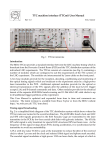
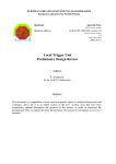
B.G. Taylor
RD12 working document
Rev 2.0
TTC laser transmitter (TTCex, TTCtx, TTCmx) User Manual
Three types of laser transmitter module have been developed by RD12 for TTC signal
distribution at the experiments. The two main modules (see Fig. 1) are single-width 6U
VME size and use only standard VMEbus power supplies. The modules can be used
separately or in combination to match the requirements of a variety of different TTC
distribution architectures.
Fig. 1 TTCex and TTCtx laser transmitter modules
TTCex Encoder/Transmitter
The TTCex module provides 10 optical outputs at a level of about 0 dBm, each of which
can be fanned out by a 1:32 optical tree coupler to broadcast to a total of 320 destinations.
The module contains 2 biphase mark encoders driven by a common internal VCXO/PLL
with very low jitter. It can be operated as a single unit, or in independent halves to feed 2
2
small partitions of up to 160 destinations each. Outputs from the TTCex encoders are
provided to drive extension TTCtx modules to broadcast to larger partitions. The power
consumption of the module is about 16W.
TTCtx Transmitter
The TTCtx module is similar to the TTCex but has 14 optical outputs instead of 10 and
does not contain any encoders. It can be operated in independent halves to feed 2 small
partitions of up to 224 destinations each, or as a single unit to feed a total of 448
destinations. An electrical output is provided to allow several TTCtx modules to be daisychained to broadcast to even larger partitions. Since TTCtx modules do not contain
encoders they must be driven by a TTCex module (or by the encoder in a TTCmi, TTC
minicrate, TTC high power transmitter crate, or the output of an LHCb readout supervisor
switch). The power consumption of the module is about 10W.
Fig. 2 TTCmx laser transmitter module
TTCmx Transmitter
A 3U-high version of the TTCtx laser transmitter module is also available for optional use
in TTCmi or TTC transmitter minicrates and in TTC repeaters for the LHC machine beam
instrumentation. This TTCmx module (Fig. 2) provides 4 optical outputs at a level of
about 0 dBm which can be fanned out by 1:32 tree couplers to feed a total of 128
destinations. In other respects, including the electrical daisy-chain output for larger
numbers of destinations, the TTCmx is similar to a TTCtx module.
3
TTCmx modules are normally driven by the encoder in the TTCmi or TTC transmitter
minicrate, or by the optical receiver in a TTC repeater. In experiments such as ALICE, in
which the 'local trigger crates' are located remotely from the CTP, TTCmx modules may be
used to broadcast the 40.08 MHz bunch clock to them from the TTCmi crate to avoid
ground offset or crosstalk problems.
Electrical I/O connections
The front panel Lemo I/O connectors of the TTCex and TTCtx modules are shown in
Figures 3 and 4. All inputs and outputs are ECL-swing 50-ohm AC-coupled except for the
A and B channel inputs to the TTCex, which are DC-coupled.
Fig. 3 TTCex I/O
Fig. 4 TTCtx I/O
On the TTCex front panel, 'O' indicates an output and 'I' an input socket. When the
module is configured for Single operation the signals CLK1, ENC1, A1 and B1 are
associated with all the optical outputs 1 to 10 and the CLK2, ENC2, A2 and B2 sockets are
not used. When the module is configured for Dual operation, the signals CLK1, ENC1, A1
and B1 are associated with the lower group of optical outputs numbered 6 to 10, while the
signals CLK2, ENC2, A2 and B2 are associated with the upper group of optical outputs 1
to 5.
One of the 40.08 MHz LHC bunch clock outputs from the TTCcf modules in the TTCmi
machine interface crate of the experiment is connected to the CLK input socket of each
TTCex. The clock outputs from the TTCex internal VCXO are provided at the CLK1 and
4
CLK2 sockets, which should be linked to the CLOCK IN sockets of the associated TTCvi
modules.
The CHANNEL A and B outputs from the TTCvi modules should be connected to the A1,
B1 and A2, B2 inputs of the TTCex.
The TTCtx module has only two front panel Lemo connectors. The I/P socket is for the
input of the encoded TTC signal from the ENC1 or ENC2 output sockets of a TTCex, or
the encoder in a TTCmi, TTC minicrate or TTC high power transmitter crate, or the output
of a readout supervisor switch. In applications in which greater timing jitter is acceptable
it can also be driven by the encoder output of a TTCvx module.
The TTCtx can also accept the daisy chain output from another TTCtx module which is
configured for Single operation, or the 40.08 MHz clock output from a TTCcf module if the
TTCtx is being used only for clock distribution. When the module is configured in Single
mode the I/P socket is associated with all the optical outputs 1 to 14. When the module is
in Dual mode it is associated with the lower group of outputs 8 to 14.
The I/O Lemo socket on the TTCtx front panel is an input or an output according to the
configuration of the module. When the module is in Single mode, the socket provides a
buffered output of the input signal for daisy-chaining to additional TTCtx modules. When
the module is in Dual mode, it becomes an input socket for the signal associated with the
upper group of optical outputs 1 to 7.
External clock
The TTC system is designed to continue to deliver a 40.08 MHz clock even when parts of
the distribution system are inoperative. Of course this clock is only synchronised with the
LHC bunch crossings when the full timing distribution chain is operational and at other
times it serves only to keep the electronics at the experiments running.
If the central Faraday Cage timing generators are down the clock is generated at the PCR
transmitter. If the PCR transmitter is off it is generated by the local TTCmi at the
experiment. Finally if the TTCmi is powered off the TTCex modules continue to generate
a 40.08 MHz clock from their internal quartz oscillators.
If desired for test purposes, the TTCex modules can be driven by any other external clock
source of frequency 40.079 MHz ± 50 ppm applied to the CLK input socket. Note that ± 50
ppm is only ± 2 kHz so you cannot use a 40.00 MHz source. An ECL swing signal is
required and the internal termination is 50 Ω to ground, AC coupled.
Lemo cables
During the mid-1990s CERN stores received a consignment of yellow-labelled black Lemo
cables of all lengths which had defective crimping, causing intermittent contacts, and
many of these were distributed before the defect was discovered.
After the manufacturing problem was rectified, the black Lemo cables were fabricated
with green labels instead of yellow ones. Current production is yellow-labelled cables
with a brown sheath. In case any yellow-labelled black cables are suspect, change them
for green-labelled black ones or yellow-labelled brown ones.
5
Internal jumpers
Fig. 5 TTCex in Single mode
Fig. 6 TTCex in Dual mode
Two internal jumpers, ST1 and ST2, allow the TTCex and TTCtx modules to be configured
for Single or Dual operation. There are no jumpers in the TTCmx module, which cannot
be operated in independent halves. Figures 5 and 6 indicate the jumper positions for each
mode of operation for the TTCex module, while Figures 7 and 8 indicate the jumper
positions for the TTCtx.
Fig. 7 TTCtx in Single mode
Fig. 8 TTCtx in Dual mode
All the transmitter modules are fitted with non-hermetic EMI shields held by press studs.
To access the jumpers in either module, carefully remove the shield by prising it from its 6
mounting studs. Be careful not to damage the delicate internal optical fibres while the
module is unprotected.
TTCvi BC Delay adjustment
The TTCvi modules associated with each TTCex receive the 40.08 MHz clock from the
CLK1 and CLK2 outputs of the module. The TTCvi internally delays this clock by an
adjustable time in order that the phases of the internally-generated A and B channel
signals which it delivers to the TTCex can be set correctly, taking into account the
propagation delays of the interconnecting coaxial cables.
This clock delay is adjusted by the BC Delay rotary switch at the top of the front panel of
the TTCvi (see Fig. 9), which should be set when the TTCvi is initially installed or if the
lengths of any of the cables connecting it to the TTCex are changed.
6
Fig. 9 BC Delay switch
To set the BC Delay switch, insert Lemo Y adapters at the CLK1 or CLK2 output and the
appropriate A and B data input sockets of the TTCex to allow these signals to be
monitored with a scope probe. Program a VME loop so that the TTCvi generates internal
triggers at a high rate and adjust the switch such that the signal transitions on the data
channels occur 5.4 ns after the rising edge of the clock, as shown in Fig. 10 (∆t = 5.4 ns).
25 ns
CLOCK OUTPUT
∆t
DATA INPUTS
Fig. 10 BC Delay timing adjustment
The BC Delay switch allows the timing to be adjusted in steps of 2 ns and the switch
position which gives the timing nearest the optimum setting should be chosen.
External trigger source timing
In order to minimise the Level-1 trigger latency, the TTCvi does not resynchronize the
L1A<0> input which it receives from the Central Trigger Processor or other external
trigger source. Hence the timing of the TTCex A data input signal routed through the
TTCvi from its L1A<0> input is not affected by the TTCvi BC Delay switch and it must be
7
adjusted at the external trigger source itself to obtain the correct phasing at the A data
input socket of the TTCex.
25 ns
CLOCK OUTPUT
∆s
∆h
A DATA INPUT
Fig. 11 TTCex A channel timing for external trigger
To set the timing for an external trigger source connected to the TTCvi LIA<0> input,
insert Lemo Y adapters at the CLK1 or CLK2 output and the appropriate A data input
socket of the TTCex to allow these signals to be monitored with a scope probe. Select
L1A<0> trigger input in TTCvi CSR1.
The duration and phasing of the external trigger signal source should be such that the
TTCex A data input signal is valid for a minimum setup time of ∆s = 5.1 ns before the
falling edge of the clock and a minimum hold time of ∆h = 3.4 ns after it. (See Fig. 11).
Outside this interval the A data input signal is a "Don't care".
It should be noted that the L1A<0> input of the TTCvi is AC-coupled, which could result
in a level shift at high data rates. The maximum L1A signal duration should therefore be
chosen to avoid significant DC offset at the highest trigger rate.
VCXO phase
The TTCex has an internal VCXO phase adjustment. Please don't touch it as it is set up on
a test bench and, if you have a problem, twiddling this adjustment is sure to get you in
deeper trouble. Because the phase is set up in a standard way, it is not necessary to make
phase adjustments if you exchange one TTCex module for another.
Optical outputs
The TTCex, TTCtx and TTCmx modules are equipped with precision beryllium coppersleeved nickel-plated zinc front panel sockets for industry-standard ST/PC keyed bayonet
optical connectors such as 3M/Dorran Type FO-6105. Index-matching gel should not be
used. Note that a tiny dust particle or other contaminant can completely block the optical
output and the protective caps supplied should be kept on any unused optical outputs.
Don't touch the ends of the ferrules with fingers or allow them to trail on the floor.
8
Impregnated optical instrument tissues such as "Kodak lens cleaning paper" are
recommended for cleaning.
When the ST receptacles are new the connector ferrules can be quite stiff. In case of low
optical signal level check that they are fully home since the bayonet caps can be locked
before they are completely inserted.
The mean optical signal level at each of the module outputs when transmitting the
encoded TTC signal or the 40.08 MHz clock is typically +1.0 dBm ±1.5 dBm. The port-toport insertion loss of the TTCoc 1:32 optical tree couplers (see Fig. 12) is typically in the
range 14.9 dB to 18.7 dB, with a typical variation in the output levels from the 32 ports of a
given coupler of less than ±1.5 dB.
Fig. 12 TTCoc 1:32 optical tree coupler
When a TTC distribution system is configured, low-value (e.g., 3 dB) ST plug-type optical
attenuators should be inserted as necessary to ensure that the received signal does not
overload the optical receivers used. A mean signal level of -19 dBm ±3 dB is optimal for a
wide range of receivers, such as the Agilent HFBR-2316T photodiode + preamplifier.
Owing to the excellent uniformity of the optical tree couplers it is only necessary to insert
a single attenuator at the root. Optoelectronic receivers which are equipped with AGC,
such as the TrueLight TRR-1B43-000 photodiode + preamplifier, have a large dynamic
range and the use of such fine level-adjusting attenuators is unnecessary.
Optical attenuators
In order to allow for the overall insertion loss (splitting loss + excess loss) of 1:32 optical
tree couplers, the power level at each of the outputs of TTCex, TTCtx and TTCmx
transmitter modules is about 100 times that required by a single receiver.
Fig. 13 20 dB optical attenuator
9
If an output is connected directly to a single receiver for test purposes, a 20 dB optical
attenuator (Fig. 13) should be inserted at the transmitter output to avoid overloading.
Because of modal distribution factors, not all attenuator technologies are appropriate for
this application. Suitable attenuators are available from Bruce Taylor.
When making optical signal level measurements in the TTC systems with a multiwavelength power meter it is important to ensure that the instrument calibration for
1310 nm is selected. Many such instruments also require to be zeroed with the optical
input connector capped before making accurate absolute power measurements.
Optical fibre
All the optical transmitter outputs are intended for operation with ordinary 50/125 µm
graded-index multimode fibre with a numerical aperture of 0.2 and a minimum
bandwidth of 400 MHz.km at 1300 nm. Fibre attenuation at this wavelength is typically
less than 3 dB/km.
For safety reasons, only fibre with a Low-Smoke Zero-Halogen (LSZH) sheath should be
used, although if you employ hot melt connectors you may find the low melting point of
such material an inconvenience. Optical fibre purchase requisitions at CERN are
controlled to enforce the LSZH requirement and if you bring PVC-sheathed fibre to CERN
it may not be permitted at the LHC.
Ready-connectorized multimode optical patchcords for interconnecting the RD12 TTC
distribution modules have been standardised in CERN stores in a range of overall lengths
as follows:
04.67.00.005.9
(L = 0.5 m)
04.67.00.015.7
(L = 1.5 m)
04.67.00.050.4
(L = 5 m)
04.67.00.150.1
(L = 15 m)
04.67.00.500.9
(L = 50 m)
CERN stores do not supply separate optical fibre, connectors or accessories like adapters,
couplings, splices and attenuators. 3M/Dorran Type FO-6112 couplings suitable for
concatenating the patchcords are available from Bruce Taylor.
Laser inhibit
The TTCex, TTCtx and TTCmx transmitter modules are equipped with a front panel
switch which allows all the optical outputs to be disabled. The TTCex and TTCtx lasers
can also be disabled by pulling low the VMEbus SYSFAIL* line. The signal input is
compatible with the VMEbus standard but also has a pull-up so that the modules can be
used in a lower-cost 6U crate with only power supplies and no terminated VME dataway.
In the case of the TTCmx the inhibit facility is available at pin z24 of the module connector
(TTL load with internal pull-up 1K to +5v).
10
A red LED on the front panel indicates when the lasers are active. The hazard level is
Class 1 but output connectors or fibre ends should not be viewed with optical instruments.
Laser characteristics
The transmitter modules use multi-sourced InGaAsP low-threshold MQW hermeticpackage Fabry-Perot lasers rated for operation at 0 to 55 ˚C. The operating wavelength is
1280-1330 nm and the spectral width at -20 dBm is less than 4 nm. They are ITU-T G.957
compliant except for the higher mean launched power.
The laser diodes have temperature-compensated bias and modulation current control and
the output of a rear facet monitor is used to maintain constant optical output level against
temperature changes and device aging. Monitoring of the laser bias current and rear facet
light output is possible internally to the modules for test purposes. Extinction ratio
typically exceeds 13 dB.
Laser replacement
Although lifetime data are not available for the laser transmitters, one TTCtx has been
operating continuously for well over 12 months without measurable degradation of the
signal levels or timing jitter of any of the 14 optical outputs.
All the lasers are mounted in sockets and should one fail it can easily be replaced. The
ESD threshold on all pins is 1000v. The lasers are fitted with a non-standard short pigtail
and it should be noted that there is a special insulator film between each laser and its
socket. Before insertion, the package pins are trimmed precisely using a jig. The lasers
themselves carry individual serial numbers and have a 12 month warranty.
Support contact
In case of any problems with TTCex, TTCtx or TTCmx modules contact:
Bruce Taylor
CERN/EP
[email protected]
Tel: (+4122) 767 3420
TTC website: http://ttc.web.cern.ch/TTC/intro.html
In order to ensure that maintenance will be available throughout the lifetime of the LHC,
support will in due course be provided by EP Division ESS Group.