1
User Guide
Release 2.8.2
March 13, 2012
Pigeon Point Shelf Manager User Guide
© 2002-2012 Pigeon Point Systems. All rights reserved.
Pigeon Point Shelf Manager and ShMM-500 (ShMM-500R), ShMM-500RE, ShMM-1500R
This document is furnished under license and may be used or copied only in accordance with the
terms of such license. The content of this manual is furnished for informational use only, is subject
to change without notice, and should not be construed as a commitment by Pigeon Point Systems.
Pigeon Point Systems assumes no responsibility or liability for any errors or inaccuracies that may
appear in this book.
Except as permitted by such license, no part of this publication may be reproduced, stored in a
retrieval system, or transmitted, in any form or by any means, electronic, manual, recording, or
otherwise, without the prior written permission of Pigeon Point Systems.
The Pigeon Point Shelf Manager uses an implementation of the MD5 Message-Digest algorithm
that is derived from the RSA Data Security, Inc. MD5 Message-Digest algorithm.
The Pigeon Point name and the stylized lighthouse logo, as well as Monterey Linux and
IntegralHPI, are trademarks of Pigeon Point Systems. Linux is a registered trademark of Linus
Torvalds.
Release 2.8.2
2
March 13, 2012
Pigeon Point Shelf Manager User Guide
Table of Contents
1
ABOUT THIS DOCUMENT .................................................................................................... 9
1.1
SHELF MANAGER DOCUMENTATION ................................................................................... 9
1.1.1 Conventions Used in this Document.......................................................................... 9
1.2
ADDITIONAL RESOURCES ................................................................................................ 10
2
INTRODUCTION .................................................................................................................. 11
2.1
IN THIS SECTION ............................................................................................................ 11
2.2
INTELLIGENT PLATFORM MANAGEMENT: AN ATCA OVERVIEW.......................................... 11
2.3
PIGEON POINT BOARD MANAGEMENT REFERENCE: HARDWARE AND FIRMWARE ............... 13
2.4
PIGEON POINT SHELF MANAGER AND SHMM................................................................... 14
2.4.1 Pigeon Point Shelf Manager Features..................................................................... 15
2.4.2 Support for Dual Redundant Operation ................................................................... 15
2.4.3 System Manager Interface....................................................................................... 16
2.4.4 Pigeon Point ShMM Shelf Management Mezzanines ............................................. 17
3
CONFIGURATION................................................................................................................ 20
3.1
IN THIS SECTION ............................................................................................................ 20
3.2
SETTING UP U-BOOT ...................................................................................................... 20
3.2.1 U-Boot Environment Variables ................................................................................ 21
3.2.2 Assigning Values to Environment Variables............................................................ 24
3.2.3 Configuring U-Boot Environment Variables for the Shelf Manager ......................... 25
3.2.4 Establishing the Secondary RC Script..................................................................... 26
3.3
SETTING UP SHELF MANAGER CONFIGURATION FILE ....................................................... 27
3.3.1 Carrier-specific Configuration File ........................................................................... 58
3.3.2 Obtaining Configuration Variables from Shelf FRU Information.............................. 58
3.3.3 Verbosity Level Description ..................................................................................... 59
3.3.4 Verbosity Console Level Description ....................................................................... 60
3.4
SETTING UP ETHERNET .................................................................................................. 60
3.4.1 Usage of the First Ethernet Interface....................................................................... 60
3.4.2 Usage of the Second Ethernet Interface.................................................................. 61
3.4.3 Using the ShMM-500 Alternate Software Redundancy Interface............................ 66
3.4.4 Using the ShMM-1500 Alternate Software Redundancy Interface.......................... 69
3.4.5 Changing the Default ShMM Network Parameters.................................................. 69
3.4.6 Assigning VLAN IDs................................................................................................. 75
3.4.7 Assigning IP Addresses to the Shelf Manager via DHCP ....................................... 76
3.5
CONFIGURING THE FRU INFORMATION ............................................................................ 79
3.5.1 Accessing the Shelf FRU Information...................................................................... 79
3.5.2 Setting up the Shelf FRU Information ...................................................................... 81
3.5.3 Setting up the Shelf FRU Information Using the CLI ............................................... 83
3.5.4 Other FRU Information Repositories ....................................................................... 84
3.6
CONFIGURING CARRIER AND SHELF ATTRIBUTES USING HPDL......................................... 85
3.6.1 Compiling HPDL Definitions .................................................................................... 85
3.6.2 Compiling SDRs....................................................................................................... 86
3.6.3 Deploying HPDL Data to the ShMM File System .................................................... 86
3.6.4 Deploying HPDL Data to FRU Information Areas.................................................... 87
3.7
CONFIGURING THE COOLING MANAGEMENT STRATEGY .................................................... 90
3.7.1 Default Cooling Management Strategy.................................................................... 91
3.7.2 Configuring a Specific Cooling Management Strategy ............................................ 92
3.8
CONFIGURING LOCAL SENSORS ...................................................................................... 93
3.9
SETTING THE AUXILIARY FIRMWARE REVISION ................................................................. 98
3.10
SETTING UP THE CLOCK ................................................................................................. 98
Release 2.8.2
3
March 13, 2012
Pigeon Point Shelf Manager User Guide
3.10.1
Obtaining Date and Time from a Time Server..................................................... 99
3.11
SETTING UP AND USING SHMM POWER ON SELF TESTS ............................................... 101
3.12
CONFIGURING EXTERNAL EVENT HANDLING................................................................... 102
3.12.1
Detailed Steps to Configure External Event Handling....................................... 102
3.12.2
External Event Handler Operation..................................................................... 104
3.13
CONFIGURING THE PLATFORM EVENT TRAP FORMAT ..................................................... 105
3.13.1
Parsed Example of SNMP Trap ........................................................................ 106
3.14
CONFIGURING THE INTEGRALHPI INTERFACE ................................................................. 107
3.14.1
HPI Domain Support in IntegralHPI................................................................... 108
3.14.2
HPI SNMP Subagent Support ........................................................................... 108
3.14.3
IntegralHPI Client Configuration........................................................................ 108
3.15
CONFIGURING SYSTEM SERVICES ................................................................................. 108
4
USING THE SHELF MANAGER........................................................................................ 111
4.1
IN THIS SECTION .......................................................................................................... 111
4.2
SHMM LOGIN ............................................................................................................... 111
4.3
STARTING THE SHELF MANAGER ................................................................................... 111
4.4
REDUNDANT OPERATION .............................................................................................. 119
4.4.1 Initialization of the Redundant Shelf Managers ..................................................... 122
4.4.2 Redundancy and CPLD State Sensor ................................................................... 122
4.4.3 Reboot Reason Sensor ......................................................................................... 124
4.5
OPERATION IN SHELVES WITH RADIAL IPMB-0............................................................... 125
4.5.1 Operation in ShMM-500-based Shelves with Radial IPMB-0 ................................ 125
4.5.2 Operation in ShMM-1500-based Shelves with Radial IPMB-0 .............................. 127
4.6
AUTOMATIC SEL TRUNCATION ...................................................................................... 130
4.7
COOLING STATE SENSORS............................................................................................ 131
4.8
DEADLOCK DETECTION ................................................................................................. 133
4.9
MASTER-ONLY I2C BUS FAULT ISOLATION ..................................................................... 137
4.10
ASSIGNMENT OF LAN CONFIGURATION PARAMETERS TO BOARDS AND MODULES ........... 138
4.10.1
Structure and Composition of the Supported Parameters ................................ 138
4.10.2
Obtaining LAN Configuration Parameters on the Shelf Manager Level............ 138
4.10.3
Dispatching LAN Configuration Parameters to Boards ..................................... 143
4.10.4
Synchronous Assignment of LAN Configuration Parameters to Boards........... 143
4.11
HPI SYSTEM EVENT SENSOR ........................................................................................ 144
4.12
SHMM TESTS AVAILABLE VIA THE DIAGNOSTIC INFRASTRUCTURE .................................. 145
5
USING THE IPMI ANALYSIS TOOLS ............................................................................... 147
5.1
IN THIS SECTION .......................................................................................................... 147
5.2
IPMB TRACE COLLECTION DAEMON (IPMB_TRACED) ..................................................... 147
5.3
IPMI TRACE ANALYZER ................................................................................................ 150
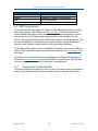
5.3.1 Introduction to the Wireshark GUI ......................................................................... 150
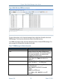
5.3.2 Introduction to Terminal-oriented Wireshark ......................................................... 153
5.3.3 Installing IPMI Analyzer Software .......................................................................... 154
5.4
COLLECTING AND ANALYZING A TRACE USING THE GUI AND COMMAND LINE TOOLS ....... 154
5.4.1 Collecting IPMB Traces in Unattended Mode........................................................ 154
5.4.2 Collecting IPMB Traces in Controlled Mode.......................................................... 159
5.4.3 Collecting an IPMB Trace in Board Trace Mode ................................................... 162
5.4.4 Collecting Traces of IPMI Traffic Over the Network .............................................. 162
5.4.5 Analyzing a Trace Using the GUI .......................................................................... 165
5.4.6 Analyzing a Trace Using Command-Line Tools .................................................... 168
6
RE-INITIALIZING THE SHMM ........................................................................................... 171
6.1
6.2
6.3
6.4
IN THIS SECTION .......................................................................................................... 171
RE-INITIALIZING THE U-BOOT ENVIRONMENT.................................................................. 171
RE-INITIALIZING THE FILE SYSTEM ................................................................................. 172
RESETTING THE LOGIN PASSWORD ............................................................................... 172
Release 2.8.2
4
March 13, 2012
Pigeon Point Shelf Manager User Guide
7
RE-PROGRAMMING THE SHMM ..................................................................................... 174
7.1
IN THIS SECTION .......................................................................................................... 174
7.2
FIRMWARE RELIABLE UPGRADE PROCEDURE OVERVIEW ................................................ 174
7.3
FLASH PARTITIONING .................................................................................................... 175
7.4
THE /VAR/UPGRADE FILE SYSTEM.................................................................................. 180
7.5
RELIABLE UPGRADE PROCEDURE STATUS FILE.............................................................. 180
7.6
RELIABLE UPGRADE UTILITY ......................................................................................... 181
7.7
RELIABLE UPGRADE UTILITY USE SCENARIOS ................................................................ 188
7.8
RELIABLE UPGRADE EXAMPLES..................................................................................... 189
7.8.1 Example 1 .............................................................................................................. 189
7.8.2 Example 2 .............................................................................................................. 192
7.8.3 Example 3 .............................................................................................................. 195
7.9
HPI-BASED SHELF MANAGER UPGRADE ........................................................................ 197
8
CUSTOMER SUPPORT ..................................................................................................... 199
9
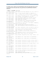
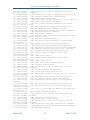
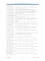
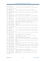
REVISION HISTORY.......................................................................................................... 200
9.1
9.2
9.3
9.4
9.5
9.6
9.7
9.8
9.9
9.10
9.11
9.12
9.13
9.14
9.15
9.16
9.17
9.18
9.19
9.20
9.21
9.22
9.23
RELEASE 2.1.0............................................................................................................. 200
RELEASE 2.2.0............................................................................................................. 200
RELEASE 2.3.0............................................................................................................. 200
RELEASE 2.4.0............................................................................................................. 201
RELEASE 2.4.1............................................................................................................. 201
RELEASE 2.4.2............................................................................................................. 202
RELEASE 2.4.4............................................................................................................. 202
RELEASE 2.5.0............................................................................................................. 202
RELEASE 2.5.2............................................................................................................. 202
RELEASE 2.5.3............................................................................................................. 203
RELEASE 2.6.0............................................................................................................. 203
RELEASE 2.6.1............................................................................................................. 203
RELEASE 2.6.4............................................................................................................. 204
RELEASE 2.6.4.2.......................................................................................................... 204
RELEASE 2.6.4.4.......................................................................................................... 204
RELEASE 2.7.0............................................................................................................. 204
RELEASE 2.7.1............................................................................................................. 205
RELEASE 2.7.2............................................................................................................. 205
RELEASE 2.7.3............................................................................................................. 205
RELEASE 2.7.4............................................................................................................. 205
RELEASE 2.8.0............................................................................................................. 206
RELEASE 2.8.1............................................................................................................. 206
RELEASE 2.8.2............................................................................................................. 206
Release 2.8.2
5
March 13, 2012
Pigeon Point Shelf Manager User Guide
Figures
Figure 1 Management Aspects and Potential Pigeon Point Product Sites in an Example
AdvancedTCA Shelf.............................................................................................................. 12
Figure 2 Pigeon Point Shelf Manager Redundancy Support ........................................................ 16
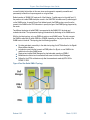
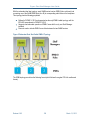
Figure 3 Implementation Options for ShMC Cross-connects........................................................ 65
Figure 4 Dual Star Radial IPMB-0 Topology ............................................................................... 128
Figure 5 Redundant Dual Star Radial IPMB-0 Topology ............................................................ 129
Figure 6 Main Window (IPMB trace analysis) ............................................................................. 151
Figure 7 Main Window (IPMI over network trace analysis) ......................................................... 153
Figure 8 Open Capture File Window ........................................................................................... 156
Figure 9 GUI Main Window (Unattended mode) ......................................................................... 156
Figure 10 Capture Options Window ............................................................................................ 160
Figure 11 Collected Trace (Controlled mode) ............................................................................. 161
Figure 12 Capture Options Window (analyzing networked IPMI traffic)...................................... 163
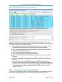
Figure 13 Collected Trace (networked IPMI traffic)..................................................................... 164
Figure 14 Message 244 is Selected ............................................................................................ 166
Figure 15 IPMI Protocol Layers (IPMB trace).............................................................................. 167
Figure 16 Filtered Trace .............................................................................................................. 168
Release 2.8.2
6
March 13, 2012
Pigeon Point Shelf Manager User Guide
Tables
Table 1 Shelf Manager Documentation........................................................................................... 9
Table 2 Conventions Used in this Document .................................................................................. 9
Table 3 ShMM-500R and -1500R Features and Variants............................................................. 18
Table 4 ShMM Models................................................................................................................... 18
Table 5 U-Boot Environment Variables ......................................................................................... 21
Table 6 Configuration Parameter Types and Descriptions ........................................................... 27
Table 7 Shelf Manager Configuration Parameters ........................................................................ 29
Table 8 U-Boot Environment Variables and Descriptions ............................................................. 58
Table 9 Verbosity Configuration Parameters and Levels .............................................................. 60
Table 10 Shelf FRU Information and Configuration Variable Settings .......................................... 81
Table 11 Network Services.......................................................................................................... 109
Table 12 IPMB Topology Record ................................................................................................ 130
Table 13 Cooling State Sensors.................................................................................................. 132
Table 14 ShMM Tests Implemented in the Diagnostic Infrastructure ......................................... 145
Table 15 Options for the IPMB Analyzer Trace Collection Daemon ........................................... 148
Table 16 IPMB Trace Collection Packet Field............................................................................. 149
Table 17 IPMB Message List Basic Information.......................................................................... 151
Table 18 IPMI Filter Primitives..................................................................................................... 167
Table 19 Flash Partitioning for 16MB Flash ShMM-500s............................................................ 175
Table 20 Flash Partitioning for 32MB Flash ShMM-500s............................................................ 176
Table 21 Flash Partitioning for 64MB Flash ShMM-500s............................................................ 177
Table 22 Flash Partitioning for 32MB Flash ShMM-1500s.......................................................... 178
Table 23 Flash Partitioning for 64MB Flash ShMM-1500s.......................................................... 179
Table 24 Standard Source File Names for Upgrade Components.............................................. 183
Release 2.8.2
7
March 13, 2012
Pigeon Point Shelf Manager User Guide
1 About This Document
This document describes the Pigeon Point Shelf Manager. This PDF file requires Adobe Acrobat
Reader 7.0 for full functionality. For a free reader, go to http://www.adobe.com.
1.1 Shelf Manager Documentation
This document is one of two documents in the Shelf Manager documentation set. These
documents are available in PDF file format. The complete set includes:
Table 1 Shelf Manager Documentation
DOCUMENT
Pigeon Point Shelf Manager
User Guide
Pigeon Point Shelf Manager
External Interface Reference
1.1.1
DESCRIPTION
This document describes the overall configuration
and use of the Pigeon Point Shelf Manager.
This document describes how to use the Shelf
Manager command line interface, web interface,
Simple Network Management Protocol (SNMP)
interface and Remote Management Control Protocol
(RMCP) interface.
Conventions Used in this Document
This table describes the textual conventions used in this document.
Table 2 Conventions Used in this Document
CONVENTION SAMPLE
setenv
U-Boot 1.0.2 (Apr 18 2006 14:58:54)
addmisc
“Get Device ID”
Release 2.8.2
DESCRIPTION
This 10 point bold Courier font is used for text
entered at keyboard in example dialogues, which
typically occur as one or more separate lines.
This 10 point normal Courier font is used ShMM
output in example dialogues.
This 12 point bold Courier font is used for special
text within normal paragraphs. The types of such
special text include command names, file
names, configuration parameters and command
parameters, plus other text that could be entered
by or displayed to a Shelf Manager user. This
font is also used for command syntax definitions.
IPMI commands defined by the IPMI
specification or as PICMG extensions are shown
in the normal font, surrounded by double quotes.
This matches the corresponding convention
used in PICMG specifications.
9
March 13, 2012
Pigeon Point Shelf Manager User Guide
1.2 Additional Resources
For more information about Pigeon Point products, go to the Pigeon Point Web site:
http://www.pigeonpoint.com/products.html.
Release 2.8.2
10
March 13, 2012
Pigeon Point Shelf Manager User Guide
2 Introduction
This section provides an overview of the Pigeon Point Shelf Manager and Shelf Management
Mezzanine (or ShMM, currently the ShMM-500R and ShMM-1500R) products. The Pigeon Point
Shelf Manager is a shelf-level management solution for AdvancedTCA® (ATCA®) products.
The Pigeon Point ShMM, when coupled with a corresponding carrier board, provides the necessary
hardware to run the Shelf Manager within an ATCA shelf. This document focuses on aspects of the
Shelf Manager and ShMM that are common to any ShMM carrier used in an AdvancedTCA
context. Carrier-specific and shelf-specific details are documented by shelf providers.
The ShMM-500R complies with the Restriction of Hazardous Substances (RoHS) directive, but is
equivalent to its predecessor, the ShMM-500, from a software point of view. All references to the
ShMM-500 in this document apply to the ShMM-500R, unless otherwise noted. The ShMM-1500R
was designed to be RoHS-compliant from the start and there is no ShMM-1500 product, though
references to the ShMM-1500R may be simplified as ShMM-1500.
The ShMM-1500R is an additional ShMM variant that is based on a PowerPC processor, unlike the
ShMM-500R, which is based on a MIPS-32 processor. The ShMM-1500R also has different
physical dimensions and a different approach for connecting to the ShMM carrier. Therefore,
distinct ShMM carrier boards are required for the Shelf Manager solutions based on the ShMM500R versus the ShMM-1500R. However, the Pigeon Point Shelf Manager provides the same
functionality and high level interfaces for both ShMM variants.
The Pigeon Point Shelf Manager is adaptable to manage CompactPCI platforms as well. This
document focuses primarily on AdvancedTCA contexts, but provides CompactPCI-specific
comments where appropriate.
2.1 In This Section
This section contains the topics listed below. Just click on a topic to go to it.
•
•
•
Intelligent Platform Management: An ATCA Overview
Pigeon Point Board Management Reference: Hardware and Firmware
Pigeon Point Shelf Manager and ShMM
2.2 Intelligent Platform Management: An ATCA Overview
The Pigeon Point products are the first Intelligent Platform Management building blocks designed
from the ground up for modular platforms like AdvancedTCA, in which there is a strong focus on a
dynamic population of Field Replaceable Units (FRUs) and maximum service availability.
The Intelligent Platform Management Interface (IPMI) specification provides a solid foundation for
the management of such platforms, but requires significant extension to support them well.
IPMI defines a management infrastructure that is widely used across the PC and server industry.
PICMG 3.0, the AdvancedTCA specification, defines the necessary extensions to IPMI. PICMG
Release 2.8.2
11
March 13, 2012
Pigeon Point Shelf Manager User Guide
specifications are based on revision 1.5 of IPMI. However, the Pigeon Point Shelf Manager
conforms to revision 2.0 of the IPMI specification and implements numerous IPMI 2.0 features,
including: RMCP+, Virtual LAN support, firmware firewall commands.
PICMG has significantly extended IPMI to cover the needs of open modular architectures. In fact,
about 30% of the 656 pages of PICMG 3.0 are devoted to hardware platform management,
including the definition of 38 new commands, ten new FRU Information data structures—several
quite complex—and 3 new sensor types. The AdvancedMC and MicroTCA specifications add
another 208 pages of hardware platform management coverage.
The strategy for the Pigeon Point Shelf Manager is to fully support these extensions and also map
them to other platform architectures such as CompactPCI.
Note:
AdvancedTCA has adopted the term “shelf” for alignment with typical practice in
telecommunications applications. Traditionally (for instance, in the CompactPCI specifications), the
term “chassis” has been used with essentially the same meaning.
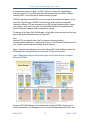
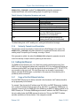
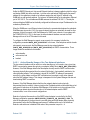
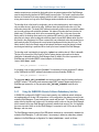
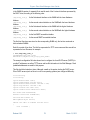
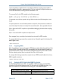
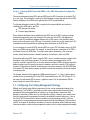
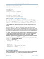
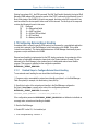
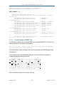
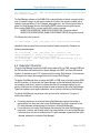
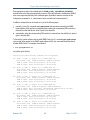
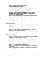
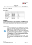
Figure 1 shows the logical elements of an example AdvancedTCA shelf, identified in terms of the
ATCA specification, and potential sites for incorporation of Pigeon Point products.
Figure 1 Management Aspects and Potential Pigeon Point Product Sites in an Example
AdvancedTCA Shelf
An AdvancedTCA Shelf Manager communicates inside the shelf with IPM Controllers, each of
which is responsible for local management of one or more Field Replaceable Units (FRUs), such
Release 2.8.2
12
March 13, 2012
Pigeon Point Shelf Manager User Guide
as boards, fan trays or power entry modules. Management communication within a shelf occurs
primarily over the Intelligent Platform Management Bus (IPMB), which is implemented on a dualredundant basis as IPMB-0 in AdvancedTCA.
The PICMG Advanced Mezzanine Card (AdvancedMC or AMC) specification, AMC.0, defines a
hot-swappable mezzanine form factor designed to fit smoothly into the physical and management
architecture of AdvancedTCA.
Figure 1 includes an AMC carrier with a Carrier IPMC and two installed AMC modules, each with a
Module Management Controller (MMC). On-carrier management communication occurs over
IPMB-L (“L” for Local).
An overall System Manager (typically external to the shelf) can coordinate the activities of multiple
shelves. A System Manager typically communicates with each Shelf Manager over Ethernet.
The next two sections address the board and shelf levels of management, highlighting the following
Pigeon Point products and their capabilities as well as the relevant AdvancedTCA functionality:
•
•
Pigeon Point Board Management Reference firmware and corresponding hardware reference
design, which together implement various types of management controllers.
Pigeon Point Shelf Manager software and ShMM mezzanine module, which, together with an
appropriate ShMM carrier board, implement an AdvancedTCA-compliant Shelf Manager and
Shelf Management Controller (ShMC).
2.3 Pigeon Point Board Management Reference: Hardware and
Firmware
This hardware and firmware level includes the local management of full-size 8U AdvancedTCA
boards as well as other auxiliary FRUs, such as fan trays or power entry modules. Based on the
interfaces specified by IPMI and extended by AdvancedTCA and AdvancedMC, any compliant
Shelf Manager can work with any compliant IPM Controller and the FRUs that it represents,
including AMCs.
This section focuses on controllers based on Pigeon Point technology as a concrete example.
The focus here is on controller solutions for AdvancedTCA and AdvancedMC. Pigeon Point also
provides solutions for MicroTCA management controllers.
The Pigeon Point BMR reference design can be implemented as part of any board or other FRU,
and executes the corresponding firmware, thereby realizing a compliant IPM Controller. The BMR
firmware represents one or more FRUs (via IPMB-0) to the Shelf Manager, including:
•
•
Providing inventory information identifying each such FRU, including its manufacturer and
other data.
Describing and implementing a set of logical sensors (such as for temperature, state of IPMB0, and operational state for each FRU (activated, deactivated, etc.)).
Release 2.8.2
13
March 13, 2012
Pigeon Point Shelf Manager User Guide
•
•
Generating events (typically directed to the Shelf Manager) for exceptional conditions detected
by any sensor, based on its configured event generation settings.
Negotiating with the Shelf Manager for resources needed by the FRU(s), including power and
interconnects.
BMR firmware running on an AMC Carrier IPMC additionally represents its installed AMCs to the
Shelf Manager, including negotiating for power resources on their behalf. Furthermore, a Carrier
IPMC negotiates with its AMCs and on-carrier switching resources regarding interconnect
configurations.
The AMC management architecture is purposely designed to: 1) avoid impacting existing ATCA
Shelf Managers and 2) minimize the resources required to implement a Module Management
Controller, since board real estate and cost are at a premium on AMCs.
There are Pigeon Point BMR variants for AdvancedTCA IPM Controllers, as well as for AMC
Carrier IPMCs and MMCs. Currently, the principal BMR variants are based on the Atmel AVR
ATmega and Renesas H8S/216x microcontroller families, with variants based on Actel Fusion
mixed-signal FPGAs coming soon. Please see http://www.pigeonpoint.com/products.html for more
details on these offerings, as well as on the Pigeon Point solutions for MicroTCA controllers.
Pigeon Point Board Management Starter Kits for each of these BMR variants include all the
materials necessary (documentation, schematics, bill of materials, firmware source code and
development tools, etc.) for Intelligent FRU developers to integrate a reference design directly into
their boards and take immediate advantage of the fully validated BMR firmware.
More details (including product briefs) on the available Pigeon Point BMR variants and
corresponding Starter Kits are available at http://www.pigeonpoint.com/products.html.
2.4 Pigeon Point Shelf Manager and ShMM
The Pigeon Point Shelf Manager (consistent with AdvancedTCA Shelf Manager requirements) has
two main responsibilities
•
•
Manage/track the FRU population and common infrastructure of a shelf, especially the power,
cooling and interconnect resources and their usage. Within the shelf, this
management/tracking primarily occurs through interactions between the Shelf Manager and
the IPM Controllers over IPMB-0.
Enable the overall System Manager to join in that management/tracking through the System
Manager Interface, which is typically implemented over Ethernet.
Much of the Pigeon Point Shelf Manager software is devoted to routine missions such as powering
a shelf up or down and handling the arrival or departure of FRUs, including negotiating
assignments of power and interconnect resources.
In addition, the Shelf Manager can take direct action when exceptions are raised in the shelf. For
instance, in response to temperature exceptions the Shelf Manager can raise the fan levels or, if
that step is not sufficient, even start powering down FRUs to reduce the heat load in the shelf.
Release 2.8.2
14
March 13, 2012
Pigeon Point Shelf Manager User Guide
2.4.1
Pigeon Point Shelf Manager Features
The Pigeon Point Shelf Manager features are listed below:
•
•
•
•
•
•
•
•
•
•
•
Executes on the ShMM, a compact mezzanine module, installed on a suitable carrier board for
the shelf.
Conforms to the AdvancedTCA specification.
Monitors activities within the shelf via the ATCA-specified dual redundant Intelligent Platform
Management Bus (IPMB).
Accepts and logs events posted by any intelligent FRU in the shelf (reflecting exceptions in
temperatures, voltages, etc.); posts alerts outside the shelf based on configurable IPMI
Platform Event Filters.
Supports hot swapping of Field Replaceable Units (FRUs), while maintaining full management
visibility.
Interfaces to standard “Telco Alarm” infrastructures, via ShMM carrier-implemented dry contact
relays.
Supports redundant Shelf Manager instances for high availability.
Integrates a watchdog timer, which resets the ShMM if not periodically strobed; such resets
automatically trigger a switchover to the backup ShMM, if configured.
Includes battery-backed real-time clock for time-stamping events.
Implements rich set of shelf-external interfaces accessible over Ethernet, including Remote
Management Control Protocol (RMCP, required by AdvancedTCA), command line, web
browser, Simple Network Management Protocol (SNMP).
Optionally supports an additional built-in shelf-external interface that complies with the
Hardware Platform Interface (HPI), a set of application programming interfaces (APIs) for
managing hardware platforms that is defined by the Service Availability Forum
(www.saforum.org).
The Pigeon Point Shelf Manager can also be used in CompactPCI shelves.
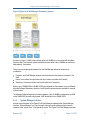
2.4.2
Support for Dual Redundant Operation
The Pigeon Point Shelf Manager can be configured with active/backup instances to maximize
availability.
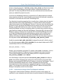
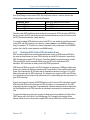
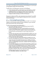
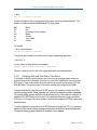
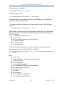
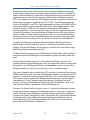
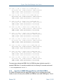
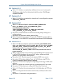
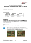
Figure 2 shows how both instances are accessible to the System Manager, with only the active
instance interacting at any given time. Similarly, only the active instance communicates over IPMB0 with the IPM Controller population in the shelf.
The two instances communicate over TCP/IP, with the active instance posting incremental state
updates to the backup ShMMs using either an Ethernet or USB connection between the ShMMs.
As a result, the backup can quickly step into the active role if necessary.
Release 2.8.2
15
March 13, 2012
Pigeon Point Shelf Manager User Guide
Figure 2 Pigeon Point Shelf Manager Redundancy Support
As shown in Figure 2, ShMC cross-connects allow both ShMMs to be connected with both Base
Interface Hubs. This improves system availability because either hubs or ShMMs can switchover
independently, if necessary.
Three cross-connected signals between the two Shelf Manager instances enhance their
coordination:
•
•
•
Presence: each Shelf Manager instance knows whether the other instance is present in the
shelf.
Health: each instance knows whether the other instance considers itself “healthy.”
Switchover: the backup instance can force a switchover if necessary.
When a pair of ShMM-500Rs or ShMM-1500Rs is configured for state updates via a non-Ethernet
Alternate Software Redundancy Interface, both Ethernet interfaces become available for external
communication.
The Alternate Software Redundancy Interface between a pair of ShMMs is implemented via USB
on the ShMM-500R and with a high speed, UART-based link on the ShMM-1500R.
2.4.3
System Manager Interface
Another major subsystem of the Pigeon Point Shelf Manager implements the System Manager
Interface. “System Manager” is a logical concept that may include software as well as human
operators in the “swivel chairs” of an operations center. The Pigeon Point Shelf Manager provides
Release 2.8.2
16
March 13, 2012
Pigeon Point Shelf Manager User Guide
a rich set of System Manager Interface options, which provide different mechanisms of access to
similar kinds of information and control regarding a shelf.
One such mechanism is the IPMI LAN Interface. To maximize interoperability among
independently implemented shelf products, this interface is required by the AdvancedTCA
specification and supports IPMI messaging with the Shelf Manager via the IPMI Remote
Management Control Protocol (RMCP).
A System Manager that uses RMCP to communicate with shelves should be able to interact with
any ATCA-compliant Shelf Manager. This relatively low level interface provides essentially
complete access to the IPMI aspects of a shelf, including the ability for the System Manager to
issue IPMI commands to IPM Controllers in the shelf, using the Shelf Manager as a proxy.
The Pigeon Point Shelf Manager also supports Simple Network Management Protocol (SNMP)
access to the shelf. This popular management protocol is supported with a custom Management
Information Base (MIB) providing Get and Set access to a wide range of information and controls
regarding the shelf.
In addition, the Pigeon Point Shelf Manager provides two interfaces oriented towards human users
rather than programmatic ones:
•
•
Command Line Interface (CLI): This interface provides a comprehensive set of textual
commands that can be issued to the Shelf Manager via either a physical serial connection or a
telnet connection.
Web-based Interface: This interface enables essentially the same functionality as the CLI, with
access to the Shelf Manager via a web browser.
Finally, the Pigeon Point Shelf Manager can optionally include an IntegralHPI subsystem, which
provides access to the Shelf Manager via the Hardware Platform Interface (HPI). IntegralHPI
operates within the Shelf Manager, fully leveraging the Shelf Manager’s facilities for managing the
elements and events in the shelf. IntegralHPI also takes advantage of the mature redundancy
framework of the Shelf Manager to deliver a fully redundant HPI service.
Using these mechanisms, the System Manager can access information about the current state of
the shelf, including current FRU population, sensor values, threshold settings, recent events and
overall shelf health.
These aspects of ATCA’s System Manager Interface are considered to be the Pigeon Point shelfexternal interfaces. They are documented separately in the Shelf Manager External Interface
Reference.
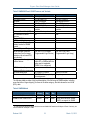
2.4.4
Pigeon Point ShMM Shelf Management Mezzanines
The Pigeon Point Shelf Manager executes on the ShMM, a small Shelf Management Mezzanine
with ShMM-500R and ShMM-1500R variants. Each type of ShMM is available with: 1) 32 Mbytes of
Flash and 64 Mbytes of SDRAM or 2) 64 Mbytes of Flash and 128 Mbytes of SDRAM. The
following table shows the key characteristics of the key ShMM variants.
Release 2.8.2
17
March 13, 2012
Pigeon Point Shelf Manager User Guide
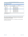
Table 3 ShMM-500R and -1500R Features and Variants
FEATURE
CPU
Processor core(s)
SDRAM
Flash
Ethernet
Serial
Universal Serial Bus (USB)
PCI interface to carrier
devices
Duplex IPMB-0
ATCA watchdog timer
Real-time clock, optionally
battery backed on ShMM
carrier
General Purpose I/O signals
Shelf Manager hardware
redundancy and hot swap
interface, via on-board PLD,
as indicated
High speed interface(s) to oncarrier devices
SHMM-500R
NetLogic Au1550
333 MHz MIPS-32
64 or 128 Mbytes
16 1, 32 or 64 Mbytes
Dual 10/100 Mbit
Two, one with modem
controls
Host and device ports
No
SHMM-1500R
Freescale MPC8343
250 MHz PowerPC
128 Mbytes with EEC
32 or 64 Mbytes
Dual 10/100/1000 Mbit
Two, one with modem
controls
No
Yes
Yes
Yes
Yes
Yes
Yes
Yes
Nine
Yes, via CPLD (Complex
Programmable Logic Device)
Nine
Yes, via FPGA (Field
Programmable Logic Array)
Multiple ports supporting
either SPI or SMBus (with the
latter used to implement
IPMB-0, if so configured)
Yes
SPI
JTAG interface for processor
debug and flash programming
Physical dimensions
67.60mm X 50.80mm
Form factor definition
SO-DIMM-144 w/ proprietary
pin assignments
Yes
92mm x 50.80mm
Proprietary
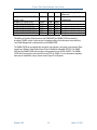
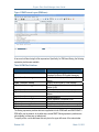
The following table provides a high level description of the full range of ShMM models, including
some that are no longer shipping; for those in the latter category, the table shows the end of life
(EOL) date.
Table 4 ShMM Models
PART #
ShMM-300R (EOL June, 2007)
ShMM-500RE-333M16F32R
PROCESSO FLASH
R SPEED
SIZE
47Mhz
16Mb
333Mhz
16Mb
RAM
SIZE
32Mb
32Mb
COMMENTS
Replaced with ShMM-500R
Entry level variant of ShMM500R; no support for ShMM
For new shipments after about August, 2008, the low-end ShMM-500R model has 32 Mbytes of Flash. Previously, the
low-end model had 16 Mbytes of Flash.
1
Release 2.8.2
18
March 13, 2012
Pigeon Point Shelf Manager User Guide
ShMM-500R-333M16F64R (EOL
August, 2008)
ShMM-500R-333M32F64R
ShMM-500R-333M64F128R
ShMM-1500R-250M32F64R
ShMM-1500R-250M64F128R
ShMM-1500R-250M32F64R-NE
ShMM-1500R-250M64F128R-NE
333Mhz
16Mb
64Mb
333Mhz
333Mhz
250Mhz
250Mhz
250Mhz
250Mhz
32Mb
64Mb
32Mb
64Mb
32Mb
64Mb
64Mb
128Mb
64Mb
128Mb
64Mb
128Mb
redundancy, along with other
differences
Replaced with ShMM-500R333M32F64R
Encryption code present
Encryption code present
Encryption code removed
Encryption code removed
This edition of the User Guide focuses on the ShMM-500R and ShMM-1500R and uses the
shorthand “ShMM” to refer to both variants. A separate edition of this document covers the Entry
Level Shelf Manager that is implemented on the ShMM-500RE.
The ShMM-1500R can be ordered with encryption code present or encryption code removed. Each
variant has a different United States Export Control Classification Number (ECCN). The ShMM500R and the ShMM-1500R with encryption code present have an ECCN of 5A002. The ShMM1500R with the encryption code removed has an ECCN of 5A992. For more information regarding
these export classification topics, please contact Pigeon Point Systems.
Release 2.8.2
19
March 13, 2012
Pigeon Point Shelf Manager User Guide
3 Configuration
The Shelf Manager runs on top of Monterey Linux (http://www.montereylinux.com), a specialized
implementation of Linux for the ShMM-500 and the ShMM-1500. The lowest layer of Monterey
Linux is the firmware monitor, which is called U-Boot on both ShMM variants.
3.1 In This Section
This section contains the topics listed below. Just click on a topic to go to it.
•
•
•
•
•
•
•
•
•
•
•
•
•
Setting Up U-Boot
Setting Up Shelf Manager Configuration File
Setting Up Ethernet
Configuring the FRU Information
Configuring Carrier and Shelf Attributes using HPDL
Configuring the Cooling Management Strategy
Configuring Local Sensors
Setting the Auxiliary Firmware Revision
Setting Up the Clock
Setting Up and Using ShMM Power On Self Tests
Configuring External Event Handling
Configuring the Platform Event Trap Format
Configuring the IntegralHPI Interface
3.2 Setting Up U-Boot
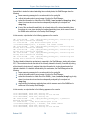
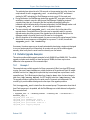
On a power-up/reset of the ShMM, the hardware starts executing the U-Boot firmware in Flash.
The firmware performs basic initialization of the ShMM, and unless the user explicitly disables the
Autoboot feature (thus forcing the firmware to switch to the maintenance user command interface),
commences booting the Linux kernel. Linux is booted from the kernel and root file system images
residing in Flash. U-Boot relocates the kernel image to RAM, sets up kernel parameters, and
passes control to the kernel entry point.
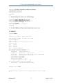
For ShMM-500:
U-Boot 1.1.2 (Apr 27 2005 - 19:17:09)
CPU: Au1550 324 MHz, id: 0x02, rev: 0x00
Board: ShMM-500
S/N: 00 00 00 00 00 00 00 00 00 03 03 03
DRAM: 64 MB
Flash: 16 MB
In:
serial
Out:
serial
Err:
serial
Net:
Au1X00 ETHERNET
Hit any key to stop autoboot: 0
shmm500
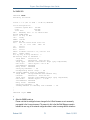
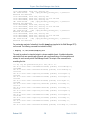
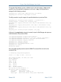
For ShMM-1500:
Release 2.8.2
20
March 13, 2012
Pigeon Point Shelf Manager User Guide
U-Boot 1.1.4 (Jun 15 2006 - 17:49:12) MPC83XX
Clock configuration:
Coherent System Bus:
99 MHz
Core:
249 MHz
Local Bus:
24 MHz
CPU:
MPC83xx, Rev: 1.1 at 249.975 MHz
Board: ShMM-1500R
PCI1: 32 bit, 33 MHz
I2C:
ready
DRAM: 128 MB
FLASH: 64 MB
PCI:
Bus Dev VenId DevId Class Int
00 17 1172 0001 ff00 00
In:
serial
Out:
serial
Err:
serial
FPGA: firmware version 1.12, carrier id 0
Net:
TSEC0, TSEC1
Hit any key to stop autoboot: 0
shmm1500
Note:
“shmm500”and “shmm1500” are U-Boot’s prompts for user commands. For a complete set of
supported commands, type help. In this document, example dialogues that are applicable to both
ShMM variants, represent this prompt with “shmmx500”. Example dialogues that are applicable to
only one of the variants use the relevant prompt.
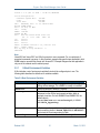
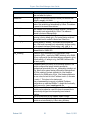
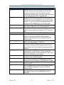
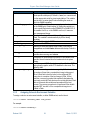
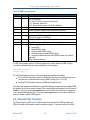
3.2.1
U-Boot Environment Variables
U-Boot includes a set of environment variables that should be configured prior to use. The
following table describes the default set of variables available:
Table 5 U-Boot Environment Variables
ENVIRONMENT VARIABLE
addmisc
baudrate
bootargs
bootcmd
bootdelay
Release 2.8.2
DESCRIPTION
Appends quiet, reliable_upgrade and console
settings to bootargs. This variable is normally not modified.
Serial port baud rate, default is 115200.
Command line to be passed to the Linux kernel. May contain
references to other U-Boot environment variables, which is
resolved at run-time. On both ShMM-500 and ShMM-1500, the
default value is:
root=/dev/ram rw console=ttyS0,115200
reliable_upgrade=y.
U-Boot command executed to accomplish auto-booting. Normally,
this is something similar to bootm BFB00000 BFC40000,
which starts the Linux image stored in Flash.
Autoboot delay value, in seconds. Default setting is 3.
21
March 13, 2012
Pigeon Point Shelf Manager User Guide
ENVIRONMENT VARIABLE
bootfile
console
ethaddr
eth1addr
flash_reset
gatewayip
hostname
io_config
ipaddr
ip1addr
ip1device
kernel_start
Release 2.8.2
DESCRIPTION
Parameter that specifies what kernel image should be used by the
net and nfs boot options.
Setting for the kernel and init script console port and baud rate.
Default is ttyS0,115200.
MAC address of the primary on-chip Ethernet controller. The
value of this variable is set automatically by U-Boot. This address
is passed to the kernel Ethernet driver.
MAC address of the secondary Ethernet controller. The value of
this variable is set automatically by U-Boot. This address is
passed to the kernel Ethernet driver.
Instructs Linux to erase the flash filesystems (/etc and /var),
restoring to factory default (y/n). The system startup script sets
this variable back to n after the flash erase. Default is n.
Default gateway IP address. This variable can be passed as a
part of the kernel command line to automatically configure routing
for the network interfaces. Default setting: 192.168.0.1.
Network host name; default is shmm500 for ShMM-500 and
shmm1500 for ShMM-1500.
ShMM-500 only: Determines if the Programmable Serial
Controllers (PSCs – used for the IPMB-0 interface) on the ShMM500 are configured for the dual-slave-address-configuration (y/n).
Default setting: y. If setting is not y, the IPMB-0 interface does
not work properly
IP address used by the primary on-chip Ethernet interface. This
variable configures the network interface specified by
ipdevice automatically if the rc_ifconfig variable is set
to y. Note that the system startup script sets the least significant
bit of this variable to the least significant bit of the Hardware
Address for the ShMM carrier; that is, if the Hardware Address is
an even value, the last bit in the IP address is set to 0, otherwise
it is set to 1. This is done in the startup script
/etc/netconfig to support coordinated IP address
configurations on redundant ShMMs. To disable this functionality,
simply remove the /etc/readhwaddr file.
IP address used by the secondary Ethernet interface. This
variable can be passed as a part of the kernel command line to
automatically configure the corresponding kernel network
interface.
Device corresponding to $ip1addr; eth1 is default.
The absolute starting address of the kernel image in Flash. This
variable is set automatically by U-Boot during bootstrap.
22
March 13, 2012
Pigeon Point Shelf Manager User Guide
ENVIRONMENT VARIABLE
log_max
log_remote
logging
net
netmask
nfs
password_reset
post_normal
post_poweron
quiet
ramargs
ramdisk
ramsize
rc_ifconfig
Release 2.8.2
DESCRIPTION
Specifies the size limit for the syslog file in bytes. Default is
250000. When the log file size reaches the limit, the file is
renamed as a backup file, and a new syslog file is started
(replacing any existing backup), so that the maximum space used
by the overall syslog is twice the log_max value.
Specifies the IP address for the remote syslog facility. By default,
this option is not set. The syslog daemon on Linux systems can
be configured to receive messages from remote hosts, normally
using the -r option, so using the log_remote setting it is
possible to send the ShMM system log to a remote system.
Specifies if messages log file should be maintained in ram or
flash. Default is ram, which is the recommended option.
This variable can be used as a replacement for bootcmd as a
means of booting a kernel and rfs image from TFTP. Use run
net.
Network netmask, default value is 255.255.255.0
This variable can be used as a replacement for bootcmd as a
means of booting and running with an NFS mounted root
filesystem. See the Monterey Linux User Guide sample NFS
project for details
Instructs Linux to restore factory default password for user “root”
(which is the empty password “”). Default is n.
Determines the list of POST tests that are executed on each bootup. If not set, compile-time default settings are used. The test
names listed in a value of this variable are separated by space
characters.
Determines the list of POST tests that are executed after poweron reset only (vs. on each boot-up). If not set, compile-time
default settings are used. The test names listed in a value of this
variable are separated by space characters.
Instructs the kernel upon bootup not to print progress messages
to the serial console. Default is quiet.
Sets the kernel command line in the bootargs variable as
appropriate for the root filesystem to be mounted from a ramdisk.
Specifies what .rfs image should be used by the net and
nfs boot options.
Size of the system memory, in bytes. Default setting: calculated
from the SDRAM configuration encoding in the build-time
configuration block.
Allows the /etc/rc script to set up the IP address instead of
shelfman. Default is n (allow shelfman to set up IP
addresses).
23
March 13, 2012
Pigeon Point Shelf Manager User Guide
ENVIRONMENT VARIABLE
rc2
DESCRIPTION
Specifies secondary RC script that is to be invoked. This is the
carrier-specific startup script. Default is /etc/rc.carrier3
or other appropriate script for given target platform. This variable
must be set to a carrier-specific value matching the carrier on
which the ShMM is installed.
reliable_upgrade
Determines if the reliable software upgrade procedure is enabled
on the ShMM (y/n). Default setting: y. Setting this variable to n
is not currently supported on either ShMM-500 or ShMM-1500. If
the variable is set to n, on the ShMM’s next boot, it issues an
error message and hangs.
rfs_start
The absolute starting address of the root filesystem image in
Flash. This variable is set automatically by U-Boot during
bootstrap.
rmcpaddr
Default IP address for the RMCP service.
serverip
IP address of the TFTP server
start_rc2_daemons Instructs the secondary startup script to start or not start the
snmpd/boa and shelfman daemons after bootup. Default is
y.
time_proto
Protocol used to retrieve time from a network time server;
possible values are ntp and rdate.
time_server
Time server for synchronization at runtime. If this variable is not
specified, time is extracted from the hardware clock at system
startup.
timezone
Local time zone in CCCn format where n is the offset from GMT
and optionally negative, while CCC identifies the time zone. The
default is UTC.
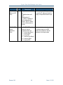
corrupted_images
This self-incrementing counter is managed by U-Boot to record
the number of times that a corrupted boot image is discovered.
When U-Boot fails to boot the kernel or the configured RFS
image, due to corruption of the boot image in Flash, U-Boot
executes a recovery procedure that essentially designates the
previously provisional Flash device as the current persistent Flash
device, increments this variable and proceeds with the boot
process. The recovery procedure is not performed if the reliable
upgrade WDT is active or if the corrupted boot image is not
located in Flash.
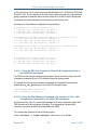
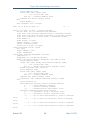
3.2.2
Assigning Values to Environment Variables
To assign a value to an environment variable, on either ShMM variant, use the format:
shmmx500 setenv <variable_name> <new_value>
For example:
shmmx500 setenv bootdelay 1
Release 2.8.2
24
March 13, 2012
Pigeon Point Shelf Manager User Guide
Once all of the environment variables have been properly set, you need to save them back out to
the Flash so that they remain after the ShMM is powered down. The saveenv command is used
for this purpose.
shmmx500 saveenv
The setenv functionality is also available as a Linux utility with the same usage. To display UBoot variables at the shell prompt, use the additional getenv utility or issue the setenv
command without parameters.
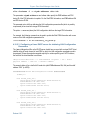
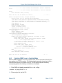
3.2.3
Configuring U-Boot Environment Variables for the Shelf Manager
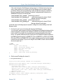
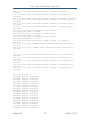
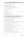
When U-Boot is started for the first time, the following default environment variables are defined.
For ShMM-500:
addip=setenv bootargs $(bootargs)
ip=$(ipaddr):$(serverip):$(gatewayip):$(netmask):$(hostname):$(ipdevice)
addmisc=setenv bootargs $(bootargs) $(quiet)
console=$(console),$(baudrate) reliable_upgrade=$(reliable_upgrade)
bootargs=root=/dev/ram rw console=ttyS0,115200 reliable_upgrade=y
bootcmd=run ramargs addmisc; bootm $(kernel_start) $(rfs_start)
bootdelay=3
bootfile=sentry.kernel
baudrate=115200
console=ttyS0
ethaddr= 00:00:1a:18:xx:yy
eth1addr= 00:00:1a:18:xx:zz
netmask=255.255.0.0
hostname=shmm500
gatewayip=192.168.0.1
ipdevice=eth0
ip1addr=192.168.1.2
ip1device=eth1
rc2=/etc/rc.carrier3
ipaddr=192.168.0.22
start_rc2_daemons=y
flash_reset=n
password_reset=n
logging=ram
net= tftpboot 80400000 $(bootfile); tftpboot 81200000 $(ramdisk);
run ramargs addmisc; bootm 80400000 81200000
nfs=tftpboot 80800000 $(bootfile); run nfsargs addip addmisc;
bootm
nfsargs=setenv bootargs root=/dev/nfs rw
nfsroot=$(serverip):$(rootpath)
quiet=quiet
rc_ifconfig=n
ramargs=setenv bootargs root=/dev/ram rw
ramdisk=sentry.rfs
reliable_upgrade=y
rootpath=/rootfs
rmcpaddr=192.168.0.2
serverip=192.168.0.7
Release 2.8.2
25
March 13, 2012
Pigeon Point Shelf Manager User Guide
timezone=UTC
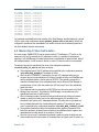
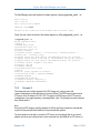
For ShMM-1500:
addip=setenv bootargs $(bootargs)
ip=$(ipaddr):$(serverip):$(gatewayip):$(netmask):$(hostname):$(ipdevice)
addmisc=setenv bootargs $(bootargs) $(quiet)
console=$(console),$(baudrate) reliable_upgrade=$(reliable_upgrade)
bootargs=root=/dev/ram rw console=ttyS0,115200 reliable_upgrade=y
bootcmd=run ramargs addmisc; bootm $(kernel_start) $(rfs_start)
bootdelay=3
bootfile=sentry.shmm1500.kernel
baudrate=115200
console=ttyS0
ethaddr= 00:50:c2:3f:xx:yy
eth1addr= 00:50:c2:3f:xx:zz
netmask=255.255.0.0
hostname=shmm1500
gatewayip=192.168.0.1
ipdevice=eth0
ip1addr=192.168.1.2
ip1device=eth1
rc2=/etc/rc.carrier3
ipaddr=192.168.0.22
start_rc2_daemons=y
flash_reset=n
password_reset=n
logging=ram
net= tftpboot 400000 $(bootfile); tftpboot 1200000 $(ramdisk); run
ramargs addmisc; bootm 400000 1200000
nfs=tftpboot 400000 $(bootfile); run nfsargs addip addmisc; bootm
nfsargs=setenv bootargs root=/dev/nfs rw
nfsroot=$(serverip):$(rootpath)
quiet=quiet
rc_ifconfig=n
ramargs=setenv bootargs root=/dev/ram rw
ramdisk=sentry.shmm1500.rfs
reliable_upgrade=y
rootpath=/rootfs
rmcpaddr=192.168.0.2
serverip=192.168.0.7
timezone=UTC
Several of these environment variables need to be reconfigured with values that are appropriate to
the network context in which the ShMM is used.
3.2.4
Establishing the Secondary RC Script
The secondary RC script gets invoked when the system configuration is established during the
boot process. It is called from the primary RC script /etc/rc. The secondary script is a carrierspecific startup script and is /etc/rc.carrier3 by default or some other script that is
appropriate for that platform. A typical name for this script is
/etc/rc.<target_platform>.
Release 2.8.2
26
March 13, 2012
Pigeon Point Shelf Manager User Guide
The name of this carrier-specific startup script is defined by the U-Boot environment variable rc2.
The variable rc2 is the one environment variable that must definitely be changed for a ShMM and
its carrier to work properly in a shelf.
The RC2 script sets up environment variables CARRIER and CARRIER_OPTIONS. These
variables inform the Shelf Manager about the carrier on which it is installed and define carrierspecific options as necessary for each supported carrier. By default, the values of these
environment variables are propagated to the corresponding configuration variables (see Table 7
Shelf Manager Configuration Parameters) CARRIER and CARRIER_OPTIONS. The
configuration variables, in their turn, are retrieved and used by the Shelf Manager.
The U-Boot variable start_rc2_daemons instructs the secondary startup script to start or
not start the daemons snmpd (SNMP server), boa (HTTP server) and shelfman (the Shelf
Manager) after Monterey Linux boots. If the U-Boot variable start_rc2_daemons is set to
y, the secondary RC script should also define command-line options for automatic invocation of
the shelfman daemon. It may also provide other configuration services.
3.3 Setting Up Shelf Manager Configuration File
The Shelf Manager configuration file (shelfman.conf) is located in the /etc directory.
Each line in the file is either a comment line (starting with #) or a <name> = <value> pair,
representing the assignment for the configuration parameter. The name and the value are
separated with the equal sign =.
The configuration parameter name is case-insensitive. Each configuration parameter is one of the
following types: Boolean, number, string, or IP-address. The values of string type of configuration
parameters are case-sensitive. The format of the value conforms to the type of the configuration
parameter as shown in the following table.
Table 6 Configuration Parameter Types and Descriptions
CONFIGURATION PARAMETER
TYPE
Boolean
Number
String
IP-address
Release 2.8.2
DESCRIPTION
A Boolean can be represented by either the strings FALSE
(false) or TRUE (true), or by their numerical
representations of 0 and 1, respectively.
A whole (possibly signed) numeric value; hexadecimal notation
“0x…” is also supported.
A string, quoted (always with double quotes “”) or unquoted.
Quoted strings may contain blanks; unquoted strings are
terminated by the first blank. The maximum string size is specified
separately for each string-oriented configuration parameter.
These values are case-sensitive.
An Internet Protocol address in decimal-dot (“xxx.xxx.xxx.xxx”)
notation.
27
March 13, 2012
Pigeon Point Shelf Manager User Guide
It is possible to specify a value of an environment variable as a configuration parameter value,
using the notation $ <envvar>; in that case, the value of the variable <envvar> is substituted
when the configuration file is read. Here is an example:
DEFAULT_RMCP_IP_ADDRESS = $IPADDR
After the Shelf Manager has been brought up for the first time, the IP addresses are stored with the
IPMI LAN configuration parameters. The LAN configuration parameters can be accessed or
modified via any of the RMCP, CLI, web, or SNMP external interfaces and take precedence over
the shelfman configuration file when the Shelf Manager is restarted. This is to ensure the
persistency of any modifications that are made to the LAN IP Addresses and gateway via those
interfaces.
If the Shelf Manager IP Connection record in the Shelf FRU Information contains an IP address, it
takes precedence over all other settings of the external or RMCP IP address. Preferably, the Shelf
FRU Information should either not specify this address at all or set it to 0.0.0.0 to ensure that
addresses can be controlled through the Shelf Manager configuration file and the IPMI LAN
configuration parameters. The value of 0.0.0.0 for an IP-address type of configuration
parameter is interpreted as ‘undefined’.
The Shelf FRU Information should specify the RMCP IP address; the Shelf Manager uses it and
propagates it to the LAN configuration parameters. RMCP is available in the absence of the Shelf
FRU Information only if the configuration parameter RMCP_WITHOUT_SHELF_FRU is defined
and set to TRUE. In this case, the Shelf Manager uses the IP address stored in the channel
parameters. If there are no stored channel parameters, it uses the IP address specified in the boot
parameters of the ShMM.
Some Shelf Manager configuration variables can get their values from the Shelf FRU Info. This
may be useful to users who need to associate certain configuration parameters with a specific
instance of a shelf. In that case, even if ShMMs or ShMM carriers are moved between shelves, the
configuration parameters specified in the Shelf FRU Information stay with the shelf and override
the parameter values specified in configuration files on the ShMM.
If the same variable is specified in a configuration file on the ShMM and in the Shelf FRU
Information, the value from the Shelf FRU Information overrides the value from configuration files.
Note that configuration files are parsed early during the Shelf Manager initialization, while the Shelf
FRU can be found substantially later.
Not all variables can be specified in the Shelf FRU Information; the main reason is that many
variables control the Shelf Manager initialization behavior, which happens before the Shelf FRU
Information is found. For such variables, overriding the value when the Shelf FRU Information is
found, could not have any effect, since the choice they control has typically already been made. If
such variables are specified in the Shelf FRU Information, they are parsed successfully but value
assignments are silently ignored.
Release 2.8.2
28
March 13, 2012
Pigeon Point Shelf Manager User Guide
The configuration variable
SHELF_MANAGER_CONFIGURATION_IN_SHELF_FRU_INFO controls whether this
functionality of the Shelf Manager is enabled. By default, the value of this variable is FALSE and
the functionality is disabled.
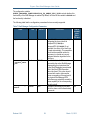
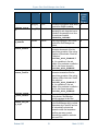
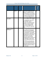
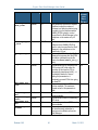
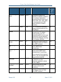
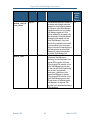
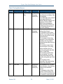
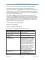
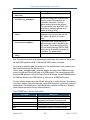
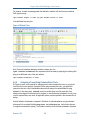
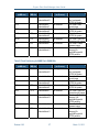
The following table lists the configuration parameters that are currently supported.
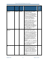
Table 7 Shelf Manager Configuration Parameters
NAME
TYPE
DEFAULT
DESCRIPTION
CAN BE
OBTAINED
FROM
SHELF
FRU INFO
2_X_SYSTEM
Boolean
None
ACTIVATE_LOCAL
_WITHOUT_SHELF
_FRU
Boolean
FALSE
ALARM_CUTOFF_T
IMEOUT
Number
600
Release 2.8.2
If specified, this parameter explicitly
No
designates the current shelf as
CompactPCI (if TRUE) or
AdvancedTCA (if FALSE). If not
specified, the choice of the shelf type
is made automatically. This parameter
should not be specified unless it is
necessary to override an incorrect
hardware detection algorithm for the
shelf type.
If set to TRUE, both IPM controllers
No
exposed by the active Shelf Manager
(representing the physical and the
logical Shelf Managers) are activated
even if the Shelf FRU Information
cannot be found. This option should
be used with caution, because the
power consumption of the payload of
the physical Shelf Manager IPM
controllers may potentially exceed the
power capability of the corresponding
slot in the shelf.
The alarm cutoff timeout (time after
Yes
which the alarm cutoff is deactivated),
in seconds.
29
March 13, 2012
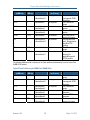
Pigeon Point Shelf Manager User Guide
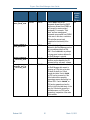
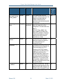
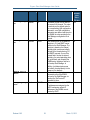
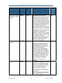
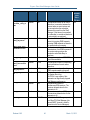
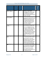
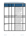
NAME
TYPE
DEFAULT
DESCRIPTION
CAN BE
OBTAINED
FROM
SHELF
FRU INFO
ALLOW_ALL_COMM
ANDS_FROM_IPMB
Boolean
FALSE
ALLOW_CHANGE_E
VENT_RECEIVER
Boolean
TRUE
ALLOW_CLEARING
_CRITICAL_ALAR
M
Boolean
FALSE
ALLOW_POWER_UN
RELATED_FRU_IN
_CRITICAL_STAT
E
Boolean
FALSE
Release 2.8.2
If set to TRUE, most of the
commands allowed from the RMCP
interface are allowed from IPMB-0 as
well (except for session-related
commands). For example, “Cold
Reset” and user management
commands are accepted from IPMB-0
in this case. In this case, a malicious
IPM controller can seriously
jeopardize the functionality of the
shelf.
If set to TRUE, the Event receiver
address for the Shelf Manager can be
set to an address other than 20h,
LUN 0. If set to FALSE, any attempt
to change event receiver address for
the Shelf Manager is rejected.
If set to TRUE, the critical alarm
condition can be cleared by the CLI
command clia alarm clear.
This variable affects the behavior of
the Shelf Manager with respect to
powering up FRUs that are in state
M3 when the shelf is in Critical
thermal alert state. If set to TRUE,
the FRU can be powered on if the
Critical alert state is caused by
temperature sensors that belong to a
different FRU. If set to FALSE, no
FRU can be powered up when the
shelf is in the Critical alert state. In the
case of a Critical alert caused by a
shelf-wide sensor, no FRU can be
powered up, irrespective of the value
of this variable.
30
Yes
Yes
Yes
Yes
March 13, 2012
Pigeon Point Shelf Manager User Guide
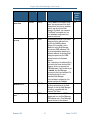
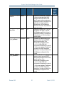
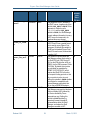
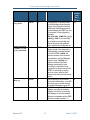
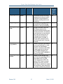
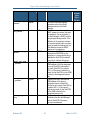
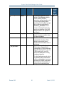
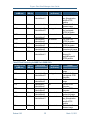
NAME
TYPE
DEFAULT
DESCRIPTION
CAN BE
OBTAINED
FROM
SHELF
FRU INFO
ALLOW_RESET_ST
ANDALONE
Boolean
FALSE
ALTERNATE_CONT
ROLLER
Boolean
TRUE
ATCA_TESTER_CO
MPATIBILITY
Boolean
FALSE
AUTO_SEND_MESS
AGE
Boolean
TRUE
Release 2.8.2
If set to TRUE, the command “Cold
Reset” is accepted even if the Shelf
Manager does not have an available
backup, and reboots the Shelf
Manager. By default, the command
“Cold Reset” is accepted only in a
dual redundant configuration and
causes a switchover.
Use alternate controller on the Shelf
Manager with the address that is
equal to the ShMM hardware
address. If this variable is set to
TRUE, the active Shelf Manager
exposes two IPMB addresses: 20h
and a second address based on its
hardware address; the backup Shelf
Manager exposes only the IPMB
address based on its hardware
address.
After a switchover, the address 20h is
exposed by the former backup Shelf
Manager, which now exposes two
IPMB addresses. If this variable is set
to FALSE, the Shelf Manager
exposes only the logical address 20h,
this is allowed only for a nonredundant Shelf Manager.
In the redundant configuration, this
variable must be set to TRUE.
This variable, if set, turns off event
handling optimizations in the Shelf
Manager, so that the Shelf Manager
behavior is compatible with the
Polaris ATCA Tester.
Automatically convert an RMCP
request sent to a non-Shelf Manager
IPMB address into a “Send Message”
request directed to that address.
31
Yes
No
No
No
March 13, 2012
Pigeon Point Shelf Manager User Guide
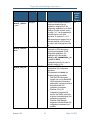
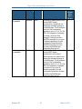
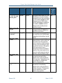
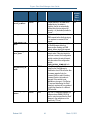
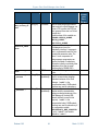
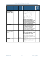
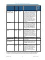
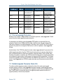
NAME
TYPE
DEFAULT
DESCRIPTION
CAN BE
OBTAINED
FROM
SHELF
FRU INFO
BOARD_LAN_PARA
METERS_CHANNEL
_LIST
String(64)
“”
BOARD_LAN_PARA
METERS_SYNCHRO
NOUS
String(256)
“”
BOARD_LAN_PARA
METERS_USE_DHC
P
Boolean
FALSE
Release 2.8.2
The list of IPMI channel numbers on
Yes
boards and modules that are
available for assignment of LAN
configuration parameters by the Shelf
Manager. Channel numbers, each in
the range 1 to 7, can be separated by
commas, spaces or any other
separators, for example: 3,4,5.
LAN parameters are assigned only to
channels specified in this list and in
the order in which they appear in this
list.
This string value represents the list of Yes
descriptors for FRUs that require
synchronous assignment of LAN
configuration parameters. It is
meaningful only if the variable
BOARD_LAN_PARAMETERS_US
E_DHCP is TRUE.
The detailed syntax for this value is
defined in section 4.10.4.
Yes
If TRUE, use DHCP to retrieve
board/module LAN configuration
parameters.
If this parameter is FALSE, the
following options are available:
• If the Shelf FRU Information
contains one or more Board/AMC
LAN Configuration Parameters
multirecords, use these to retrieve
the board/module LAN
configuration parameters.
• Otherwise, if the LAN
configuration parameters file
exists on the ShMM, use this file
to retrieve the board/module LAN
configuration parameters.
• Otherwise, Shelf Manager
assignment of board/module LAN
configuration parameters is not
available.
32
March 13, 2012
Pigeon Point Shelf Manager User Guide
NAME
TYPE
DEFAULT
DESCRIPTION
CAN BE
OBTAINED
FROM
SHELF
FRU INFO
CARRIER
String(16)
“PPS”
CARRIER_OPTION
S
String(256)
Variable
CONSOLE_LOGGIN
G_ENABLED
Boolean
FALSE
COOLING_FAN_DE
CREASE_TIMEOUT
Number
0
COOLING_FAN_IN
CREASE_TIMEOUT
Number
0
COOLING_IGNORE
_LOCAL_CONTROL
Boolean
FALSE
COOLING_KEEP_P
OWERED_OFF_FRU
S_IN_M1
Boolean
FALSE
Release 2.8.2
The name of the specific carrier board
on which the ShMM is installed.
The carrier-specific options; defined
separately for each supported carrier.
By default, this parameter is set from
the environment variable
$CARRIER_OPTIONS.
Output log messages to the console
on which the Shelf Manager was
started.
The minimum timeout between
successive decrements of the fan
speed during operation of the cooling
algorithm in Normal state. Should be
a multiple of
COOLING_POLL_TIMEOUT; if
not, it is rounded up to the next
multiple. If the parameter is omitted or
set to 0, this timeout is equal to
COOLING_POLL_TIMEOUT.
The minimum timeout between
successive increments of the fan
speed during operation of the cooling
algorithm in Minor Alert state. Should
be a multiple of
COOLING_POLL_TIMEOUT; if
not, it is rounded up to the next
multiple. If the parameter is omitted or
set to 0, this timeout is equal to
COOLING_POLL_TIMEOUT.
Do not use local control capabilities
on fan devices; Shelf Manager
explicitly manages the fan level.
If set, the FRUs that are powered off
by the Shelf Manager due to a critical
temperature stay in state M1 and are
not automatically activated and
powered on when the temperature
condition goes away; manual
intervention is needed to reactivate
each such FRU.
33
No
No
No
Yes
Yes
No
Yes
March 13, 2012
Pigeon Point Shelf Manager User Guide
NAME
TYPE
DEFAULT
DESCRIPTION
CAN BE
OBTAINED
FROM
SHELF
FRU INFO
COOLING_NO_POW
ER_DOWN_IN_CRI
TICAL_ALERT
Boolean
FALSE
COOLING_MANAGE
MENT
String(64)
“”
(undefined)
COOLING_POLL_T
IMEOUT
Number
30
CPLD_ACTIVE_WO
RKAROUND
Boolean
TRUE
CTCA_FRU_RESET
_TIMEOUT
Number
500
Release 2.8.2
34
Do not power down FRUs that
experience critical thermal alerts. This
mode is not compliant with the
PICMG 3.0 (Advanced TCA)
specification and should be used with
extreme caution.
If specified, the name of the shared
library that implements cooling
management. The actual name of the
library is
libcooling_<xxx>.so,
where <xxx> is the value of this
configuration parameter. This library
is dynamically loaded by the Shelf
Manager and must be located in
/var/bin or /lib.
The maximum time (in seconds)
between successive invocations of
the cooling monitoring and
management thread.
This flag (when TRUE) enables a
special workaround to detect the loss
of the Active signal in the CPLD.
(Registers in the CPLD (Complex
Programmable Logic Device) on the
ShMM expose the state of the
hardware redundancy signals to the
software.) This loss may happen on
some platforms when hot inserting a
ShMM carrier. The workaround can
be turned off by setting this value to
FALSE, if this problem does not exist
for a specific platform.
CompactPCI shelves only. The time
in milliseconds during which the Shelf
Manager holds the BD_SEL# line low
in order to reset a CompactPCI board.
Yes
No
Yes
No
No
March 13, 2012
Pigeon Point Shelf Manager User Guide
NAME
TYPE
DEFAULT
DESCRIPTION
CAN BE
OBTAINED
FROM
SHELF
FRU INFO
CTCA_HEALTHY_T
IMEOUT
Number
0
CTCA_INITIAL_F
AN_LEVEL
Number
15
DEFAULT_GATEWA
Y_IP_ADDRESS
IP-address
None
DEFAULT_GATEWA
Y_IP_ADDRESS2
IP-address
None
Release 2.8.2
CompactPCI shelves only. The time
in seconds during which the Shelf
Manager waits for the HEALTHY#
signal to appear when powering on a
CompactPCI board. If the HEALTHY#
signal does not appear within the
specified time, the Shelf Manager
deactivates the board. 0 (the default)
stands for “infinity”.
CompactPCI shelves only. The initial
fan speed (in the range 0..15) that
Shelf Manager applies to fan trays in
CompactPCI shelves. 0 corresponds
to the slowest, and 15 to the fastest
possible speed.
The default IP address used for the
gateway for shelf-external (RMCPbased) communication, if the
corresponding parameter is set to
0.0.0.0 in the IPMI LAN
Configuration Parameters for channel
1. If a non-zero gateway IP address is
provided in the LAN Configuration
Parameters, the value provided in the
Shelf Manager configuration file is
ignored.
The default IP address used for the
gateway for shelf-external (RMCPbased) communication on the second
network interface, if the
corresponding parameter is set to
0.0.0.0 in the IPMI LAN
Configuration Parameters for channel
2. If a non-zero gateway IP address is
provided in the LAN Configuration
Parameters, the value provided in the
Shelf Manager configuration file is
ignored.
35
No
No
No
No
March 13, 2012
Pigeon Point Shelf Manager User Guide
NAME
TYPE
DEFAULT
DESCRIPTION
CAN BE
OBTAINED
FROM
SHELF
FRU INFO
DEFAULT_RMCP_I
P_ADDRESS
IP-address
None
DEFAULT_RMCP_I
P_ADDRESS2
IP-address
None
Release 2.8.2
The default IP address used for shelfexternal (RMCP-based)
communication; it is switched over
between the redundant instances of
the Shelf Manager. This IP address is
used only if the corresponding
parameter is set to 0.0.0.0 in the
IPMI LAN Configuration Parameters
for channel 1 and in the Shelf
Manager IP Connection record in
Shelf FRU Information. If a non-zero
IP address is provided in the LAN
Configuration Parameters and/or
Shelf FRU Information, the value
provided in the Shelf Manager
configuration file is ignored.
The default IP address used for shelfexternal (RMCP-based)
communication on the second
network interface; it is switched over
between the redundant instances of
the Shelf Manager. This IP address is
used only if the corresponding
parameter is set to 0.0.0.0 in the
IPMI LAN Configuration Parameters
for channel 2. If a non-zero IP
address is provided in the LAN
Configuration Parameters, the value
provided in the Shelf Manager
configuration file is ignored.
36
No
No
March 13, 2012
Pigeon Point Shelf Manager User Guide
NAME
TYPE
DEFAULT
DESCRIPTION
CAN BE
OBTAINED
FROM
SHELF
FRU INFO
DEFAULT_RMCP_N
ETMASK
IP-address
Variable
DEFAULT_RMCP_N
ETMASK2
IP-address
Variable
DEFAULT_VLAN_I
D
Number
0
Release 2.8.2
The network mask for the network
No
adapter used for RMCP
communication. This mask is used
only if the corresponding parameter is
set to 0.0.0.0 in the IPMI LAN
Configuration Parameters for channel
1 and in the Shelf Manager IP
Connection record in Shelf FRU
Information. The default value
depends on the class of the default IP
address used for the gateway for
shelf-external (RMCP-based)
communication. (see parameter
DEFAULT_RMCP_IP_ADDRESS
). For example, for an IP address of
class C, this parameter is set to
255.255.255.0
The network mask for the second
No
network adapter used for RMCP
communication. This mask is used
only if the corresponding parameter is
set to 0.0.0.0 in the IPMI LAN
Configuration Parameters for channel
2. The default value depends on the
class of the default IP address used
for the gateway for shelf-external
(RMCP-based) communication. (see
parameter
DEFAULT_RMCP_IP_ADDRESS
2). For example, for an IP address of
class C, this parameter is set to
255.255.255.0
The default Virtual LAN ID used for
Yes
the first LAN channel. This value is
used only as the default value for the
corresponding LAN configuration
parameter; once LAN configuration
parameters are defined and stored on
the ShMM, the value provided in the
Shelf Manager configuration file is
ignored.
37
March 13, 2012
Pigeon Point Shelf Manager User Guide
NAME
TYPE
DEFAULT
DESCRIPTION
CAN BE
OBTAINED
FROM
SHELF
FRU INFO
DEFAULT_VLAN_I
D2
Number
0
DETECT_DEADLOC
KS
Boolean
TRUE
DEVICE_POLL_TI
MEOUT
Number
10
DHCP_FOR_RMCP_
ONLY
Boolean
FALSE
Release 2.8.2
The default Virtual LAN ID used for
the second LAN channel. This value
is used only as the default value for
the corresponding LAN configuration
parameter; once LAN configuration
parameters are defined and stored on
the ShMM, the value provided in the
Shelf Manager configuration file is
ignored.
This variable turns on the deadlock
detection in CLI and RMCP server
facilities in the Shelf Manager. The
detection is based on the internal
watchdog that must be periodically
strobed by the threads serving CLI
and RMCP requests. If one of the
threads fails to strobe the internal
watchdog, the actual watchdog does
not get strobed, and ultimately the
ShMM resets, initiating a failover to
the backup Shelf Manager. In
addition, lock data structures are
periodically checked directly for the
presence of a deadlock.
The time (in seconds) between
successive polls of the IPMB-0
devices by the Shelf Manager via
sending the “Get Device ID”
command to them.
If this variable is set, only the RMCP
IP addresses are assigned via the
DHCP mechanism; private IP
addresses of the ShMMs are not
touched by DHCP.
38
Yes
No
Yes
Yes
March 13, 2012
Pigeon Point Shelf Manager User Guide
NAME
TYPE
DEFAULT
DESCRIPTION
CAN BE
OBTAINED
FROM
SHELF
FRU INFO
DHCP_SERVER_AD
DRESS
IP-address
None
DHCP_SPECIAL_C
LIENT_ID_FORMA
T
Boolean
FALSE
ENABLE_DIRECT_
SHELF_FRU_WRIT
E
Boolean
FALSE
ENABLE_INTEGRA
LHPI
Boolean
FALSE
Release 2.8.2
This parameter is the IP address of
the DHCP server; it applies only if the
variable USE_DHCP is TRUE. If this
parameter is omitted or set to
0.0.0.0, and the USE_DHCP
variable is TRUE, the Shelf Manager
accepts address information from any
DHCP server that responds to its
broadcast discovery request.
If this parameter is set to TRUE, the
DHCP Client ID has a special format
that is used by some Pigeon Point
customers. By default this variable is
FALSE and a standard Pigeon Point
Client ID format is used, as described
in section 3.4.7.
This variable controls whether the
Shelf Manager allows direct writes to
the Shelf FRU Info (FRU Device ID
#254 on the IPM controller at 20h on
IPMB-0) via the IPMI command “Write
FRU Data”. By default, direct writes
are prohibited (as mandated by
PICMG 3.0 R2.0 ECN-002, which
requires that Shelf FRU Info writes
use a special locking protocol so that
only one writer is active at once).
Setting this variable to TRUE enables
direct writes for compatibility with
System Manager applications that
rely on the pre-ECN-002 behavior.
This variable determines whether the
Shelf Manager exposes the Hardware
Platform Interface (HPI) defined by
the Service Availability Forum
(www.saforum.org). Setting this
variable to TRUE enables the
separately licensed IntegralHPI
implementation within the Shelf
Manager, and makes the Shelf
Manager accessible via HPI.
39
Yes
Yes
No
No
March 13, 2012
Pigeon Point Shelf Manager User Guide
NAME
TYPE
DEFAULT
DESCRIPTION
CAN BE
OBTAINED
FROM
SHELF
FRU INFO
EXIT_IF_HEALTH
Y_LOST_IN_STAN
DALONE_MODE
Boolean
FALSE
EXIT_IF_NO_SHE
LF_FRU
Boolean
FALSE
EXTERNAL_EVENT
_HANDLER
String(255)
“”
FAN_FULL_SPEED
_DELAY
Number
0
FAN_LEVEL_STEP
_DOWN
Number
1
FAN_LEVEL_STEP
_UP
Number
1
Release 2.8.2
This variable defines what to do if the
Shelf Manager runs without backup
and detects a loss of the local Healthy
bit. If this variable is TRUE, the Shelf
Manager exits, the ShMM reboots
and the Shelf Manager is restarted. If
this variable is FALSE, the Shelf
Manager sets the Healthy bit and
continues operation
If TRUE, the Shelf Manager exits
(probably resetting the ShMM) if no
Shelf FRU can be found.
This is the path to an executable file
(or a script file) on the Shelf Manager
that performs local handling of events
via PEF.
The delay in seconds after Shelf
Manager startup or after a switchover,
during which the cooling algorithm
does not check the number of present
fan trays, giving the existing fan trays
enough time to activate. This applies
to the carriers where cooling
management raises the fan speed to
maximum if the actual number of fan
trays in the shelf is fewer than what is
specified in the Shelf Address Table.
The number of fan steps by which the
fan speed is decreased during
operation of the cooling algorithm in
the Normal state. This parameter may
be overridden by a ShMM carrierspecific cooling algorithm.
The number of fan steps by which the
fan speed is increased during
operation of the cooling algorithm in
the Minor Alert state. This parameter
may be overridden by a carrierspecific cooling algorithm.
40
Yes
No
No
No
Yes
Yes
March 13, 2012
Pigeon Point Shelf Manager User Guide
NAME
TYPE
DEFAULT
DESCRIPTION
CAN BE
OBTAINED
FROM
SHELF
FRU INFO
HPDL
Boolean
FALSE
HPDL_ON_SUBSID
IARY_FRUS
Boolean
FALSE
HPDL_NETWORK_E
LEMENT_ID_EEPR
OM_OFFSET
Number
0
Release 2.8.2
Turns on HPDL support in the Shelf
No
Manager. The carrier and chassis
HPDL data and SDRs are taken from
the FRU Information or from the files
and are used to define the behavior of
the platform, plus the number and
types of managed FRUs and sensors.
Turns on support of HPDL information Yes
stored on subsidiary FRUs. If TRUE,
the Shelf Manager looks for HPDL
data and SDRs in the FRU
Information of its subsidiary FRUs. If
these data are found for a specific
FRU, they are used to substitute
definitions for that FRU from the
carrier or chassis HPDL data and/or
SDRs.
If non-zero, specifies the offset to the Yes
Network Element ID data structure in
Shelf FRU Information EEPROMs.
This 33-byte data structure consists of
the three separate 11-byte Network
Element IDs and is transparent for the
Shelf Manager but can be read and
modified with CLI commands. A
positive value of this parameter
indicates the offset from the beginning
of the EEPROM, a negative value
means the offset from the end of the
EEPROM. Zero value indicates the
absence of the Network Element ID.
This parameter makes sense only for
HPDL-based systems and only if local
EEPROMs are used to store Shelf
FRU Information.
41
March 13, 2012
Pigeon Point Shelf Manager User Guide
NAME
TYPE
DEFAULT
DESCRIPTION
CAN BE
OBTAINED
FROM
SHELF
FRU INFO
IGNORE_FAILED_
DIRECTED_POWER
_DOWN
Boolean
TRUE
INITIALIZATION
_SCRIPT
String(256)
“”
INITIAL_FAN_LE
VEL
Number
15
Release 2.8.2
This parameter tells the Shelf
Yes
Manager to ignore board power down
failure(s) during a Critical Alert and
not to power down all boards in the
shelf in this case. This parameter also
instructs the Shelf Manager to ignore
board power level decrease failure(s)
during a Major Alert and not to
decrease power level for all boards in
the shelf in this case. If this parameter
is FALSE, all boards in the shelf are
powered down, if board(s) that
caused the Critical Alert cooling state
fail to power off; also, the power level
for all boards in the shelf is
decreased, if decreasing power level
fails for board(s) that caused the
Major Alert cooling state.
This parameter specifies a command No
line that is executed by the active
Shelf Manager during initialization.
This initialization script can perform
additional platform-specific
initialization of the Shelf Manager;
when it is started, the Local Healthy
and Active bits in CPLD are already
set. The Shelf Manager waits for the
completion of the initialization script.
The initialization script is run only
during the startup of the Shelf
Manager; it is not run after a
switchover.
This parameter specifies the initial fan No
level that the Shelf Manager applies
to fan trays. Usually fan level values
are in 0.15 range, where 0 is the
slowest, and 15 is the fastest
possible fan speed. This parameter
has an alias
CTCA_INITIAL_FAN_LEVEL
for CompactPCI shelves.
42
March 13, 2012
Pigeon Point Shelf Manager User Guide
NAME
TYPE
DEFAULT
DESCRIPTION
CAN BE
OBTAINED
FROM
SHELF
FRU INFO
INITIAL_SLOW_L
INK_DELAY
Number
0
INNER_SEQUENCE
_NUMBER_IN_SEN
D_MSG_RESPONSE
Boolean
TRUE
INTEGRALHPI_DO
MAIN_ID
Number
1
IPMB_ADDRESS
Number
0
Release 2.8.2
The initial delay, in seconds, before
the Shelf Manager starts testing the
integrity of the physical network link
between the Shelf Manager and the
System Manager (the RMCP link; see
the description of the configuration
parameter
SWITCHOVER_TIMEOUT_ON_B
ROKEN_LINK). A non-zero delay
can be used to accommodate slow
network links that need significant
time to initialize after shelf power up.
This variable controls which sequence
number is used in the response to a
“Send Message” command bridged
from LAN to IPMB. If TRUE, the
sequence number of the command
encapsulated in the Send Message
request is used. If FALSE, the
sequence number of the Send
Message request itself is used.
According to a clarification being
proposed for the latest version of the
PICMG 3.0 specification, the first
variant is correct, while the Shelf
Manager historically used the second
variant.
The HPI domain ID of the current
shelf; used to differentiate, on the HPI
client level, among multiple shelves
whose Shelf Managers support HPI.
The IPMB address of the Shelf
Manager, overriding the hardware
address. The value of 0 causes the
Shelf Manager to read the hardware
address from hardware and set IPMB
address to hardware address * 2.
43
Yes
No
No
No
March 13, 2012
Pigeon Point Shelf Manager User Guide
NAME
TYPE
DEFAULT
DESCRIPTION
CAN BE
OBTAINED
FROM
SHELF
FRU INFO
IPMB_LINK_ISOL
ATION_TIMEOUT
Number
-1
IPMB_RETRIES
Number
3
IPMB_RETRY_TIM
EOUT
Number
0
IPMB_RETRY_TIM
EOUT_MSEC
Number
500
IPMC_PRESERVE_
ON_REVISION_CH
ANGE
Boolean
TRUE
ISOLATE_MUX_AD
DRESS
Number
0x70
Release 2.8.2
In radial shelves, if an IPMB link is
disabled due to the isolation
algorithm, the link is automatically
enabled after this time interval (in
seconds). –1 (the default) stands for
“forever”.
The number of attempts to send an
IPMB request before finally giving up,
if no response is received to this
request.
The amount of time (in seconds) that
the Shelf Manager waits for a
response after sending an IPMB
request, before retrying the request.
The millisecond part of the retry
timeout value. If the retry timeout is
less than a second, this configuration
variable contains the actual timeout,
while the value of the configuration
variable
IPMB_RETRY_TIMEOUT is 0.
Setting this variable to TRUE
preserves the Shelf Manager’s
identification of an IPM controller after
a firmware upgrade if only the
Firmware Revision and/or Auxiliary
Firmware Revision information is
changed. If the variable is set
FALSE, any change in “Get Device
ID” response data during the Shelf
Manager’s regular polls is considered
to signal the presence of a different
IPM controller.
The 7-bit I2C multiplexer address (on
platforms where SHMM_GPIO8 is
used to control access from the Shelf
Manager to the multiplexer on the
master-only I2C bus).
44
Yes
No
No
No
Yes
No
March 13, 2012
Pigeon Point Shelf Manager User Guide
NAME
TYPE
DEFAULT
DESCRIPTION
CAN BE
OBTAINED
FROM
SHELF
FRU INFO
ISOLATE_MUX_IG
NORE_COUNT
Number
10
ISOLATE_MUX_ON
_GPIO8
Boolean
FALSE
LOCAL_SHELF_FR
U
Boolean
TRUE
M7_TIMEOUT
Number
-1
MAX_ALERT_POLI
CIES
Number
64
MAX_ALERT_STRI
NGS
Number
64
MAX_DEFERRED_A
LERTS
Number
32
MAX_EVENT_FILT
ERS
Number
64
MAX_EVENT_SUBS
CRIBERS
Number
64
Release 2.8.2
This parameter instructs the isolation
algorithm to skip this number of
accesses to a faulty bus before trying
to enable it (on the platforms where
SHMM_GPIO8 is used to control
access from the Shelf Manager to the
multiplexer on the master-only I2C
bus).
Must be set to TRUE for the
platforms where SHMM_GPIO8 is
used to control access from the Shelf
Manager to the multiplexer on the
master-only I2C bus.
Create a local FRU #1 on the Shelf
Manager that exposes the Shelf FRU
Information (obtained from the file
/var/nvdata/shelf_fru_i
nfo).
The maximum time (in seconds) for a
FRU to stay in M7 state; after the
expiration of this time the FRU is
automatically transitioned to M0. –1
(the default) stands for “forever”.
Setting this parameter to 0
completely prevents FRUs from going
into state M7.
The maximum number of PEF Alert
Policies available. The maximum
allowed value for this parameter is
128.
The maximum number of PEF Alert
Strings available.
The maximum number of outstanding
PEF alerts.
The maximum number of PEF event
filters available.
The maximum number of entities that
can simultaneously subscribe to
receive event notifications from the
Shelf Manager.
45
No
No
No
Yes
No
No
No
No
No
March 13, 2012
Pigeon Point Shelf Manager User Guide
NAME
TYPE
DEFAULT
DESCRIPTION
CAN BE
OBTAINED
FROM
SHELF
FRU INFO
MAX_EVENT_SUBS
CRIBER_IDLE_TI
ME
Number
60
MAX_INCOMING_I
PMB_REQUESTS
Number
128
MAX_NODE_BUSY_
TRANSMISSIONS
Number
255
MAX_OEM_FILTER
S
Number
16
MAX_PENDING_EV
ENT_NOTIFICATI
ONS
Number
1024
MAX_PENDING_IP
MB_REQUESTS
Number
192
MAX_SEL_ENTRIE
S
Number
1024
MAX_SESSIONS
Number
32
MAX_USERS
Number
32
MICRO_TCA
Boolean
FALSE
Release 2.8.2
The maximum timeout for an event
subscriber, in seconds, between the
moment when an event arrives and
the moment when the subscriber
retrieves this event from the Shelf
Manager. If this timeout is exceeded,
the subscriber is considered dead and
is automatically unregistered.
The size of the internal Shelf Manager
queue for incoming IPMB requests.
Incoming IPMB requests are stored in
this queue before processing.
The maximum number of
transmissions of an IPMB command if
the receiver always returns the
completion code Node Busy in
response.
The maximum number of PEF OEM
event filters available.
The maximum number of outstanding
event notifications for each active
subscriber.
The maximum number of pending
IPMB requests awaiting response.
The maximum number of entries in
the System Event Log.
CAUTION: Large values of this
parameter can significantly degrade
Shelf Manager performance.
The maximum number of
simultaneous IPMI sessions. The
maximum allowed value for this
parameter is 64.
The maximum number of IPMI users.
The maximum allowed value for this
parameter is 64.
If TRUE, the Shelf Manager operates
as a MicroTCA Shelf Manager (the
second RMCP channel is used for
interaction with Carrier Managers).
46
Yes
No
Yes
No
No
No
No
No
No
No
March 13, 2012
Pigeon Point Shelf Manager User Guide
NAME
TYPE
DEFAULT
DESCRIPTION
CAN BE
OBTAINED
FROM
SHELF
FRU INFO
MIN_FAN_LEVEL
Number
1
MIN_SHELF_FRUS
Number
2
NORMAL_STABLE_
TIME
Number
3600
NO_M0_M1_EVENT
_AT_STARTUP
Boolean
FALSE
PEF_USE_KEYED_
ALARMS
Boolean
FALSE
Release 2.8.2
The minimum fan level; the cooling
management code does not reduce
the fan level of any fan below this
value when controlling the fan level
automatically
The minimum number of Shelf FRUs
in the shelf that the Shelf Manager
must detect to start up successfully.
The time in seconds for which the
Shelf Manager preserves the
minimum fan level dynamically found
in Normal mode (that is, the minimum
fan level that does not cause thermal
alerts). After this time expires, the
cooling algorithm decreases the
minimum fan level, if possible, to
allow the shelf to decrease the fan
level if the thermal load in it has also
decreased.
If TRUE, the physical Shelf Manager
does not send an M0->M1 hot swap
event when the Shelf Manager
application is restarted on the ShMM;
the event is sent only the first time
after the ShMM is plugged into a
shelf. The default value is FALSE for
backward compatibility.
If TRUE, the Shelf Manager uses
special methods of managing TELCO
alarms raised via PEF as OEM
actions. Each event condition that
causes a TELCO alarm is counted
separately in this case, so that if a
specific alarm is raised due to multiple
event conditions, it stays raised while
any of these conditions stay asserted.
47
Yes
No
Yes
No
No
March 13, 2012
Pigeon Point Shelf Manager User Guide
NAME
TYPE
DEFAULT
DESCRIPTION
CAN BE
OBTAINED
FROM
SHELF
FRU INFO
PET_FORMAT
Number
0
PET_OEM_WITH_S
EVERITY_STRING
Boolean
FALSE
POWER_UNLISTED
_FRUS
Boolean
TRUE
PROPAGATE_RMCP
_ADDRESS
Boolean
FALSE
Release 2.8.2
Specifies the format of the Platform
Event Traps that are sent by the Shelf
Manager as the Alert action initiated
by event processing in the Platform
Event Filtering facility. The values are
defined as follows:
0 = the default IPMI format defined by
IPMI Platform Event Trap Format v1.0
specification.
1 = plain text format; all the event
details are sent as plain ASCII text in
a single variable.
2 = multi-variable format; each event
field is encoded as a separate
variable.
If TRUE, the event severity and alert
string is added to a trap message in
the PPS OEM (Plain Text and MultiVariable) PET formats. The default
IPMI PET format always includes
these fields from the corresponding
event filter.
Allow the FRUs not listed in the power
management table in the Shelf FRU
Information to be activated and
powered up.
If TRUE, the active Shelf Manager
propagates the RMCP IP address to
the backup Shelf Manager, which
configures the network interface
specified by the
RMCP_NET_ADAPTER variable
using that IP address, but with the
least significant bit inverted.
48
Yes
No
No
Yes
March 13, 2012
Pigeon Point Shelf Manager User Guide
NAME
TYPE
DEFAULT
DESCRIPTION
CAN BE
OBTAINED
FROM
SHELF
FRU INFO
REAPPLY_POWER_
MAX_COOLING_ST
ATE
String(16)
“NORMAL”
REDUNDANCY_COM
PRESSION_THRES
HOLD
Number
-1
REDUNDANCY_ENA
BLED
Boolean
TRUE
REDUNDANCY_NET
_ADAPTER
String(16)
“”
(undefined)
REDUNDANCY_NET
_ADAPTER2
String(16)
“”
(undefined)
Release 2.8.2
49
Sets the most severe shelf thermal
state in which the Shelf Manager can
power a FRU up after that FRU has
been powered down due to a Critical
thermal alert.
Possible values of this variable are
NORMAL, MINOR_ALERT,
MAJOR_ALERT,
CRITICAL_ALERT.
This parameter controls compression
of messages sent over the
redundancy interface. A message is
sent in compressed format if its size
exceeds the parameter value. The
value -1 turns compression off.
Using message compression can
improve the speed of redundancy
information transfer on relatively slow
redundancy links (like the serial
interface used on ShMM-1500).
Run the Shelf Manager in redundant
mode.
The name of the network adapter
used for communication between
redundant instances of the Shelf
Manager. "usb0" is the
recommended value if USB network
interfaces are used for redundancy.
The name of the second network
adapter used for communication
between redundant instances of the
Shelf Manager (if the dual USB
network interface is used for this
purpose). "usb1" is the
recommended value if USB network
interfaces are used for redundancy. If
the configuration variable
REDUNDANCY_NET_ADAPTER
is set to "usb0", this variable
defaults to "usb1".
No
No
No
No
No
March 13, 2012
Pigeon Point Shelf Manager User Guide
NAME
TYPE
DEFAULT
DESCRIPTION
CAN BE
OBTAINED
FROM
SHELF
FRU INFO
REDUNDANCY_NET
MASK
IP-address
0.0.0.0
REDUNDANCY_POR
T
Number
1040
REDUNDANT_IP_A
DDRESS
IP-address
None
RESERVATION_RE
TRIES
Number
10
RMCP_NET_ADAPT
ER
String(16)
“eth0”
RMCP_NET_ADAPT
ER2
String(16)
None
RMCP_WITHOUT_S
HELF_FRU
Boolean
FALSE
RUN_HPI_SNMP_S
UBAGENT
Boolean
FALSE
SDR_READ_RETRI
ES
Number
3
Release 2.8.2
The netmask to assign to the
redundancy IP address; by default (if
0), the netmask is determined
automatically from the class of the IP
address. 255.255.255.128 is
the recommended value if USB
network interfaces are used for
redundancy.
The TCP port used for interactions
between redundant instances of the
Shelf Manager.
The IP address used for redundant
communications. This address
actually specifies a pair of IP
addresses that differ only in the least
significant bit. They are assigned to
redundant Shelf Managers according
to their hardware addresses.
The maximum number of times the
Shelf Manager retries the “Reserve
Device SDR” command.
The name of the network adapter
used for RMCP-based
communication.
The name of the alternate network
adapter used for RMCP-based
communications, if cross-connect
links are supported by the hardware.
"eth1" is the recommended value
if the parameter is specified.
RMCP is available in the absence of
the Shelf FRU only if this
configuration parameter is defined
and set to TRUE.
Specifies whether the HPI SNMP
subagent should be started
automatically.
The maximum number of times the
Shelf Manager retries the “Read
Device SDR” command.
50
No
No
No
Yes
Yes
Yes
No
No
Yes
March 13, 2012
Pigeon Point Shelf Manager User Guide
NAME
TYPE
DEFAULT
DESCRIPTION
CAN BE
OBTAINED
FROM
SHELF
FRU INFO
SEL_FILE_COMPR
ESSION_ENABLED
Boolean
TRUE
SEL_FILE_JOURN
ALING_ENABLED
Boolean
TRUE
SEL_FILE_WRITE
_DELAY
Number
3
SEL_HIGH_WATER
MARK
Number
0
SEL_LOW_WATERM
ARK
Number
0
Release 2.8.2
If TRUE, the Shelf Manager
compresses the SEL before writing it
to the ShMM flash; this reduces the
size of the file that is periodically
written to the flash and thus increases
the lifetime of the flash.
If TRUE, the Shelf Manager uses
journaling when writing the SEL to the
ShMM flash; this reduces the size of
the data periodically written to the
flash and thus increases the lifetime
of the flash. The reduction is even
greater if SEL compression is
simultaneously enabled.
The minimum number of seconds
between subsequent updates of the
SEL file on the ShMM flash. Setting
this number to a higher value causes
SEL updates to be less frequent; this
reduces the total amount of data
written to the flash and thus increases
the lifetime of the flash, but increases
the probability of event loss if both
redundant Shelf Managers go out of
service.
This value is the “high watermark” for
the algorithm that controls automatic
purging of the SEL; if the actual
percentage of free entries in the SEL
falls below this value, or the SEL
overflows, the Shelf Manager starts a
thread that purges old records from
the SEL in order of decreasing age.
This value is the “low watermark” for
the algorithm that controls automatic
purging of the SEL; if the thread that
purges old records from the SEL
starts, it purges records until the
percentage of occupied entries in the
SEL falls below this value.
51
No
No
No
Yes
Yes
March 13, 2012
Pigeon Point Shelf Manager User Guide
NAME
TYPE
DEFAULT
DESCRIPTION
CAN BE
OBTAINED
FROM
SHELF
FRU INFO
SENSOR_POLL_IN
TERVAL
Number
1
SESSION_SEQUEN
CE_WINDOW
Number
128
SHELF_FRU_IN_E
EPROM
Boolean
TRUE
SHELF_FRU_IPMB
_SOURCE1
Number
0
SHELF_FRU_IPMB
_SOURCE2
Number
0
SHELF_FRU_TIME
OUT
Number
5
Release 2.8.2
The time (in seconds) between
successive polls of local Shelf
Manager sensors by the Shelf
Manager.
This is the window of acceptable
RMCP sequence numbers; the wider
this window is, the more tolerant is
the Shelf Manager to RMCP packets
being dropped during transfer. If the
difference in the sequence numbers
of a received packet and the previous
packet exceeds the window size, the
Shelf Manager closes the RMCP
session as a corrupted one.
If TRUE, the Shelf FRU Information is
retrieved from EEPROMs on the
backplane in a carrier-specific way; if
FALSE, the Shelf FRU is obtained
from a file on the flash file system.
If defined (non-zero), specifies the
IPMB address of the first designated
source of Shelf FRU Information in
the shelf. (Shelf FRU is located at
FRU 1.) If this value is defined, the
search for the Shelf FRU on the IPMB
is limited to the designated sources
only.
If defined (non-zero), specifies the
IPMB address of the second
designated source of Shelf FRU
Information in the shelf. (Shelf FRU is
located at FRU 1.) If this value is
defined, the search for the Shelf FRU
on the IPMB is limited to the
designated sources only.
The time interval (in seconds) during
initialization that the Shelf Manager
waits for Shelf FRU Information
devices to be detected.
52
No
No
No
No
No
No
March 13, 2012
Pigeon Point Shelf Manager User Guide
NAME
TYPE
DEFAULT
DESCRIPTION
CAN BE
OBTAINED
FROM
SHELF
FRU INFO
SHELF_MANAGER_
CONFIGURATION_
IN_SHELF_FRU_I
NFO
Boolean
FALSE
SHORT_SEND_MSG
_RESPONSE
Boolean
TRUE
SPECIAL_HPI_EN
TITY_FOR_AMC_C
ARRIER
Boolean
TRUE
SWAPPED_CROSS_
CONNECTS
Boolean
FALSE
Release 2.8.2
If TRUE, instructs the Shelf Manager
to retrieve configuration parameters
from a special set of records in the
Shelf FRU Information. If these
parameters are successfully retrieved,
they override the values from
configuration files. Not all
configuration variables can be
overridden from the Shelf FRU
Information; for example, this variable
cannot be overridden (for obvious
reasons) and, to be effective, must be
specified in the configuration file.
Determines the type of the “Send
Message” response provided by the
Shelf Manager: required by the
current PICMG 3.0 (if TRUE) or
compatible with the previous versions
of the Shelf Manager (if FALSE).
If TRUE, IntegralHPI uses the entity
type
SAHPI_ENT_SUBBOARD_CARR
IER_BLADE for AMC carrier
boards; otherwise the entity type
SAHPI_ENT_PICMG_FRONT_B
LADE is used.
Swaps the names of network
adapters used for cross-connects on
the ShMC with the odd hardware
address.
53
No
No
No
Yes
March 13, 2012
Pigeon Point Shelf Manager User Guide
NAME
TYPE
DEFAULT
DESCRIPTION
CAN BE
OBTAINED
FROM
SHELF
FRU INFO
SWITCHOVER_ON_
BROKEN_LINK_BA
CKUP_DELAY
Number
0
SWITCHOVER_ON_
HANDLE_OPEN
Boolean
FALSE
Release 2.8.2
This parameter specifies the delay on
the backup side during a switchover
caused by a broken physical network
link. When the active Shelf Manager
requests the switchover, the backup
Shelf Manager agrees to it (if its
physical network link is present) only
after this number of seconds passes,
following the first request from the
active Shelf Manager. A non-zero
value for this parameter can be used
to prevent switchovers in scenarios
where a hub board is inserted into the
shelf that activates the active Shelf
Manager link several seconds after
the backup Shelf Manager link.
If TRUE, switchover-related behavior
of the active Shelf Manager is
affected by the Hot Swap state of its
physical IPM controller, as follows:
- If the physical IPM controller on the
active Shelf Manager goes to state
M1 due to its Hot Swap Handle being
open or due to programmatic
deactivation, a switchover to the
backup Shelf Manager is initiated;
- If the physical IPM controller on the
active Shelf Manager goes to state
M5 and there is no available backup
Shelf Manager, the physical IPM
controller is not deactivated and stays
in M5 indefinitely.
54
Yes
Yes
March 13, 2012
Pigeon Point Shelf Manager User Guide
NAME
TYPE
DEFAULT
DESCRIPTION
CAN BE
OBTAINED
FROM
SHELF
FRU INFO
SWITCHOVER_TIM
EOUT_ON_BROKEN
_LINK
Number
-1
SYSLOG_LOGGING
_ENABLED
Boolean
TRUE
SYSTEM_MANAGER
_TRUNCATES_SEL
Boolean
FALSE
TACHOMETER_THR
ESHOLD_UPDATE_
DELAY
Number
15
Release 2.8.2
This parameter affects when or
whether the Shelf Manager initiates a
switchover when the physical network
link between the Shelf Manager and
the System Manager (the RMCP link)
is broken. If the link remains broken
for at least the number of seconds
given in this parameter, a switchover
takes place; if the link is restored
during this timeout period, no
switchover takes place. If the value of
this parameter is -1, no automatic
switchovers take place on broken
RMCP links.
Output log messages to the system
log.
If TRUE, the Shelf Manager algorithm
for truncating the SEL automatically is
disabled; the System Manager is
responsible for truncating the SEL by
monitoring the value of the sensor
SEL State of the type Event Logging
Disabled on the Shelf Manager, and
removing events from the SEL by
sending the “Delete SEL Entry”
command to the Shelf Manager.
This parameter applies to fan trays
managed by the Shelf Manager and
implementing adaptive setting of
tachometer thresholds depending on
the current fan level. This parameter
specifies the delay in seconds
between setting a new fan level that is
higher than the current fan level and
increasing the tachometer threshold
value; the delay is needed to allow
the fans to reach the higher speed.
55
Yes
No
No
Yes
March 13, 2012
Pigeon Point Shelf Manager User Guide
NAME
TYPE
DEFAULT
DESCRIPTION
CAN BE
OBTAINED
FROM
SHELF
FRU INFO
TASKLET_RETRIE
S
Number
3
TIMEPROTO
String(16)
“”
TIMESERVER
IP-address
None
TURBO_MODE_MIN
_FAN_FAILURES
Number
1
Release 2.8.2
This parameter specifies the total
number of Shelf Manager retries to
execute a tasklet (activation,
deactivation, getting information, etc.)
if it encounters a transient failure
when doing that. If the Shelf manager
fails to perform a tasklet after the
TASKLET_RETRIES retries, it
gives up. Increasing this value may
improve the robustness of the Shelf
Manager operation, but degrade its
performance.
Protocol used to retrieve time from a
network time server; possible values
are ntp and rdate.
IP address of the time server for
synchronization at runtime. If this
variable is not specified, time is
extracted from the hardware clock at
shelf startup.
This parameter specifies the number
of tachometer underspeed faults
(crossing Major or Critical thresholds)
cause the remaining fans to go to the
TURBO mode (that is, run at full
speed) in the default HPDL cooling
management algorithm.
If the shelf implements zoned cooling,
the specified number of tachometer
faults is counted relative to each zone
and setting the TURBO mode affects
only the fan trays that participate in
cooling of the corresponding zone.
56
Yes
Yes
Yes
Yes
March 13, 2012
Pigeon Point Shelf Manager User Guide
NAME
TYPE
DEFAULT
DESCRIPTION
CAN BE
OBTAINED
FROM
SHELF
FRU INFO
UNCONDITIONAL_
SDR_REREAD_ON_
VERSION_CHANGE
Boolean
FALSE
USE_DHCP
Boolean
FALSE
USE_SECOND_CHA
NNEL
Boolean
FALSE
VERBOSITY
VERBOSITY_CONS
OLE
Number
Number
7
N/A
VERIFY_SHELF_F
RU_CHECKSUM
Boolean
TRUE
WATCHDOG_ENABL
ED
Boolean
TRUE
If the value of this parameter is TRUE
the Shelf Manager unconditionally rereads SDRs from an IPM controller
when it receives a Version Change
event from that controller, even if the
Sensor Population Change Indicator
in the “Get Device SDR Info”
response does not change. This is
done for the benefit of ATCA boards
that are not fully IPMI-compliant in
this respect.
Requests assignment of RMCPaccessible and private IP addresses
for the Shelf Manager from a DHCP
server; the configuration parameter
DHCP_SERVER_ADDRESS can
be used to specify the IP address of
the DHCP server.
This parameter applies only if two
network interfaces on the ShMM are
used for RMCP communication. If
TRUE, the two network interfaces on
the ShMM are used in parallel mode;
if FALSE, they are used in redundant
mode.
The Shelf Manager verbosity level.
The Shelf Manager verbosity level for
console output.
Enable verification of checksums in
Shelf FRU Information records; if set
to FALSE, Shelf Manager ignores
checksums
This configuration parameter is used
to enable or disable the hardware
watchdog timer. When enabled, the
watchdog will cause the Shelf
Manager to reboot if the watchdog
expires.
Yes
Yes
Yes
No
No
No
No
By default, the configuration file variables are used automatically when the ShMM is brought up for
the first time. The default configuration file imports several environment variables set by U-Boot.
Release 2.8.2
57
March 13, 2012
Pigeon Point Shelf Manager User Guide
Table 8 U-Boot Environment Variables and Descriptions
U-BOOT ENVIRONMENT VARIABLE
$IPADDR
$IPDEVICE
$IP1ADDR
$IP1DEVICE
$GATEWAY
DESCRIPTION
Default RMCP IP Address
Default RMCP network adapter
Default Redundant IP Address
Default Redundant network adapter
Default gateway used for RMCP communication
The environment variables $CARRIER and $CARRIER_OPTIONS are set by the secondary
RC script. The name of this carrier-specific startup script is defined by the U-Boot environment
variable rc2. The Shelf Manager can be reset to factory default parameter values if needed.
3.3.1
Carrier-specific Configuration File
After reading the common configuration file /etc/shelfman.conf, the Shelf Manager
reads the carrier-specific configuration file /etc/shelfman.conf.<carrier-name>,
where <carrier-name> is the name of the ShMM carrier used in the relevant shelf, in lower
case characters. Settings in the carrier-specific configuration file override settings for the same
variable in the common configuration file.
This mechanism allows redefinition of common settings on a carrier-specific basis. Typically, only a
few critical configuration variables are defined in the carrier-specific file. For instance, the
appropriate value for the MIN_FAN_LEVEL parameter may well be determined by the shelf
architecture and the fan facilities that it implements. This mechanism allows such shelf-specific
constraints to be enforced.
One result of this mechanism is that to change the effective value of a configuration parameter that
is specified in the carrier-specific configuration file, the change must be made in that configuration
file. A change for such a variable in the common configuration file will not have any effect.
3.3.2
Obtaining Configuration Variables from Shelf FRU Information
Besides carrier-specific redefinition of configuration variables, there is another mechanism for
retrieving and applying configuration variables from the Shelf FRU Information. This mechanism
allows redefining certain configuration variables for a specific instance or specific type of shelf.
Configuration variables are stored in the FRU Information as a sequence of OEM-type
multirecords, similar to the multirecords defined in the xTCA specifications. These multirecords
have the Pigeon Point manufacturer ID (00040Ah) and the manufacturer-specific record type is 10.
The concatenated contents of these multirecords represent the configuration variables in the same
text format as in configuration files, but optionally compressed using gzip.
Some restrictions apply to the configuration variables in the Shelf FRU Information. First, not all
variables can be redefined from the Shelf FRU Information. Table 7 indicates, for each variable,
whether it can be redefined from the Shelf FRU Information. Second, retrieval of configuration
variables from the Shelf FRU Information must be explicitly enabled for the Shelf Manager via the
configuration variable SHELF_MANAGER_CONFIGURATION_IN_SHELF_FRU_INFO.
Release 2.8.2
58
March 13, 2012
Pigeon Point Shelf Manager User Guide
By default, this variable is set to FALSE. This is done to allow the Shelf Manager to start in the
case of a bad configuration stored in the Shelf FRU Information, and for compatibility with previous
releases of the Shelf Manager.
3.3.2.1 Using the FRU Info Compiler to Place Configuration Variables in
the Shelf FRU Information
The FRU Information Compiler is a Pigeon Point tool that generates a FRU Information image from
its textual description. The image can then be stored in an appropriate EEPROM device using
various techniques. The FRU Information Compiler implements special syntax that can be used to
incorporate a configuration file into a FRU Information image that is being created.
For example, the following lines add a compressed configuration file
shelfman.conf.acb3.gz to the current FRU Information image:
...
[PPS.Shelf Manager Configuration]
File = shelfman.conf.acb3.gz
3.3.2.2 Using the Shelf Manager Command Line Interface to Place
Configuration Variables in the Shelf FRU Information
An extended version of the CLI command frudataw can be used to dynamically update Shelf
FRU Information with configuration information. The corresponding configuration file (optionally
compressed) must be first downloaded to the ShMM.
The corresponding command line has the following syntax:
clia frudataw -p <ipmb-address> <fru-id> <in-file>
clia frudataw -p -c <ipmb-address> <fru-id>
The parameters <ipmb-address> and <fru-id> specify the IPMB address and FRU
device ID of the FRU Information to update. For the Shelf FRU Information, use IPMB address 20h
and FRU device ID 254.
The parameter <in-file> indicates the configuration file (which is possibly compressed) to be
stored in the target FRU Information.
The option -c removes (clears) the configuration data from the target FRU Information.
For example, the following command can be used to update the Shelf FRU Information with a new
version of the configuration file:
#clia frudataw -p 20 254 shelfman.conf.acb3.gz
3.3.3
Verbosity Level Description
This parameter controls the verbosity of output sent by the Shelf Manager to the system log. This
parameter also controls the verbosity of output to the console, if the configuration parameter
Release 2.8.2
59
March 13, 2012
Pigeon Point Shelf Manager User Guide
VERBOSITY_CONSOLE is omitted. The VERBOSITY configuration parameter is a
hexadecimal bit mask, with each bit enabling output of a specific type of message:
Table 9 Verbosity Configuration Parameters and Levels
VERBOSITY CONFIGURATION PARAMETER
0x01
0x02
0x04
0x08
0x10
0x20
0x40
0x80
VERBOSITY LEVEL
Error messages
Warning messages
Informational messages
Verbose informational messages
Trace messages (not recommended)
Verbose trace messages (not recommended)
Messages displayed for important commands
sent to the IPM Controllers during their
initialization (not recommended)
Verbose messages about acquiring and
releasing internal locks (not recommended)
The default debug level is 0x07, enabling error, warning and informational messages.
3.3.4
Verbosity Console Level Description
This parameter controls the verbosity of output sent by the Shelf Manager to the console. The
VERBOSITY_CONSOLE configuration parameter is a hexadecimal bit mask, with each bit
enabling output of a specific type of message, according to Table 9.
If this parameter is omitted, the value of the VERBOSITY configuration parameter is used to
control the verbosity of output to both the system log and the console.
3.4 Setting Up Ethernet
The ShMM uses two Ethernet ports, one of them being used for shelf-external access. Since
RMCP is the only shelf-external interface that is required by ATCA, the shelf-external Ethernet port
is referenced as the RMCP port, though the other shelf-external interfaces (HTTP, TELNET, FTP)
are accessible via this port as well. The other Ethernet port can be used for communication
between redundant Shelf Managers, or potentially for other purposes if the redundancy link is
provided by another mechanism.
3.4.1
Usage of the First Ethernet Interface
Since the RMCP Ethernet port is directly connected to the site network, the IP address should be
set up appropriately for that network.
For example, if the site uses the IP address range 192.168.0.x, the RMCP Ethernet port should be
set to a unique IP address within that range such as 192.168.0.2. In a redundant ShMM setup, it is
important to note that only one ShMM (the active ShMM) has the RMCP IP address enabled on the
RMCP Ethernet port. The backup ShMM assigns the same IP address to the RMCP Ethernet port,
but only enables it when that ShMM assumes the active role. This way, the RMCP IP address
maintains availability in a failover situation. If the configuration variable
Release 2.8.2
60
March 13, 2012
Pigeon Point Shelf Manager User Guide
PROPAGATE_RMCP_ADDRESS is set to TRUE; in that case the backup ShMM assigns a
conjugate to the RMCP IP address to its RMCP Net Adapter (that is, it assigns an address that is
different in the least significant bit of the fourth byte).
3.4.1.1 Assigning an Additional IP Address to the First Network Interface
In the default configuration, no IP address is assigned to the first network interface (and the ShMM
is not accessible over the network) until the Shelf Manager starts and the RMCP IP address is
assigned. However, it may be useful in some cases to assign an IP address to the RMCP network
interface and have the ShMM accessible over the network as soon as the operating system is
booted. In that case, it is also desirable that when the Shelf Manager is started, for the RMCP IP
address to coexist with the originally assigned IP address rather than replacing it.
To achieve this configuration, it is necessary to instruct the Shelf Manager to assign the RMCP IP
address not to the first network adapter itself (eth0) but to its first alias (eth0:1). The initial IP
address is assigned in that case to the network adapter itself (eth0) during the start of the
operating system. This initial assignment happens in the initialization script /etc/rc; it is
accomplished by: 1) enabling the U-Boot variable rc_ifconfig (setting it to y), 2) assigning
the original IP address to the U-Boot variable ipaddr, for example:
shmmx500 setenv rc_ifconfig y
shmmx500 setenv ipaddr 192.168.1.240
and 3) changing the value of the Shelf Manager configuration parameter RMCP_NET_ADAPTER
to "eth0:1".
In a redundant configuration, the U-Boot variable ipaddr is allowed to have the same value on
both ShMMs. The actual initial IP address assigned to each of the two redundant ShMMs is based
on the value of ipaddr but is modified depending on the hardware address of the ShMM. The
least significant bit of the IP address is set to the least significant bit of the hardware address. In
the example above, the IP address is 192.168.1.240 for the ShMM with an even hardware address,
and is 192.168.1.241 for the ShMM with an odd hardware address. This modification of the IP
address can be turned off by removing the file /etc/readhwaddr.
3.4.1.2 RMCP Address Propagation
There is an optional feature of the Shelf Manager that allows the backup ShMM also to be exposed
on the external network with an IP address that is different from the RMCP IP address only in the
least significant bit. The netmask and default gateway on the backup ShMM is the same as on the
active ShMM. For example, if the RMCP IP address is 192.168.0.2, the backup ShMM has the
corresponding IP address 192.168.0.3, with the same netmask and default gateway. To enable this
feature, it is necessary to define the Shelf Manager configuration parameter
PROPAGATE_RMCP_ADDRESS as TRUE in the Shelf Manager configuration file.
3.4.2
Usage of the Second Ethernet Interface
The second Ethernet interface can be dedicated for use as a private network between redundant
ShMMs and used to synchronize state information between the active and backup ShMMs.
Release 2.8.2
61
March 13, 2012
Pigeon Point Shelf Manager User Guide
Unlike the RMCP Ethernet port, this second Ethernet interface is always enabled on both the active
and backup ShMM, but with a small twist – both the active and backup ShMM specify the same IP
address for the redundancy interface, but software assigns the next logical IP address to the
ShMM with an odd hardware address. For instance, the default setting for the redundancy Ethernet
port is 192.168.1.2. The odd-addressed ShMM assumes the address 192.168.1.3. This way the
active and backup ShMM can be identically configured but still assume unique IP addresses for the
redundancy Ethernet link.
When the ShMMs use a non-Ethernet network interface for communication between the redundant
Shelf Managers (see section 3.4.3), the second network interface can potentially be used for other
purposes, such as for support in the Shelf Manager for ShMC cross connects, in accordance with
the PICMG ECN 3.0-2.0-001. In that case, the second network interface connects the Shelf
Manager with one of the ATCA network hub boards.
To configure the Shelf Manager to support cross-connects, it is necessary to define the
configuration parameter RMCP_NET_ADAPTER2. In that case, if the backplane and hub boards
also support cross-connects, the Shelf Manager uses the two network adapters
(RMCP_NET_ADAPTER and RMCP_NET_ADAPTER2) for RMCP communication. Three
usage models are available for this feature:
•
•
•
active-standby,
active-active, and
bonded.
3.4.2.1 Active-Standby Usage of the Two Network Interfaces
The two network interfaces can be used in an active-standby way. In this mode, at any given time,
RMCP communication passes through only one adapter (initially this is RMCP_NET_ADAPTER).
However, if the Shelf Manager detects that the adapter currently used for RMCP communication
becomes physically disconnected from the network (link broken), it automatically switches to the
other (alternate) adapter. The first adapter is turned off, the RMCP IP address is transparently
moved to the other adapter, and three ARP notifications are broadcast to notify other systems
about the MAC address change. This change is transparent for the System Manager and does not
break existing RMCP connections.
However, if the Shelf Manager detects that the other network adapter is also physically
disconnected from the network, it does not perform the IP address switchover described above, but
performs a full switchover to the backup Shelf Manager. A full switchover is also performed if the
Shelf Manager detects physical disconnection of the network adapter used for RMCP
communication, in non cross-connect configurations.
Detection of physical disconnection of the RMCP network adapter is controlled by the Shelf
Manager configuration parameter SWITCHOVER_TIMEOUT_ON_BROKEN_LINK. The
value of this parameter is the time interval in seconds during which the adapter stays physically
disconnected, before the Shelf Manager performs an IP address switchover or full switchover.
Detection and switchover is disabled if the value of this parameter is equal to -1.
Release 2.8.2
62
March 13, 2012
Pigeon Point Shelf Manager User Guide
Another configuration parameter, INITIAL_SLOW_LINK_DELAY, specifies the time interval
from the start of the Shelf Manager, during which detection of physical disconnection is not
performed. This allows using Ethernet links that are slow to start and need some time after shelf
power up to establish the physical connection.
In the case of a Shelf Manager switchover (as opposed to the IP address switchover mentioned
above) caused by a broken link, a special situation occurs when the first hub board is inserted into
a shelf with no hub boards and cross-connect Shelf Manager links.
From the physical connection perspective, this is a transition from a situation where both physical
network links were broken on both Shelf Managers, to a situation where at least one physical
network link is present on both Shelf Managers. However, if in this case, due to the specifics of the
hub board, the link to the backup Shelf Manager comes up earlier than the link to the active Shelf
Manager, an undesirable switchover may occur. To prevent a switchover in this situation, the
backup Shelf Manager can delay (for a specified number of seconds) doing a switchover after the
original switchover request from the active Shelf Manager, if the physical link to the backup Shelf
Manager is present. If, during this time, the physical link to the active Shelf Manager also comes
up, the active Shelf Manager will stop sending switchover requests, and the switchover won't
happen. Otherwise, if the physical link to the active Shelf Manager remains broken after the
expiration of this delay, the switchover will finally take place. The value of the delay is specified in
the configuration variable SWITCHOVER_ON_BROKEN_LINK_BACKUP_DELAY.
Usually the parameter RMCP_NET_ADAPTER2 is assigned the value eth1, while the value of
the configuration parameter RMCP_NET_ADAPTER (the main network adapter used for RMCP
communication) is eth0, as in the following sample.
RMCP_NET_ADAPTER = "eth0"
RMCP_NET_ADAPTER2 = "eth1"
However, other configurations are possible. For example, values eth0:1 and eth1:1 can be
used if additional (permanent) IP addresses need to be assigned to both network interfaces.
The two network interfaces are used in active-standby mode if the configuration parameter
USE_SECOND_CHANNEL is set to FALSE.
If the Shelf Manager configuration parameter PROPAGATE_RMCP_ADDRESS is defined as
TRUE, active-standby management also applies to the network interface on the backup Shelf
Manager, which is assigned the RMCP-derived IP address on the backup Shelf Manager. That is, if
the backup Shelf Manager detects that the currently used adapter becomes physically
disconnected from the network (link broken), it automatically switches to the other (alternate)
adapter. The first adapter is turned off and the RMCP-derived IP address of the backup Shelf
Manager is transparently moved to the other adapter.
3.4.2.2 Active-Active Usage of the Two Network Interfaces
The approach to network interface redundancy outlined in the previous section seems to be
insufficient for some configurations where the network connection between the Shelf Manager and
Release 2.8.2
63
March 13, 2012
Pigeon Point Shelf Manager User Guide
the System Manager goes through several switches and may break on an Ethernet segment that is
not adjacent to the ShMM.
This type of failure cannot be immediately recognized by the Shelf Manager. Checking the
accessibility of the System Manager from the Shelf Manager does not seem practical in this case,
since the architecture of the System Manager and its usage of IP addresses is not defined in the
ATCA specification and the Shelf Manager design should not artificially limit it. The solution in this
case should be implemented at the System Manager level.
Some new features introduced in ECN-002 to the ATCA specification (PICMG 3.0 R2.0) facilitate a
solution. The command “Get Shelf Manager IP Addresses” allows the System Manager to retrieve
the IP addresses exposed by the Shelf Managers, both active and backup. Using this information,
the System Manager can check the availability of the Shelf Managers and the current distribution of
responsibilities between them (active vs. backup).
In active-active mode, instead of having a single RMCP network address that is switched between
the two network interfaces (see description of active-standby mode in 3.4.2.1), the Shelf Manager
supports RMCP on both interfaces with different IP addresses, as two separate IPMI channels
(channels 1 and 2).
Each channel has its own set of LAN configuration parameters that includes the IP address,
network mask, default gateway, etc. Both addresses are available via the “Get Shelf Manager IP
Addresses” command.
The System Manager, in this case, is responsible for switching over to a different IP address if the
currently used IP address becomes unavailable, or maintaining two parallel RMCP sessions to
both addresses. If IP addresses on both interfaces become unavailable, the System Manager can
access one of the IP addresses on the backup Shelf Manager and initiate a switchover in a nonstandard way (for example, log in to the backup ShMM via telnet and issue the command
clia switchover).
The active-active mode is enabled by setting the configuration parameter
USE_SECOND_CHANNEL to TRUE. In this case, the configuration parameter
DEFAULT_RMCP_IP_ADDRESS2 should be set to a non-zero IP address. This IP address
becomes the default IP address for the channel 2, and the configuration variables
DEFAULT_RMCP_NETMASK2 and DEFAULT_GATEWAY_IP_ADDRESS2 specify the
network mask and default gateway IP address for the channel 2, respectively.
The values of the above-mentioned configuration parameters have no effect if the corresponding
values in the channel configuration parameter file are non-zero. The channel configuration
parameters for the channel 2 are stored in the files /var/nvdata/ch2_param and
/var/nvdata/ch2_param_v2 on the ShMM (the second file is used only with the Shelf
Manager release 2.6 and higher).
Starting with release 2.5.2, the Shelf Manager recognizes a second instance of the Shelf Manager
IP Connection record in the Shelf FRU Information as the source of the IP address, netmask and
Release 2.8.2
64
March 13, 2012
Pigeon Point Shelf Manager User Guide
default gateway for the second RMCP network interface. Therefore, it is possible to specify RMCP
addressing information for both interfaces in the Shelf FRU Information.
In active-active mode, the IP addresses on both network interfaces are switched over to the
backup ShMM as a result of a switchover.
3.4.2.3 Support for Site-dependent ShMC Cross-connects
According to the ECN 3.0-2.0-002 for revision 2.0 of the ATCA specification, ShMC cross-connects
can be implemented with either a site independent or a site dependent configuration, as shown in
Figure 3.
Figure 3 Implementation Options for ShMC Cross-connects
In the site-dependent variant, after a switchover in the default Shelf Manager configuration, each
specific RMCP address is propagated to the corresponding network interface (eth0 or eth1) on the
other ShMC, and thus becomes associated with a different hub board. In this case, from the
perspective of the hub board, the ShMC switchover becomes non-transparent, which may be
undesirable if, for example, each hub board hosts a System Manager. The configuration parameter
SWAPPED_CROSS_CONNECTS can be used to avoid this non-transparency.
If the configuration parameter SWAPPED_CROSS_CONNECTS is defined and set to TRUE and
if the hardware address of the ShMC is odd, the Shelf Manager swaps the values of the
configuration parameters RMCP_NET_ADAPTER and RMCP_NET_ADAPTER2. As a result,
after a switchover, the RMCP addresses on the newly active Shelf Manager correspond to the
same hub boards as before the switchover.
3.4.2.4 Bonded Usage of the Two Network Interfaces
The two physical network interfaces (eth0 and eth1) can be used in a bonded fashion using
the kernel bonding driver that joins several physical devices into one logical device and selects an
active device for data transfers. In this mode, both physical network interfaces that can be used for
Release 2.8.2
65
March 13, 2012
Pigeon Point Shelf Manager User Guide
outside connections are enslaved by the bonding driver at system startup and the Shelf Manager
uses the single bonding interface for RMCP-based communication. This mode is useful when both
devices are connected to the same network switch/hub and it does not matter which device is used
at any given moment, as long as the Shelf Manager remains available via the network.
The bonding driver in the kernel is configured to use an active-backup policy, which means that
only one slave device in the bond is active. A different slave device becomes active only if the
active slave device fails. The bond’s MAC address is externally visible on only one network adapter
port to avoid problems with switch/hub hardware. Link status of the slave devices in the bond is
polled every 100 milliseconds, which is the recommended value. Also, in the case of an active
device switch, the bonding driver sends out a gratuitous ARP packet to notify switch hardware
about the port change, since bonding slave devices share the same MAC address taken from the
first device in the slave device list. When a network link loss is detected, active device switching is
performed only after 500 milliseconds to avoid potential problems with short-term link loss. The
idea is similar to the Active-Standy usage of two network interfaces except that device link state
monitoring and switching is performed at low level by the kernel instead of the Shelf Manager.
The bonding mode is activated by changing the ipdevice variable value in U-Boot to bond0.
This has to be done at the U-Boot level so that the system startup scripts perform the device
initialization for bond0 before the Shelf Manager starts. By default, this value is passed to the
Shelf Manager as the default RMCP network adapter via the setting in
/etc/shelfman.conf:
RMCP_NET_ADAPTER = $IPDEVICE
It is possible to use an alias interface of bond0 if it is necessary to have a permanent IP address
on the ShMM while the RMCP address floats between active and standby ShMMs i.e.
RMCP_NET_ADAPTER = "bond0:1"
The parameter RMCP_NET_ADAPTER2 must not be set while using the bonding interface as
an RMCP adapter. The bonding mode assumes single RMCP network adapter usage from the
Shelf Manager perspective, so the parameter USE_SECOND_CHANNEL must be set to
FALSE.
3.4.3
Using the ShMM-500 Alternate Software Redundancy Interface
In ShMM-500s configured for ShMC Cross-connect operation, two additional network interfaces
are implemented over the two USB connections. In this configuration, they always connect the two
redundant Shelf Managers. These interfaces are named usb0 and usb1. The interface usb0 always
exists, while the interface usb1 exists only if the interface usb0 is active on the peer Shelf Manager
(which means that the peer Shelf Manager is physically installed and running). Also, the interfaces
are cross-connected: usb0 on the first Shelf Manager is connected to usb1 on the second Shelf
Manager, and vice versa.
The Shelf Manager supports usage of the USB network interfaces for communication between the
redundant Shelf Managers. To use this feature, it is necessary to define two redundancy network
adapters in the Shelf Manager configuration file /etc/shelfman.conf, as follows:
Release 2.8.2
66
March 13, 2012
Pigeon Point Shelf Manager User Guide
REDUNDANCY_NET_ADAPTER = usb0
REDUNDANCY_NET_ADAPTER2 = usb1
One additional consideration relates to the definition of the subnet mask for the redundancy
network interfaces. In the legacy case, when only one redundant network adapter is used, two
different IP addresses are derived from the redundancy IP address specified in
/etc/shelfman.conf. They are assigned to the two endpoints of the redundancy
connection and differ only in the least significant bit.
However, when two redundancy network adapters are used, four different IP addresses are used,
one for each of the endpoints (two endpoints on each of the two redundant Shelf Managers). To
ensure proper operation, the two endpoints on the same Shelf Manager (usb0 and usb1) must
belong to different logical networks, while usb0 on one Shelf Manager and usb1 on the other Shelf
Manager must belong to the same logical network. This is achieved by dividing the IP address
space into two ranges.
These ranges (logical networks) are defined by the subnet mask given by the parameter
REDUNDANCY_NETMASK from the configuration file /etc/shelfman.conf. If the
network mask is 255.255.255.128 then the first range is 192.168.1.0 - 192.168.1.127 and the other
is 192.168.1.128 – 192.168.1.255.
The usb0 endpoint on the first Shelf Manager and the usb0 endpoint on the other Shelf Manager
are in the first range. The usb0 endpoint on the first Shelf Manager and the usb0 endpoint on the
other Shelf Manager are in the second range.
The 4 IP addresses in question can be derived from one IP address (for example, the IP address
assigned to usb0 on the Shelf Manager with the even hardware address) and the network mask
(for which the recommended value is 255.255.255.128). The rules are as follows:
•
•
•
•
To compute the IP address for usb0 on the Shelf Manager with the even hardware address
when the file /etc/readhwaddr is present you should set the least significant bit of
REDUNDANCY_IP_ADDRESS to 0.
To compute the IP address for usb1 on the other Shelf Manager you should toggle the least
significant bit in the usb0 IP address on the first Shelf Manager. This guarantees that usb0 on
Shelf Manager with the even hardware address and usb1 on the Shelf Manager with the odd
hardware address are in the same logical network and are not equal to each other.
To compute the IP address for usb1 on the Shelf Manager with even hardware address you
should take the IP address for usb0 on the same Shelf Manager and toggle the least non-zero
bit of the network mask. This guarantees that the IP addresses for usb0 and usb1 on the Shelf
Manager with the even hardware address are in different logical networks.
The last step is to compute the IP address for usb0 on the Shelf Manager with the odd
hardware address. You should either toggle the least significant bit in the IP address for usb1
on the Shelf Manager with the even hardware address or toggle the least non-zero bit of the
network mask in the IP address for usb0 on the Shelf Manager with odd hardware address.
The result is the same. This guarantees that usb0 on Shelf Manager with the odd hardware
Release 2.8.2
67
March 13, 2012
Pigeon Point Shelf Manager User Guide
address and usb1 on Shelf Manager with the even hardware address are in the same logical
network and are not equal.
Here is an example of deriving IP addresses for the USB network interfaces, under the assumption
that the following definitions are in /etc/shelfman.conf:
REDUNDANCY_IP_ADDRESS = 192.168.1.2
REDUNDANCY_NETMASK = 255.255.255.128
The least significant non-zero bit in the network mask is the 7th bit (where smaller bit numbers are
less significant). To toggle this bit in an IP address it is sufficient to add 128 (if this bit is set to zero
in the IP address) or subtract 128 (if this bit is set to 1 in the IP address).
To toggle the least significant bit in an IP address it is sufficient to add 1 if the IP address is even or
subtract 1 if the IP address is odd. Since REDUNDANCY_IP_ADDRESS is even, the
computations are the same whether the file /etc/readhwaddr is present or not.
On the ShMM with the even hardware address the assignment of IP addresses looks like this:
•
•
usb0: 192.168.1.2 (no changes)
usb1: 192.168.1.130 (toggling the least significant non-zero bit of the netmask)
On the ShMM with the odd hardware address the assignment of IP addresses looks like this:
•
•
usb0: 192.168.1.131 (toggling the least significant bit of the IP address and the least nonzero bit of the netmask)
usb1: 192.168.1.3 (toggling the least significant bit of the IP address)
Here is another example of deriving IP addresses for the USB network interfaces, under the
assumption that the following definitions are in /etc/shelfman.conf:
REDUNDANCY_IP_ADDRESS = 192.168.1.13
REDUNDANCY_NETMASK = 255.255.255.128
Suppose also that the file /etc/readhwaddr is present.
The least significant non-zero bit in the network mask is 7th bit. To toggle this bit in an IP address it
is sufficient to add 128 (if this bit is set to zero in the IP address) or subtract 128 (if this bit is set to
1 in the IP address). To toggle the least significant bit in an IP address it is sufficient to add 1 if the
IP address is even or subtract 1 if the IP address is odd.
On the ShMM with the even hardware address the assignment of IP addresses looks like this:
•
•
usb0: 192.168.1.12 (since the file /etc/readhwaddr is present, the least significant
bit should be set to zero)
usb1: 192.168.1.140 (toggling the least significant non-zero bit of the netmask)
Release 2.8.2
68
March 13, 2012
Pigeon Point Shelf Manager User Guide
On the ShMM with the odd hardware address the assignment of IP addresses looks like this:
•
•
usb0: 192.168.1.141 (toggling the least significant bit of the IP address and the least
significant non-zero bit of the netmask)
usb1: 192.168.1.13 (toggling the least significant bit of the IP address)
Starting from Shelf Manager release 2.8.0, data transferred over the Software Redundancy
Interface can be compressed. A configuration variable
REDUNDANCY_COMPRESSION_THRESHOLD specifies the threshold for message size;
messages that are bigger than this threshold are compressed by the gzip algorithm before
sending and uncompressed after receiving. Smaller messages are sent in uncompressed form.
The default value of the threshold is -1, which effectively turns compression off for compatibility
with previous Shelf Manager releases. Since previous releases of the Shelf Manager do not
understand compressed data, compression should be turned on only if both redundant Shelf
Managers are release 2.8.0 or higher of the Shelf Manager.
3.4.4
Using the ShMM-1500 Alternate Software Redundancy Interface
For ShMM-1500s that are configured for ShMC Cross-connect operation, software redundancy
communication takes place over an FPGA-implemented serial interface with SLIP (Serial Line IP
support) configured on it, thereby enabling TCP/IP to be used by the Shelf Manager for this link,
just as it is on the ShMM-500. The corresponding Linux serial interface is named sl0.
To use this interface, it is necessary to define the redundancy network adapter in the Shelf
Manager configuration file /etc/shelfman.conf, as follows:
REDUNDANCY_NET_ADAPTER = sl0
In all other aspects, configuration of the serial interface sl0 for redundant communication is the
same as in the case of the second Ethernet adapter (see 3.4.2). In particular, both the active and
backup ShMM specify the same IP address for the redundancy interface, but software assigns the
next logical IP address to the ShMM with an odd hardware address.
Compression of data transferred over the Software Redundancy Interface applies also to ShMM1500. Compression may be even more beneficial for performance on ShMM-1500 since the SLIP
interface is somewhat slower than the USB-based SRI used on the ShMM-500. However, as with
the ShMM-500, compression is turned off by default.
3.4.5
Changing the Default ShMM Network Parameters
Configuring a ShMM to work in a specific network environment requires changing the following
network parameters:
• RMCP IP address (rmcpaddress)
• RMCP gateway address (gatewayip)
• RMCP netmask (netmask)
If the second ShMM Ethernet is used for software redundancy communication between a pair of
ShMMs, the network parameters above would typically not need to be adapted to a different
Release 2.8.2
69
March 13, 2012
Pigeon Point Shelf Manager User Guide
network environment, since this is a dedicated private network between the redundant ShMMs.
However, if the second network interface is used for RMCP communication, please use steps 10
and 11 below to change the settings; U-Boot environment variables do not apply to the second
network interface.
Changing the RMCP network parameters is a two step process. First, the U-Boot network
environment variables need to be updated, then the booted active ShMM module network settings
need to be updated using the Shelf Manager command line interface (CLIA). Specific steps are
shown below:
1. Attach a serial port console connection to the ShMM module.
This typically is 115200 Baud, N/8/1 for both ShMM-500 and ShMM-1500.
2. Reset the ShMM carrier and press the space bar to interrupt the automatic boot-up process.
You should see on ShMM-500:
U-Boot 1.1.2 (Apr 27 2005 - 19:17:09)
Board: ShMM-500
S/N: 00 00 00 00 00 00 00 00 00 03 03 03
DRAM: 64 MB
Flash: 16 MB
In:
serial
Out:
serial
Err:
serial
Net:
Au1X00 ETHERNET
Hit any key to stop autoboot: 0
shmm500
On ShMM-1500, you should see the following:
U-Boot 1.1.4 (Jun 15 2006 - 17:49:12) MPC83XX
Clock configuration:
Coherent System Bus:
99 MHz
Core:
249 MHz
Local Bus:
24 MHz
CPU:
MPC83xx, Rev: 1.1 at 249.975 MHz
Board: ShMM-1500R
PCI1: 32 bit, 33 MHz
I2C:
ready
DRAM: 128 MB
FLASH: 64 MB
PCI:
Bus Dev VenId DevId Class Int
00 17 1172 0001 ff00 00
In:
serial
Out:
serial
Err:
serial
FPGA: firmware version 1.12, carrier id 0
Net:
TSEC0, TSEC1
Hit any key to stop autoboot: 0
shmm1500
3. Echo current network settings:
Release 2.8.2
70
March 13, 2012
Pigeon Point Shelf Manager User Guide
shmmx500 printenv rmcpaddr netmask gatewayip
rmcpaddr=192.168.0.44
netmask=255.255.255.0
gatewayip=192.168.0.1
shmmx500
4. Change settings and commit to non-volatile storage:
shmmx500 setenv rmcpaddr 10.1.1.10
shmmx500 setenv netmask 255.255.0.0
shmmx500 setenv gatewayip 10.1.1.1
shmmx500 saveenv
Saving Environment to EEPROM...
shmmx500
5. Boot the ShMM up to full operational state and log in as user “root”.
On ShMM-500:
shmm500 reset
U-Boot 1.1.2 (Apr 27 2005 - 19:17:09)
CPU: Au1550 324 MHz, id: 0x02, rev: 0x00
Board: ShMM-500
S/N: 00 00 00 00 00 00 00 00 00 03 03 03
DRAM: 64 MB
Flash: 16 MB
In:
serial
Out:
serial
Err:
serial
Net:
Au1X00 ETHERNET
Hit any key to stop autoboot: 0
## Booting image at bfb00000 ...
Image Name:
MIPS Linux-2.4.26
Created:
2005-05-07 17:35:21 UTC
Image Type:
MIPS Linux Kernel Image (gzip compressed)
Data Size:
843144 Bytes = 823.4 kB
Load Address: 80100000
Entry Point: 802bc040
Verifying Checksum ... OK
Uncompressing Kernel Image ... OK
## Loading Ramdisk Image at bfc40000 ...
Image Name:
sentry RFS Ramdisk Image
…
…
…
shmm500 login: root
BusyBox v0.60.5 (2005.05.07-17:27+0000) Built-in shell (msh)
#
Release 2.8.2
71
March 13, 2012
Pigeon Point Shelf Manager User Guide
On ShMM-1500:
shmm1500 reset
Resetting the board.
U-Boot 1.1.4 (Jun 15 2006 - 17:49:12) MPC83XX
Clock configuration:
Coherent System Bus:
99 MHz
Core:
249 MHz
Local Bus:
24 MHz
CPU:
MPC83xx, Rev: 1.1 at 249.975 MHz
Board: ShMM-1500R
PCI1: 32 bit, 33 MHz
I2C:
ready
DRAM: 128 MB
FLASH: 64 MB
PCI:
Bus Dev VenId DevId Class Int
00 17 1172 0001 ff00 00
In:
serial
Out:
serial
Err:
serial
FPGA: firmware version 1.12, carrier id 0
Net:
TSEC0, TSEC1
Hit any key to stop autoboot: 0
## Booting image at f00c0000 ...
Image Name:
Linux-2.4.25
Created:
2006-06-29 14:51:42 UTC
Image Type:
PowerPC Linux Kernel Image (gzip compressed)
Data Size:
786177 Bytes = 767.8 kB
Load Address: 00000000
Entry Point: 00000000
Verifying Checksum ... OK
Uncompressing Kernel Image ... OK
## Loading RAMDisk Image at f04c0000 ...
Image Name:
sentry.shmm1500 RFS Ramdisk Imag
Created:
2008-02-15 16:35:56 UTC
Image Type:
PowerPC Linux RAMDisk Image (gzip compressed)
Data Size:
3826312 Bytes = 3.6 MB
Load Address: 00000000
Entry Point: 00000000
Verifying Checksum ... OK
Loading Ramdisk to 07bfc000, end 07fa2288 ... OK
…
…
…
shmm1500 login: root
#
6. Allow the ShMM to start up.
Please note that the settings that were changed in the U-Boot firmware are not necessarily
propagated to the Linux environment. The reason for this is that the Shelf Manager needs to
maintain its own copy of the network configuration data in order to manage failover situations.
Release 2.8.2
72
March 13, 2012
Pigeon Point Shelf Manager User Guide
If this is the first time the Shelf Manager has been booted, or if the flash devices have been
reset to factory default prior to bootup, then the Shelf Manager uses the network settings
provided by U-Boot to set up this networking context (and thus the changes you made in UBoot are propagated forward). Otherwise, the network configuration data is stored on the
ShMM flash file system in the following files:
/var/nvdata/ch1_param - parameters for channel 1
/var/nvdata/ch1_param_v2
- additional parameters for channel 1 (Shelf
Manager release 2.6 and higher)
/var/nvdata/ch2_param - parameters for channel 2
/var/nvdata/ch2_param_v2
- additional parameters for channel 2 (Shelf
Manager release 2.6 and higher)
In this latter case, the following steps are required to configure the network settings in the Shelf
Manager context.
7. First check to see if you are interacting with the active Shelf Manager.
You only need to make changes on the active Shelf Manager as it updates the backup with the
network configuration changes via the redundancy interface. Use the cpld command and
look for “Active” in the output of the command (see the underlined fragment of the output
below). The cpld command reports the current state of the hardware redundancy signals on
the ShMM, exposed through the on-ShMM PLD. (The on-ShMM PLD is a CPLD on the ShMM500 and an FPGA on the ShMM-1500, but the register interface exposed by the cpld command
is identical for both variants.) If you are not using the active ShMM, connect to the other ShMM
device and repeat step 7:
# cpld
CPLD word: E806
0002h 0004h 0800h 2000h 4000h 8000h #
Local Healthy
Switchover Request Local
Hot Swap Latch Open
Active
Interrupt Status
Reboot Was Caused By Watchdog
8. Get the current IP settings (for channel 1):
# clia getlanconfig 1
Pigeon Point Shelf Manager Command Line Interpreter
Authentication Type Support: 0x15 ( None MD5 Straight Password/Key )
Authentication Type Enables:
Callback level: 0x00
User level: 0x15 ( "None" "MD5" "Straight Password/Key" )
Operator level: 0x15 ( "None" "MD5" "Straight Password/Key" )
Administrator level: 0x15 ( "None" "MD5" "Straight Password/Key" )
OEM level: 0x00
IP Address: 206.25.139.28
IP Address Source: Static Address (Manually Configured) (0x01)
MAC Address: 00:50:c2:22:50:30
Release 2.8.2
73
March 13, 2012
Pigeon Point Shelf Manager User Guide
Subnet Mask: 0.0.0.0
IPv4 Header Parameters: 0x40:0x40:0x10
Primary RMCP Port Number: 0x026f
Secondary RMCP Port Number: 0x0298
BMC-generated ARP Control: 0x02
Enable BMC-generated ARP Response
Gratuitous ARP Interval: 2.0 seconds
Default Gateway Address: 206.25.139.3
Default Gateway MAC Address: 00:00:00:00:00:00
Backup Gateway Address: 0.0.0.0
Backup Gateway MAC Address: N/A
Community String: "public"
Number of Destinations: 16
Destination Type:
N/A
Destination Address:
N/A
802.1q VLAN ID: 0 (disabled)
VLAN priority: 0
Cipher Suite Entry count: 15
Supported Cipher Suite IDs: 0h, 1h, 2h, 3h, 4h, 5h, 6h, 7h, 8h, 9h, Ah,
Bh, Ch, Dh, Eh
Cipher Suite Privilege Levels:
ID 00h, Priv.Level 'User'
(2); ID 01h, Priv.Level 'User'
(2);
ID 02h, Priv.Level 'Administrator'
(4); ID 03h, Priv.Level 'OEM
Proprietary' (5);
ID 04h, Priv.Level 'OEM Proprietary' (5); ID 05h, Priv.Level 'OEM
Proprietary' (5);
ID 06h, Priv.Level 'User'
(2); ID 07h, Priv.Level
'Administrator'
(4);
ID 08h, Priv.Level 'OEM Proprietary' (5); ID 09h, Priv.Level 'OEM
Proprietary' (5);
ID 0Ah, Priv.Level 'OEM Proprietary' (5); ID 0Bh, Priv.Level
'Administrator'
(4);
ID 0Ch, Priv.Level 'OEM Proprietary' (5); ID 0Dh, Priv.Level 'OEM
Proprietary' (5);
ID 0Eh, Priv.Level 'OEM Proprietary' (5);
Destination Address VLAN TAGs:
N/A
9. Change the IP settings (for channel 1):
# clia setlanconfig 1 ip 10.1.1.10
Pigeon Point Shelf Manager Command Line Interpreter
IP set successfully
# clia setlanconfig 1 subnet_mask 255.255.0.0
Pigeon Point Shelf Manager Command Line Interpreter
Subnet Mask set successfully
# clia setlanconfig 1 dft_gw_ip 10.1.1.1
Release 2.8.2
74
March 13, 2012
Pigeon Point Shelf Manager User Guide
Pigeon Point Shelf Manager Command Line Interpreter
Default Gateway Address set successfully
#
10. If the second network interface is used for RMCP, get the current IP settings for channel 2:
# clia getlanconfig 2
Pigeon Point Shelf Manager Command Line Interpreter
...
11. Change the IP settings (for channel 2):
# clia setlanconfig 2 ip 10.2.1.10
Pigeon Point Shelf Manager Command Line Interpreter
IP set successfully
# clia setlanconfig 2 subnet_mask 255.255.0.0
Pigeon Point Shelf Manager Command Line Interpreter
Subnet Mask set successfully
# clia setlanconfig 2 dft_gw_ip 10.2.1.1
Pigeon Point Shelf Manager Command Line Interpreter
Default Gateway Address set successfully
3.4.6
Assigning VLAN IDs
Starting from release 2.6.0, the Shelf Manager supports Virtual LANs (VLANs), in accordance with
version 2.0 of the IPMI specification. That is, RMCP/RMCP+ traffic to and from the Shelf Manager
can be passed over a specific virtual LAN; the ID of that virtual LAN is stored in the LAN
configuration parameters and is automatically added to the outgoing RMCP/RMCP+ packets (and
stripped from the incoming packets) in accordance with the IEEE 802.1q specification. Separate
VLAN IDs are supported for the two LAN channels (1 and 2) that can carry RMCP/RMCP+ traffic.
To assign a VLAN ID to a channel, use the IPMI Set LAN Configuration command, the CLI
setlanconfig command or the CLI analog in the SNMP or WEB interface. Changing the
VLAN ID may disrupt current RMCP/RMCP+ communication on the affected channel, so it should
be used with caution. The VLAN ID is a 12-bit unsigned number, the value 0 indicates that virtual
LANs are not used on the channel. Once set, the VLAN ID is stored persistently in the LAN
configuration parameters on the ShMM flash file system.
Example: Get the current VLAN ID settings for channel 1 (where no VLANs are currently in use):
# clia getlanconfig 1 vlan_id
Release 2.8.2
75
March 13, 2012
Pigeon Point Shelf Manager User Guide
Pigeon Point Shelf Manager Command Line Interpreter
802.1q VLAN ID: 0 (disabled)
Set the VLAN ID for channel 1 to a different value:
# clia setlanconfig 1 vlan_id enabled 5
Pigeon Point Shelf Manager Command Line Interpreter
VLAN ID set successfully
The IPMI 2.0 specification allows distinct VLAN IDs to be used for the outgoing SNMP traps (LAN
alerts) generated by the Shelf Manager as a result of PEF processing. As allowed by the IPMI
specification, the Shelf Manager does not support this extension and always uses the main VLAN
ID that is assigned to the corresponding channel for such LAN alerts. Each LAN configuration
parameter that defines a VLAN ID for a LAN alert destination is read-only in the Shelf Manager and
identical to the VLAN ID for the corresponding LAN channel.
The default VLAN ID for a channel is usually 0 (VLANs disabled), but can be configured via the
configuration parameters DEFAULT_VLAN_ID (for channel 1) and DEFAULT_VLAN_ID2
(for channel 2). Theseis defaults applyies in the absence of the LAN configuration parameters on a
ShMM, on a fresh ShMM or after a Shelf Manager upgrade from a pre-2.6 version to the version
2.6. Once the LAN configuration parameters are defined and stored, the Set LAN Configuration
Parameters mechanism should be used to change the VLAN ID.
VLAN support is available both on ShMM-500s and on ShMM-1500s.
3.4.7
Assigning IP Addresses to the Shelf Manager via DHCP
DHCP (Dynamic Host Configuration Protocol) and DHCP servers can be used to assign IP
addresses to the Shelf Manager. The following types of IP addresses can be assigned via DHCP:
•
•
RMCP accessible addresses (for one or both network interfaces)
Private Shelf Manager addresses (for one or both network interfaces, for both Shelf
Managers).
A total of 6 IP addresses can be assigned via DHCP. A specific IP address is designated by a
particular value of the Client Identifier that is passed from the Shelf Manager to the DHCP server.
In the default implementation, the Client Identifier is based on the Shelf Address string that is
stored in the Shelf FRU Info, plus the Request Identifier (Request ID) byte at the end.
The Request ID byte has the following format:
•
•
Request ID bits 7..4 – Shelf Manager number (0, 1, 2, with 0 for logical Shelf Manager)
Request ID bits 3..0 – Interface number ( 0 for eth0, 1 for eth1)
Release 2.8.2
76
March 13, 2012
Pigeon Point Shelf Manager User Guide
If the Shelf Address string in the Shelf FRU Info is empty, a hard-coded string of 7 zero bytes is
used. In that case, the Client Identifier values are implemented as follows:
Currently the Client Identifier values are hardcoded as follows:
00:00:00:00:00:00:00:10
00:00:00:00:00:00:00:11
00:00:00:00:00:00:00:20
00:00:00:00:00:00:00:21
00:00:00:00:00:00:00:00
00:00:00:00:00:00:00:01
–
-
Shelf Manager
Shelf Manager
Shelf Manager
Shelf Manager
Logical Shelf
Logical Shelf
1, eth0
1, eth1
2, eth0
2, eth1
Manager eth0
Manager eth1
However, these Client IDs can be redefined for a specific carrier inside the corresponding ShMM
carrier-specific module.
To use this feature in the Shelf Manager, it is necessary to define the configuration parameter
USE_DHCP in the Shelf Manager configuration file /etc/shelfman.conf, as follows:
USE_DHCP = TRUE
By default, the Shelf Manager uses the first DHCP server that answers the DHCPDISCOVER
request to assign the IP addresses. If more than one DHCP server is present in the network, the
configuration parameter DHCP_SERVER_ADDRESS can be used in the Shelf Manager
configuration file /etc/shelfman.conf to specify the IP address of the DHCP server to be
used, as follows:
DHCP_SERVER_ADDRESS = 192.168.1.50
In that case, only the specified DHCP server is used.
In addition, if the configuration parameter DHCP_FOR_RMCP_ONLY is set to TRUE, only the
RMCP-accessible (Logical Shelf Manager) IP addresses are assigned via DHCP. In this case, the
private ShMM IP addresses, if any, are left untouched.
The DHCP server should be configured to provide a unique IP address for each Client Identifier. To
avoid IP address expiration, the lease time of each address must be set as “infinite” (time value
0xFFFFFFFF).
If the configuration of the DHCP server changes over time, it may be necessary to restart the
procedure of IP address assignment on the DHCP client for the Shelf Manager. The CLI command
dhcp restart can be used for this purpose. Another CLI command, dhcp status, can
be used to find out the current DHCP client status on the Shelf Manager (which IP addresses have
already been retrieved and assigned). Please refer to the Shelf Manager External Interface
Reference for the detailed information about these CLI commands.
In addition to providing an IP address related information, a DHCP server can be configured, via
the TFTP Server Name and Bootfile Name options, to provide the name of a TFTP server and
identify a bootfile on that server. For the benefit of other applications that may run on the ShMM in
parallel with the Shelf Manager, the DHCP client, if it receives this additional information, stores it
Release 2.8.2
77
March 13, 2012
Pigeon Point Shelf Manager User Guide
in the ShMM file system. A separate file is used for each of the 6 network interfaces processed by
the DHCP client, according to the following rules:
/tmp/tftp_info_0
for the first network interface on the ShMM with the lower Hardware
Address
/tmp/tftp_info_1
for the second network interface on the ShMM with the lower Hardware
Address
/tmp/tftp_info_2
for the first network interface on the ShMM with the higher Hardware
Address
/tmp/tftp_info_3
for the second network interface on the ShMM with the higher Hardware
Address
/tmp/tftp_info_4
/tmp/tftp_info_5
for the first RMCP-accessible interface
for the second RMCP-accessible interface
The first four files above are stored on the corresponding ShMM only, the last two are stored on
both redundant ShMMs.
Each file consists of two lines. The first line represents the TFTP server name and the second line
represents the boot file name; for example:
# cat /tmp/tftp_info_2
TFTPSERVER="192.168.1.253"
BOOTFILE="/tftpboot/ssh_script_eth0_ShM2"
The example configuration file below shows how to configure the Linux DHCP server (DHCPD) to
provide IP addresses, as well as TFTP server and bootfile information to the Shelf Manager. Fixed
predefined addresses are used for that purpose.
This file should be located as /etc/dhcpd.conf on the system hosting the DHCP server.
Other DHCP servers (such as those on non-Linux operating systems) are configured differently.
allow booting;
allow bootp;
option
option
option
option
option
option
domain-name "tst";
subnet-mask 255.255.255.0;
domain-name-servers 192.168.1.100;
ntp-servers 192.168.1.50;
routers 192.168.1.253;
vendor-class-identifier "PPS";
min-lease-time 4294967295;
default-lease-time 4294967295;
use-host-decl-names on;
ddns-update-style ad-hoc;
subnet 192.168.1.0 netmask 255.255.255.0
{
host client00 {
Release 2.8.2
78
March 13, 2012
Pigeon Point Shelf Manager User Guide
option dhcp-client-identifier 0:0:0:0:0:0:0:10;
fixed-address 192.168.1.140;
option tftp-server-name "192.168.1.253";
option bootfile-name "/tftpboot/ssh_script_eth0_ShM1";
}
host client01 {
option dhcp-client-identifier 0:0:0:0:0:0:0:11;
fixed-address 192.168.1.141;
option tftp-server-name "192.168.1.253";
option bootfile-name "/tftpboot/ssh_script_eth1_ShM1";
}
host client02 {
option dhcp-client-identifier 0:0:0:0:0:0:0:20;
fixed-address 192.168.1.142;
option tftp-server-name "192.168.1.253";
option bootfile-name "/tftpboot/ssh_script_eth0_ShM2";
}
host client03 {
option dhcp-client-identifier 0:0:0:0:0:0:0:21;
fixed-address 192.168.1.143;
option tftp-server-name "192.168.1.253";
option bootfile-name "/tftpboot/ssh_script_eth1_ShM2";
}
host client04 {
option dhcp-client-identifier 0:0:0:0:0:0:0:0;
fixed-address 192.168.1.144;
}
host client05 {
option dhcp-client-identifier 0:0:0:0:0:0:0:1;
fixed-address 192.168.1.145;
}
}
3.5 Configuring the FRU Information
This section describes configuring the Field Replaceable Unit (FRU) Information.
3.5.1
Accessing the Shelf FRU Information
According to the ATCA specification, the Shelf FRU Information should be redundant (at least two
copies per shelf) and each copy may be represented by separate IPM controllers, as FRU #1.
Some ATCA shelves adopt this approach fully. For such shelves, the default configuration file must
be changed: the variable LOCAL_SHELF_FRU must be set to FALSE. This enables a shelfwide search for potential sources of Shelf FRU Information on IPMB-0.
On most ATCA shelves implementing this approach, the Shelf FRU Information is accessed via
two IPM controllers with known IPMB addresses. In this case, it is possible to limit the search for
Shelf FRU Information to the two pre-determined IPMB locations.
To do this, two configuration variables SHELF_FRU_IPMB_SOURCE1 and
SHELF_FRU_IPMB_SOURCE2 must be defined in the configuration file
/etc/shelfman.conf. These variables are of the Number type and contain the IPMB
addresses of the two designated IPM controllers that represent Shelf FRU Information. For
Release 2.8.2
79
March 13, 2012
Pigeon Point Shelf Manager User Guide
example, to limit the search for the Shelf FRU Information to IPM controllers at 66h and 68h
respectively, these variables should be defined as follows (note the use of “0x” prefix for
hexadecimal addresses):
SHELF_FRU_IPMB_SOURCE1 = 0x66
SHELF_FRU_IPMB_SOURCE2 = 0x68
However, most known ShMM-based shelves provide two SEEPROMs that are connected to the
Shelf Manager via the master-only I2C interface, usually with each SEEPROM residing on its own
bus behind an I2C multiplexer.
Each of these two SEEPROMs stores a copy of the Shelf FRU Information, providing the needed
redundancy. Some shelves do not provide even this type of storage; in that case it is possible to
store the Shelf FRU Information on the ShMM itself, as a single flash file
/var/nvdata/shelf_fru_info.
The redundant Shelf Managers each have their own copy of that flash file, and synchronize them
using the redundancy protocol, so even in that case some degree of redundancy is still preserved.
The Shelf Manager configuration (as represented in shelfman.conf) must be aligned with
the mechanisms for accessing Shelf FRU Information that are provided by the shelf. The default
configuration supports the approach where redundant Shelf FRUs are represented by separate
IPM controllers as FRU #1 as well as the “two SEEPROMs” approach. The following key
configuration variables are set as follows for that case:
LOCAL_SHELF_FRU = TRUE
SHELF_FRU_IN_EEPROM = TRUE
In this case, however, support for SEEPROMs must also be provided by the carrier-specific
module in the Shelf Manager.
If none of the above approaches is supported by the shelf, and there are no sources of Shelf FRU
Information represented by separate IPM controllers, the system integrator must resort to the flash
file as storage for Shelf FRU Information. In that case, the following changes to the default
configuration should be done:
• set the variable SHELF_FRU_IN_EEPROM to FALSE
• set the variable MIN_SHELF_FRUS to 1
The last change is necessary because there is only one copy of the Shelf FRU Information on each
ShMM. The variable LOCAL_SHELF_FRU must retain its default value of TRUE.
The following table summarizes the configuration variable settings that correspond to the various
Shelf FRU Information source possibilities described above.
Release 2.8.2
80
March 13, 2012
Pigeon Point Shelf Manager User Guide
Table 10 Shelf FRU Information and Configuration Variable Settings
SOURCE OF THE SHELF FRU INFORMATION
Non-volatile storage (likely SEEPROMs),
accessed via IPM controllers on IPMB-0
SETTINGS OF CONFIGURATION VARIABLES
LOCAL_SHELF_FRU = FALSE
SHELF_FRU_IN_EEPROM = does not matter
MIN_SHELF_FRUS = minimum number of IPM
controllers on IPMB-0 providing the Shelf FRU
Information (usually 2)
Optionally:
SHELF_FRU_IPMB_SOURCE1 = IPMB address
of the first designated source
SHELF_FRU_IPMB_SOURCE2 = IPMB address
of the second designated source
SEEPROMs, accessed locally by the Shelf
Manager
LOCAL_SHELF_FRU = TRUE
SHELF_FRU_IN_EEPROM = TRUE
MIN_SHELF_FRUS = the number of
SEEPROMs providing the Shelf FRU Information
(usually 2)
Flash file
3.5.2
LOCAL_SHELF_FRU = TRUE
SHELF_FRU_IN_EEPROM = FALSE
MIN_SHELF_FRUS = 1
Setting up the Shelf FRU Information
Since the contents of the Shelf FRU Information is crucial for successful management of the shelf,
it is necessary to set up the Shelf FRU Information on a fresh shelf before starting the Shelf
Manager on it. This procedure consists of the following steps:
•
•
•
Creating a description of the shelf in a formalized text format (“INF format”).
Compiling the text description using the FRU Information Compiler.
Placing the binary image of the FRU Information into the appropriate storage.
The first two steps are documented separately in the user manual for the FRU Information
Compiler. The last step is documented here and depends on where the Shelf FRU Information is
stored.
The simplest case is if the Shelf FRU Information is stored on a flash file on the ShMM. In that
case, the binary image file should be downloaded on the ShMM via FTP and copied to the location
/var/nvdata/shelf_fru_info.
The following log represents an example of the above process. It should be performed on an x86
Linux machine (NOT on the ShMM, itself!).
# mv shelf_fru.bin shelf_fru_info
# ftp 192.168.1.230
Connected to 192.168.1.230.
Release 2.8.2
81
March 13, 2012
Pigeon Point Shelf Manager User Guide
220 shmm-230 FTP server (Version wu-2.6.2(1) Sun Dec 15 17:40:37 GMT
2002) ready.
Name (192.168.1.230:serjio): ftp
331 Guest login ok, send your complete e-mail address as password.
Password:
230 Guest login ok, access restrictions apply.
Remote system type is UNIX.
Using binary mode to transfer files.
ftp> cd /var/nvdata
250 CWD command successful.
ftp> del shelf_fru_info
250 DELE command successful.
ftp> put shelf_fru_info
local: shelf_fru_info remote: shelf_fru_info
227 Entering Passive Mode (192,168,1,230,107,162)
150 Opening BINARY mode data connection for shelf_fru_info.
226 Transfer complete.
129 bytes sent in 5.1e-04 secs (2.3e+02 Kbytes/sec)
ftp> quit
221-You have transferred 129 bytes in 1 files.
221-Total traffic for this session was 640 bytes in 1 transfers.
221-Thank you for using the FTP service on shmm-230.
221 Goodbye.
#
Another case is when the Shelf FRU Information is stored in SEEPROMs that are accessible to the
Shelf Manager via the master-only I2C bus. In that case, the binary file should be copied onto the
ShMM and then written into the SEEPROMs. The utility eepromw can be used for that purpose.
The exact location of SEEPROMs on the master I2C bus is carrier-specific, but typically they are
located at address 0xA4 on channels 1 and 2 of the I2C multiplexer, and the multiplexer itself
resides at address 0xE0. In that case, the following commands (issued on the ShMM!) can be used
to download the file /var/nvdata/shelf_fru_info to the SEEPROMs. It is assumed
that the file was compiled by the FRU Information Compiler and downloaded onto the ShMM, as in
the previous example:
#eepromw –c 1 A4 /var/nvdata/shelf_fru_info
#eepromw –c 2 A4 /var/nvdata/shelf_fru_info
The general syntax for the eepromw utility is as follows:
eepromw [-b <multiplexer>] [–c <channel>] <eeprom-address>
<file> [<count>]
where:
<multiplexer> is the address of the I2C multiplexer on the I2C bus (default=0xE0),
<channel> is the channel on the multiplexer to use (default=0),
<eeprom-address> is the address of the target SEEPROM,
<file> is the path to the file to write onto the target SEEPROM.
<count> is how many bytes to write.
Release 2.8.2
82
March 13, 2012
Pigeon Point Shelf Manager User Guide
The optional parameter <count> specifies how many bytes to write. If this parameter is not
specified, all the contents of the file are written into the target SEEPROM. The total number of
bytes written to SEEPROM does not exceed the size of the SEEPROM.
The reciprocal eepromr utility allows the user to read the contents of an SEEPROM into a file on
the flash, and has the following parameters:
eepromr [-b <multiplexer>] [–c <channel>] <eeprom-address>
<file> <count>
where:
<file> is the path to the file where data are written from SEEPROM,
<count> is how many bytes to read.
The remaining parameters are the same as for eepromw.
There is one caveat on using the utility eepromw. The Shelf Manager must not be running when
the SEEPROM is updated, because the Shelf Manager can change the I2C multiplexer settings
trying to access an I2C device behind the multiplexer while the update is in progress. This will
cause the update to fail with high probability.
There are several ways to ensure that the Shelf Manager is not running on the ShMM. One is to
turn off automatic start of the Shelf Manager by setting the U-Boot variable
start_rc2_daemons to n. The other way is to terminate the Shelf Manager using the
command clia terminate.
On some shelves, access to Shelf FRU SEEPROMs is also guarded by the ACTIVE# signal on the
ShMM. In that case, make sure before running eepromw that the CPLD control word has the
following bits set:
• 0x02: Local Healthy
• 0x04: Local Switchover Request
• 0x20: Independent IPMB/Watchdog.
To turn all these bits on, use the following cpld command:
#cpld 26 26
The remaining case, where the Shelf FRU Information resides on separate IPM controllers inside
the shelf, is completely shelf-specific and is beyond the scope of this document.
3.5.3
Setting up the Shelf FRU Information Using the CLI
Because of the limitations and system dependencies of the approaches listed in the previous
sections, another method is recommended to update the Shelf FRU Information. This method
involves using the CLI command frudataw and it is applicable to all of the three cases
considered in the previous section. This method requires that the Shelf FRU Information file to be
Release 2.8.2
83
March 13, 2012
Pigeon Point Shelf Manager User Guide
placed on the active ShMM. After that, the following command can be used (possibly several
times) to update the locations that contain the Shelf FRU Information:
clia frudataw <ipmc-address> <fru-id> <file>
where:
<ipmc-address> is the address of the IPM controller that contains the Shelf FRU
Information;
<fru-id> is the FRU device ID of that location;
<file> is the name of the file on the ShMM that contains the new Shelf FRU Information image.
The Shelf Manager must be running when this command is issued. After the Shelf FRU Information
is updated, the shelf must be completely restarted to accommodate the changes.
To update the Shelf FRU Information stored in a flash file with the contents of the file
newdata.bin, update a single location with the IPMB address 20h and FRU device ID 1, like
this:
#clia frudataw 20 1 newdata.bin
To update the Shelf FRU Information stored in SEEPROMs with the contents of the file
newdata.bin, use two commands to update locations with the IPMB address 20h and FRU
device IDs 1 and 2, like this:
#clia frudataw 20 1 newdata.bin
#clia frudataw 20 2 newdata.bin
To update the Shelf FRU Information stored on separate IPM controllers in the shelf, use several
(usually two) commands with the corresponding IPMB addresses and FRU IDs. FRU ID is usually
1 in this case. Here is an example of updating the Shelf FRU Information in a shelf, where the Shelf
FRU Information is stored on the IPMCs at 62h and 64h:
#clia frudataw 62 1 newdata.bin
#clia frudataw 64 1 newdata.bin
This method can be also used to update any other FRU Information repository in the shelf, if the
IPMB address and the FRU device ID of that repository are known.
Note: The Shelf Manager doesn’t support dynamic reconfiguration of the Shelf FRU. After any
modifications of the Shelf FRU performed via CLI, RMCP, SNMP and other interfaces the whole
shelf must be restarted to accommodate the changes.
3.5.4
Other FRU Information Repositories
The Shelf Manager itself exposes at least one IPM controller (the ShMC at IPMB address 20h). For
most carriers, the Shelf Manager also exposes a “physical” IPM controller that represents the
resources of the carrier board and has an IPMB address derived from the physical address of the
Release 2.8.2
84
March 13, 2012
Pigeon Point Shelf Manager User Guide
carrier. While the ShMC is exposed only by the active Shelf Manager and is subject to switchover,
the “physical” IPM controller is exposed separately by both active and backup Shelf Managers.
For both of these IPM controllers, FRU Information is stored in flash files on the ShMM:
/var/nvdata/bmc-fru-information for the ShMC
/var/nvdata/shelfman-fru-information for the “physical” IPM controller
For some carriers, there may be additional FRUs represented by the ShMC.
The location of the FRU Information for these FRUs is carrier-specific.
Reading and writing these FRU Information repositories can be done via the IPMI commands
“Read FRU Data”, “Write FRU Data”, addressed to the appropriate FRUs.
3.6 Configuring Carrier and Shelf Attributes using HPDL
A special description language has been developed by Pigeon Point to describe the structure and
device population of specific AdvancedTCA shelves, ShMM carriers and non-intelligent subsidiary
FRUs managed by the Shelf Manager (such as Fan trays, PEMs, alarm panels). This language is
called HPDL (which is short for Pigeon Point Hardware Platform Description Language).
A full description of the HPDL is available to shelf developers in a separate document (the Pigeon
Point HPDL Reference).
HPDL descriptions are organized in units called HPDL modules. Each module corresponds to a
single text file. One module can describe one or more carriers and/or shelves. The HPDL modules
are compiled by a special compiler (hpdlc) and stored as binary data. The encoding of the
binary data conforms to the ASN.1 Basic Encoding standard (ISO 8825). The Shelf Manager reads
and interprets this data during initialization and obtains the following information from it:
• Population of the master-only I2C bus on the carrier and shelf;
• Types and attributes of non-intelligent FRUs managed by the Shelf Manager;
• Information about IPMI sensors exposed by the Shelf Manager;
• Associations between IPMI sensors and physical signals exposed by master-only I2C
devices.
Based on this information, the Shelf Manager configures master-only I2C devices, creates FRU
descriptors for non-intelligent FRUs, creates IPMI sensors and associates them with the
corresponding FRUs.
In addition to HPDL modules, collections of SDRs are used to configure IPMI sensors on the
carrier and in the shelf. These collections of SDRs are compiled with the SDR compiler, stored as
binary data and retrieved by the Shelf Manager during initialization. The Shelf Manager uses these
saved SDRs for the sensors described in HPDL that it creates during initialization.
3.6.1
Compiling HPDL Definitions
HPDL definitions in text format are compiled by the HPDL compiler into a binary format that
conforms to the ASN.1 basic encoding rules (ISO 8825) and stored in an output file. The HPDL
Release 2.8.2
85
March 13, 2012
Pigeon Point Shelf Manager User Guide
compiler executable is available both for Linux (x86) and Windows operating systems (with the
names hpdlc and hpdlc.exe respectively). The Linux version of the compiler can be run on
various Linux distributions, including Red Hat and Mandriva Linux.
The command line for the HPDL compiler has the following synopsis:
hpdlc [-d] [-v] <in-file> [ <out-file> ]
The parameter <in-file> specifies the input file that contains the HPDL descriptions in text
format.
The optional parameter <out-file> specifies the output file; if this parameter is omitted, the
name of the output file is based on the input file name with the suffix .bin appended at the end.
Option -d causes the HPDL compiler to output additional debugging information when compiling
the input file.
Option -v causes the HPDL compiler to identify its version.
Error messages, if any, are output on the standard error stream of the HPDL compiler.
For example, the following command line compiles the input file acb3.hpdl into the binary file
acb3.hpdl.bin:
>hpdlc acb3.hpdl
3.6.2
Compiling SDRs
Most of the attributes of sensors referenced in HPDL files are actually defined through Sensor Data
Records (SDRs). The details of these SDRs are specified in text files and compiled to binary by a
separate Python-based compiler. This compiler is available from Pigeon Point for both Linux and
Windows operating systems; there is a separate User Guide for this compiler.
For example, the following command line compiles the input SDR file acb3.sdr into the binary
SDR file acb3.sdr.bin:
>python sdrc.py acb3.sdr
3.6.3
Deploying HPDL Data to the ShMM File System
The Shelf Manager first looks for HPDL data and SDRs in FRU Information areas (Shelf FRU
Information for the shelf level data and carrier FRU Information for the ShMM carrier data). If the
data is not found there, it is retrieved from the following files on the ShMM file system:
/var/nvdata/carrier_data
/var/nvdata/carrier_sdrs
/var/nvdata/chassis_data
Release 2.8.2
Binary HPDL definitions for the carrier
Binary SDRs for the carrier sensors
Binary HPDL definitions for the shelf
86
March 13, 2012
Pigeon Point Shelf Manager User Guide
/var/nvdata/chassis_sdrs
Binary SDRs for the shelf sensors
If the Shelf Manager cannot retrieve HPDL data from these locations, it uses the values of the
following environment variables to locate the information:
CARRIER_HPDL
CARRIER_SDRS
CHASSIS_HPDL
CHASSIS_SDRS
Binary HPDL definitions for the carrier
Binary SDRs for the carrier sensors
Binary HPDL definitions for the shelf
Binary SDRs for the shelf sensors
Therefore, when HPDL definitions cannot be placed in some part of a FRU Information EEPROM,
they are placed in the RFS and the environment variables listed above provide the locations inside
the RFS (somewhere below the /etc directory).
To override the default HPDL definitions stored in the RFS, a user should copy the files generated
by the HPDL and SDR compilers to the directory /var/nvdata on the ShMM file system by
using, for example, FTP. The directory /var/nvdata is in the persistent part of the ShMM file
system; that is, the file content persists across ShMM reboots.
3.6.4
Deploying HPDL Data to FRU Information Areas
FRU Information areas are the recommended deployment location for HPDL data and SDRs for
the carrier and shelf/chassis (in carrier FRU Information and shelf FRU Information, respectively).
FRU Information for a specific FRU (Fan tray, Power Entry Module) can also be used; it provides
FRU-specific HPDL data that amends definitions for that FRU in the shelf/chassis HPDL
description. FRU Information is usually stored in EEPROM-type devices.
HPDL data and SDRs are stored in the FRU Information as a sequence of OEM-type multirecords,
similar to the multirecords defined in the AdvancedTCA specification. These multirecords have the
Pigeon Point manufacturer ID (00040Ah) and the manufacturer-specific record type is 7 for HPDL
data multirecords and 8 for SDR multirecords. The effective binary image for HPDL and SDR data
is a concatenation of the contents of all multirecords of the corresponding type that are present in a
given FRU Information.
Since in many cases the capacity of EEPROM devices used to store the FRU Information is small,
HPDL data and SDRs can be placed into the FRU Information in a compressed form. The GZIP
compression algorithm is supported. Compressed data is detected automatically when retrieved by
the Shelf Manager from the FRU Information and the data is automatically uncompressed in that
case.
To support this deployment approach, several new features have been added to the Pigeon Point
FRU Compiler and to the Pigeon Point Shelf Manager CLI (Command Line Interface); these
features enable the user to incorporate compiled HPDL data and SDRs into the FRU Information.
Release 2.8.2
87
March 13, 2012
Pigeon Point Shelf Manager User Guide
3.6.4.1 Specifying the Location of the Carrier FRU Information
The preferred location for the Carrier FRU Information is an EEPROM on the ShMM carrier. In
addition, however, the Shelf Manager supports getting the Carrier FRU Information from a file on
the ShMM file system; this can be useful if the ShMM carrier lacks an appropriate EEPROM.
However, if the Carrier FRU Information is stored in an EEPROM, the location and type of this
EEPROM needs to be communicated to the Shelf Manager. Carrier HPDL data cannot be used for
that because of a “chicken and egg” problem – in order to read carrier HPDL data, the Shelf
Manager has to already know the location or the Carrier FRU Information.
So, the location of the Carrier FRU Information (if it is stored in an EEPROM) is specified as a
carrier option CARRIER_FRU_LOCATION for the HPDL carrier (part of the string value of the
Shelf Manager configuration parameter CARRIER_OPTIONS).
If the Carrier FRU Information is located in a file on the ShMM file system, the carrier option
CARRIER_FRU_LOCATION must not be present.
The following syntax governs this carrier option:
CARRIER_FRU_LOCATION = <device-type>:<bus>:<address>[,<size>]
where
•
•
•
•
<device-type> is the EEPROM device type (See Section 3 of the Pigeon Point
HPDL Reference for the list of supported EEPROM devices). Typical values are
AT24C16, AT24LC256, ADM1026.
<bus> is the number of the master-only I2C bus where the EEPROM is located
(typically 0)
<address> is the 7-bit I2C address of the EEPROM device on that bus, in
hexadecimal
<size> is an optional argument that specifies the size of the occupied portion of the
EEPROM, that is, the number of bytes which the Shelf Manager should read to get
the entire Carrier FRU Information. If this argument is not specified, the Shelf
Manager reads the entire EEPROM.
For example, the following definition:
CARRIER_OPTIONS = "CARRIER_FRU_LOCATION = ADM1026:0:2E,2048"
specifies that the Carrier FRU Information should be retrieved from the SEEPROM of the
ADM1026 device that is located on bus 0 at address 2Eh (7-bit), and that only the first 2048 bytes
of this SEEPROM (which has the capacity of 8192 bytes) should be read.
3.6.4.2 Using the FRU Info Compiler to Place HPDL and SDR data in FRU
Information
The FRU Information Compiler is a Pigeon Point tool that generates a FRU Information image from
its textual description. The image can then be stored in an appropriate EEPROM device using
Release 2.8.2
88
March 13, 2012
Pigeon Point Shelf Manager User Guide
various techniques. The FRU Information Compiler implements special syntax that can be used to
incorporate binary HPDL and SDR data into a FRU Information image that is being created.
For example, the following instructions add binary files acb3.hpdl.bin.gz and
acb3.sdr.bin.gz (which are compressed HPDL and SDR files, respectively) to the current
FRU Information image:
...
[PPS.HPDL Data]
File = acb3.hpdl.bin.gz
[PPS.HPDL SDR Data]
File = acb3.sdr.bin.gz
...
3.6.4.3 Using the Shelf Manager Command Line Interface
An extended version of the CLI command frudataw can be used to dynamically update any
FRU Information in a shelf with HPDL data and SDRs. The corresponding binary files should be
first downloaded on the ShMM.
The corresponding command line has the following syntax:
clia
clia
clia
clia
frudataw
frudataw
frudataw
frudataw
-d
-s
-d
-s
<ipmb-address> <fru-id> <in-file>
<ipmb-address> <fru-id> <in-file>
-c <ipmb-address> <fru-id>
-c <ipmb-address> <fru-id>
The parameters <ipmb-address> and <fru-id> specify the IPMB address and FRU
device ID of the FRU Information to update. When updating HPDL data or SDRs in the Shelf FRU
Information, use IPMB address 20h and FRU device ID 254, or the addresses of actual locations of
the Shelf FRU Information.
The parameter <in-file> indicates the binary HPDL data or SDR file (which is possibly
compressed) to be stored in the target FRU Information.
The option -d indicates that HPDL data is to be updated; the option -s indicates that SDRs data
is to be updated.
The option -c removes (clears) the HPDL data or SDRs, respectively, from the target FRU
Information.
For example, the following commands can be used to update the Shelf FRU Information with new
versions of HPDL data and SDRs on a shelf where the Shelf FRU Information is stored in two
redundant EEPROMs on the backplane, accessed locally by the Shelf Manager:
#clia
#clia
#clia
#clia
frudataw
frudataw
frudataw
frudataw
Release 2.8.2
-d
-s
-d
-s
20
20
20
20
1
2
1
2
std14slot.hpdl.bin.gz
std14slot.sdr.bin.gz
std14slot.hpdl.bin.gz
std14slot.sdr.bin.gz
89
March 13, 2012
Pigeon Point Shelf Manager User Guide
3.6.4.4 Placing HPDL Data and SDRs in the FRU Information for Specific
FRUs
This section addresses placing HPDL data and SDRs into the FRU Information for a specific FRU
(e.g. a fan tray). This information is used by the Shelf Manager to amend the attributes of that FRU
from the attributes for that FRU that are specified in the HPDL chassis definition.
The following information about the FRU is supplied in the chassis definition and cannot be
redefined by the HPDL data in the FRU:
• FRU site type and number
• Presence signal definition.
Device selection definitions can be redefined by the HPDL data in the FRU; however a problem
arises when several slots exist in the chassis for the same type of the FRU, and addresses of
devices of the FRU are different between different slots. In that case, it is not possible to define
device location information on the FRU level; it is possible to do that only on the chassis level. This
consideration limits the possibilities of redefining device information on the FRU level.
It is not necessary to have both HPDL data and SDRs in a given FRU Information area; only HPDL
data or only SDRs may be present. For example, to change the power consumption of the FRU, it
is sufficient to have only HPDL data. To change certain sensor attributes (e.g. the conversion
formula, default threshold values or default hysteresis), it is sufficient to have only SDRs.
One problem with using HPDL data in a specific FRU is how to correlate the sensor numbers in the
description to the actual sensor numbers. The sensor numbers are assigned within an IPM
controller, not within a specific FRU, so the same sensors on different FRUs of the same type have
different numbers; and it is typically not known in advance in which slot a specific FRU is going to
be placed. This problem is solved in the following way: the sensor numbers in the HPDL/SDR data
for a specific FRU have relative numbers, and these numbers are correlated to the actual numbers
in ascending order.
For example, assume that the replacement SDRs describe sensors 1, 2, 3 and 4, and the sensor
numbers for the corresponding FRU in the HPDL chassis definition are 124, 208, 209 and 210. In
that case, the replacement SDR for sensor 1 applies to sensor 124; the replacement SDR for
sensor 2 applies to sensor 208, and so on.
3.7 Configuring the Cooling Management Strategy
Different shelf vendors have different requirements for the cooling management strategy of the
Shelf Manager. The PICMG 3.0 specification contains several requirements related to cooling
management that must be satisfied by all vendors (e.g. the specification requires the Shelf
Manager to deactivate a FRU that is in a critical thermal condition). However, some vendors have
their own vendor-specific requirements that need to be satisfied for specific shelves (e.g. “turn on
the Critical TELCO alarm when the thermal condition in the shelf becomes critical”). Until now,
vendor-specific cooling management was implemented inside the Shelf Manager. With the advent
of HPDL as a means to describe the architecture of carriers and shelves without additional coding,
it became desirable to make cooling management modular, so that cooling management strategies
Release 2.8.2
90
March 13, 2012
Pigeon Point Shelf Manager User Guide
can be added to the Shelf Manager without modification of the Shelf Manager code, and the proper
cooling management strategy can be chosen dynamically.
To satisfy this goal, the following approach is supported in the Shelf Manager:
• Cooling management modules are implemented as Linux shared libraries (*.so files).
• A cooling management API is defined; this API fully defines the interface between the
Shelf Manager and the cooling management module in the form of function calls.
• Support has been added to the Shelf Manager for dynamically loading the cooling
management modules and binding to the functions that they export.
This approach is utilized only if HPDL is used to describe the carrier and the shelf. For non-HPDLdefined carriers and shelves, the cooling management strategy remains bound to carrier-specific
code in the Shelf Manager.
3.7.1
Default Cooling Management Strategy
With HPDL, a reasonable default cooling management strategy is provided. It is not necessary to
configure the cooling management strategy if the default is satisfactory for a given carrier/shelf
(which is likely the case for many carriers and shelves).
The default cooling management has the following features:
• zoned cooling is supported; the Shelf Fan Geography Record from the Shelf FRU
Information is used to define cooling zones.
• in the normal cooling state (that is, when no thermal thresholds on any sensors are
crossed), the Shelf Manager attempts to minimize the fan level, but at the same time
prevent thermal alerts. It does that by adaptively choosing the lowest possible fan level
that allows the shelf to avoid thermal alerts, for each fan, taking cooling zones into
account.
• In the minor alert cooling state (non-critical thermal thresholds are crossed for one or more
sensors) the Shelf Manager periodically increases the fan level for the fans that serve the
cooling zone(s) where those thresholds have been crossed, until the fan level reaches its
maximum or the thermal condition goes away.
• In the major alert cooling state (critical thermal thresholds are crossed for one or more
sensors) the Shelf Manager sets the fan level to the maximum for the fans that serve the
cooling zone(s) where those thresholds have been crossed. In addition, if the thermal
condition is caused by a specific FRU, and the FRU supports power levels lower than the
current one, the Shelf Manager reduces power consumption of the FRU by assigning it the
next lower power level.
• In the critical alert cooling state (non-recoverable thermal thresholds are crossed for one or
more sensors) the Shelf Manager sets the fan level to maximum for the fans that serve the
cooling zone(s) where those thresholds have been crossed. In addition, if the thermal
condition is caused by a specific FRU, the FRU is powered down. If the thermal alert is
caused by a shelf-wide temperature sensor, all FRUs are powered down, as prescribed by
the PICMG 3.0 specification. After a FRU is powered down, its further handling by the
Shelf Manager depends on the value of the configuration variable
COOLING_KEEP_POWERED_OFF_FRUS_IN_M1.
Release 2.8.2
91
March 13, 2012
Pigeon Point Shelf Manager User Guide
•
•
•
•
•
3.7.2
o If this variable is set to FALSE (which is the default), the FRU is activated but
kept in state M3 until the thermal alert goes away. The cooling state in which the
FRU can be powered back is specified by the value of the configuration variable
REAPPLY_POWER_MAX_COOLING_STATE. By default, this state is
“Normal”; when the shelf cools down sufficiently and the shelf cooling state
reaches the specified state, the Shelf Manager powers the FRU back on.
o Otherwise, if the configuration variable is set to TRUE, the FRU stays in the state
M1 indefinitely and is not automatically powered back on when the thermal alert
goes away; in that case an intervention by the System Manager or by an operator
is needed to activate and power on the FRU.
Also, when a new FRU is installed in the shelf when the shelf is in the critical alert cooling
state, by default it is not powered up and stays in M3 until the critical alert goes away. This
behavior can be overridden by the configuration variable
ALLOW_POWER_UNRELATED_FRU_IN_CRITICAL_STATE. If this variable is
set to TRUE, a new FRU can be powered up if: 1) the critical alert state is caused by a
temperature sensor that belongs to a different FRU and 2) the critical alert state is not
caused by a shelf-wide temperature sensor).
In addition, a fan management strategy is implemented that sets the fan level to the
maximum for all fans in the cooling zone in the following cases:
If some fans are missing in the shelf, based on the fan population specified in the Address
Table in the Shelf FRU Information, all fan trays that cool the same zone(s) as the missing
ones, are set to maximum.
If one or more of the fan tachometer sensors have a major or critical threshold crossed (a
fan is stopped or rotates too slowly), all fan trays that cool the same zone(s) as the
underspeed fan(s) are set to maximum speed. The number of simultaneously underspeed
fans that cause the remaining fans to go full speed is configurable via the configuration
parameter TURBO_MODE_MIN_FAN_FAILURES (and the default value is 1).
Setting this parameter to 0 turns off this feature.
The default cooling management strategy optionally supports leaving cold-sensitive FRUs
that are too cold at the time of shelf startup unpowered until they warm up. This may be
useful for shelves installed in severe climate conditions. A special Pigeon Point OEMspecific record must be present in the Shelf FRU Information to activate this feature. This
record contains the list of IPMB addresses and FRU IDs of FRUs considered coldsensitive. A cold-sensitive FRU is considered too cold if any temperature sensor
associated with it generates an event at startup that indicates that the temperature is
below the lower non-recoverable threshold. Such a FRU is not immediately powered on,
but kept in the state M3 until all of its temperature sensors are above their lower nonrecoverable thresholds; then it is powered on.
Configuring a Specific Cooling Management Strategy
To configure a specific cooling management strategy, the following steps need to be taken:
1 Create a new cooling management strategy module (shared library) or choose one of the
several libraries supplied with the Shelf Manager (in the RFS directory /lib), that are based
on cooling strategies from certain vendors.
2 If a new module is created, perform the following steps:
Release 2.8.2
92
March 13, 2012
Pigeon Point Shelf Manager User Guide
2.1
Implement the specific cooling management functionality, using the Shelf Manager Cooling
Management API (which is described in a separate document).
2.2 Choose a name for the shared library that conforms to the following pattern:
libcooling_<xxx>.so, where <xxx> is the name of the strategy, typically the
vendor name.
2.3 Place the shared library either in the directory /lib or in the directory /var/bin on the
ShMM.
3 Set the value of the configuration variable COOLING_MANAGEMENT in
/etc/shelfman.conf to the name of the strategy (<xxx> above) and restart the
Shelf Manager; thereafter, whenever it starts, the Shelf Manager loads and uses the
designated shared library for cooling management.
3.8 Configuring Local Sensors
Note: This section applies only to shelves where HPDL is not used. With HPDL, sensor SDRs are
defined as part of the carrier and chassis definition and do not require additional configuration from
a file on the ShMM.
Local sensors on the ShMM can be configured when the ShMM is started. (This capability applies
to sensors that are associated with either: 1) the Shelf Manager or 2) the physical IPM controller
that takes its IPMB-0 address from the hardware address of the ShMM carrier slot.) Only sensor
attributes that are defined in Sensor Data Records (such as thresholds, hysteresis values, sensor
name, linearization parameters, etc.) can be configured at this time. The Sensor Device Records
(SDRs) defining these sensors are read from the file /var/nvdata/user_sdr.
This file must contain an array of binary SDRs that are compliant with the IPMI specification.
However, these SDRs can contain only partial sensor definition, if only a subset of the attributes of
the sensor need to be redefined (see below).
The PPS-supplied SDR compiler utility can be used to produce the binary SDRs from plain text
human-readable text files. The SDR compiler can also decode binary SDR data and produce a
human-readable text file from it. This utility is described in the SDR Compiler User Guide. The
current version of the SDR compiler (as distributed with release 2.2 or later of the Shelf Manager)
must be used.
In order to take advantage of this sensor configuration facility, you should install the SDR Compiler
on either a Linux or a MS Windows system. Then you should create an SDR definition text file
according to the format described in a SDR Compiler User Guide.
You can use standard text editors such as vi for Linux or Notepad for MS Windows. The standard
extension for SDR definition text files is .inf. The SDR Compiler is a command-line utility. To
produce a binary SDR definition file user_sdr from a text SDR definition file you should use the
utility in the compilation mode. For example:
>python sdrc.py test.inf user_sdr
Release 2.8.2
93
March 13, 2012
Pigeon Point Shelf Manager User Guide
user_sdr is an optional name of an output file. If it is not indicated in the command line a binary
file test.bin will be created by the SDR Compiler.
The SDR compiler is written in Python, so you also need a Python interpreter (version 2.3 or later)
to run it. Python is available for free downloading, with support for both Windows and Linux at
www.python.org.
After producing the binary SDR definition file, you should place it on your ShMM in the directory
/var/nvdata under the name user_sdr. For example, you can use FTP:
>ftp 192.168.191
Connected to 192.168.1.191 (192.168.1.191).
220 shmm+191 FTP server (Version wu-2.6.2(1) Wed Oct 5 21:30:04 GMT
2005) ready.
Name (192.168.1.191:username):anonymous
331 Guest login ok, send your complete e-mail address as password.
Password:
230 Guest login ok, access restrictions apply.
Remote system type is UNIX.
Using binary mode to transfer files.
ftp> cd /var/nvdata
250 CWD command successful.
ftp> put user_sdr
local: user_sdr remote: user_sdr
227 Entering Passive Mode (192,168,1,191,246,195)
150 Opening BINARY mode data connection for user_sdr.
226 Transfer complete.
124 bytes sent in 8.5e-05 secs (7.6e+03 Kbytes/sec
ftp> quit
221-You have transferred 124 bytes in 1 files.
221-Total traffic for this session was 1165 bytes in 1 transfers.
221-Thank you for using the FTP service on shmm+191.
221 Goodbye.
A newly installed SDR definition file /var/nvdata/user_sdr takes effect only after a
restart of the Shelf Manager; the Shelf Manager log during that restart could look like the following
example:
daemon -f shelfman -lcs -cs -sf- eth0 1F
# <I> 03:45:09.041
[152] Pigeon Point Shelf Manager ver. 2.8.2. Built
on Mar 13 2012 11:03:27
<*> 03:45:09.055
[152] Limits: code=(10af4040:10ba95c0),
end_data=10c355d4, start_stack=10c36e64, esp=10c36874, eip=10ba1838
<*> 03:45:09.063
[152] Stack limits: curr=800000, max=ffffffff
<*> 03:45:09.067
[152] Data limits: curr=ffffffff, max=ffffffff
<*> 03:45:09.090
[152] *** Lock log print buffer at 10c10e90 ***
<*> 03:45:09.094
[152] *** Pthread lock log print buffer at 10c14ed0
***
<I> 03:45:09.380
[152] Enabling the CPLD Active bit workaround
<I> 03:45:09.435
[152] User SDR size = 124
Release 2.8.2
94
March 13, 2012
Pigeon Point Shelf Manager User Guide
<I> 03:45:09.453
<I> 03:45:09.467
…
[152] 20 # 120, Type = 1
[152] a0 # 2, Type = 1
If the SDR definition file /var/nvdata/user_sdr is not present, the configurations of the
local sensors are unmodified from the default established in the Shelf Manager, and the log looks
like the following example:
# daemon -f shelfman -lcs -cs -sf- eth0 1F
# <I> 17:11:28.004
[522] Pigeon Point Shelf Manager ver. 2.8.2. Built
on Mar 13 2012 19:03:33
<*> 17:11:28.009
[522] Limits: code=(400000:529030),
end_data=10062000, start_stack=7fff7df0, esp=7fff7758, eip=2ab0d2e4
<*> 17:11:28.010
[522] Stack limits: curr=1ff000, max=7fffffff
<*> 17:11:28.010
[522] Data limits: curr=7fffffff, max=7fffffff
<*> 17:11:28.014
[522] *** Lock log print buffer at 1003c910 ***
<*> 17:11:28.014
[522] *** Pthread lock log print buffer at 10040940
***
<W> 17:11:28.027
[522] Custom SDR initialization file is absent
…
It is important to understand that replacement SDRs must be closely coordinated with SDRs that
are defined within the Shelf Manager. Therefore, additions or modifications to the set of
replacement SDRs in a shelf should only be undertaken in close cooperation with the shelf
supplier.
The following rules apply to SDRs that are used to configure local sensors (referenced as
replacement SDRs, below):
•
•
•
•
•
•
Every replacement SDR must be a Full Sensor Record (type 01). Compact Sensor Records
(type 02) are not supported and are never used by the Shelf Manager for local sensors.
The following fields are mandatory in every replacement SDR (note that this list is smaller than
the list of mandatory fields for normal SDRs processed by the SDR compiler):
• Sensor Owner ID
• Sensor Number
• Sensor Initialization
If a field from a replacement SDR is used (as a result of the operation of other rules) to replace
an attribute for a target sensor, and the field is not specified in the replacement SDR, a value
zero (0) is used for this field.
The tuple (Sensor Owner ID, Sensor Number) identifies the sensor that is to be configured.
The Sensor Owner ID is a literal IPMB address; so for sensors on the physical IPM controller
two instances of the corresponding replacement SDR must be present, one each for the IPMB
addresses associated with each of the two redundant dedicated ShMC slots.
The fields Entity ID and Entity Instance, if specified in the replacement SDRs and different from
(0,0), replace the corresponding attributes of the sensor.
The Sensor Initialization field identifies the specific attributes to be redefined and indicates
what fields in the rest of the replacement SDR are applicable. It is specified as a list of
symbolic constants; the following constants are defined:
• THRESHOLDS: indicates that the sensor thresholds are to be replaced with the
corresponding threshold values specified in the replacement SDR
Release 2.8.2
95
March 13, 2012
Pigeon Point Shelf Manager User Guide
•
•
•
•
•
•
•
HYSTERESIS: indicates that the sensor hysteresis values are to be replaced with the
corresponding hysteresis values specified in the replacement SDR
• SENSOR_TYPE: indicates that the sensor type is to be replaced with the corresponding
fields Sensor Type and Event/Reading Type from the replacement SDR
• EVENTS: indicates that the event masks are to be replaced with the corresponding fields
from the replacement SDR
The field Sensor Capabilities cannot be replaced.
If and only if the symbolic constant SENSOR_TYPE has been specified in the Sensor
Initialization field, the fields Sensor Type and Event/Reading Type from the replacement SDR
replace the corresponding attribute of the sensor (even if the values of these fields are 0).
If and only if the symbolic constant EVENTS has been specified in the Sensor Initialization
field, the following fields from the replacement SDR replace the corresponding attributes of the
target sensor:
• For Threshold-Based sensors:
• Lower Threshold Reading Mask
• Upper Threshold Reading Mask
• Threshold Assertion Event Mask
• Threshold Deassertion Event Mask
• Settable Threshold Mask
• Readable Threshold Mask
• For Discrete sensors:
• Assertion Event Mask
• Deassertion Event Mask
• Discrete Reading Mask
The fields Sensor Units 1, Base Unit, Modifier Unit cannot currently be replaced.
The following sensor attributes are replaced from the replacement SDR fields, if at least one of
these fields is specified in the replacement SDR with a non-zero value:
• Linearization
• M
• Tolerance
• B
• Accuracy
• Accuracy exp
• R exp
• B exp
• Analog Characteristic Flags
• Nominal Reading
• Normal Maximum
• Normal Minimum
• Sensor Maximum Reading
• Sensor Minimum Reading
If and only if the symbolic constant THRESHOLDS has been specified in the Sensor
Initialization field, the fields listed below from replacement SDRs specify replacement threshold
values for the target sensor. Note, however, that only thresholds supported by the sensor
implementation can be redefined. (Some local sensors do not support all possible thresholds.)
Release 2.8.2
96
March 13, 2012
Pigeon Point Shelf Manager User Guide
•
•
Here is a list of replaceable threshold types, all of which must be specified in the raw format
(with the “0x” prefix):
• Upper Non-Recoverable Threshold
• Upper Critical Threshold
• Lower Non-Critical Threshold
• Lower Non-Recoverable Threshold
• Lower Critical Threshold
• Lower Non-Critical Threshold
If and only if the symbolic constant HYSTERESIS has been specified in the Sensor
Initialization field, the following fields from the replacement SDRs specify the replacement
hysteresis values for the target sensor:
• Positive Hysteresis
• Negative Hysteresis
Hysteresis values must be specified in the raw format (with the “0x” prefix).
The field OEM from the replacement SDR always replaces the corresponding attribute of the
target sensor (even if not specified).
The field Id String replaces the target sensor name only if specified in the replacement SDR.
The example below illustrates a typical local sensor configuration text definition. It redefines
thresholds for the two temperature sensors on the physical IPM controller. It is assumed that the
physical IPM controllers have IPMB-0 addresses 10h and 12h in the target shelf.
[Full Sensor Record]
Owner Id = 0x10
Sensor Number = 2
Sensor Initialization = THRESHOLDS
Lower Non-Critical Threshold = 0xb0
Lower Critical Threshold = 0xc0
Lower Non-Recoverable Threshold = 0xd0
Upper Non-Critical Threshold = 0x40
Upper Critical Threshold = 0x48
Upper Non-Recoverable Threshold = 0x50
[Full Sensor Record]
Owner Id = 0x10
Sensor Number = 3
Sensor Initialization = THRESHOLDS
Lower Non-Critical Threshold = 0xb0
Lower Critical Threshold = 0xc0
Lower Non-Recoverable Threshold = 0xd0
Upper Non-Critical Threshold = 0x40
Upper Critical Threshold = 0x48
Upper Non-Recoverable Threshold = 0x50
[Full Sensor Record]
Owner Id = 0x12
Sensor Number = 2
Sensor Initialization = THRESHOLDS
Lower Non-Critical Threshold = 0xb0
Lower Critical Threshold = 0xc0
Lower Non-Recoverable Threshold = 0xd0
Release 2.8.2
97
March 13, 2012
Pigeon Point Shelf Manager User Guide
Upper Non-Critical Threshold = 0x40
Upper Critical Threshold = 0x48
Upper Non-Recoverable Threshold = 0x50
[Full Sensor Record]
Owner Id = 0x12
Sensor Number = 3
Sensor Initialization = THRESHOLDS
Lower Non-Critical Threshold = 0xb0
Lower Critical Threshold = 0xc0
Lower Non-Recoverable Threshold = 0xd0
Upper Non-Critical Threshold = 0x40
Upper Critical Threshold = 0x48
Upper Non-Recoverable Threshold = 0x50
3.9 Setting the Auxiliary Firmware Revision
The Auxiliary Firmware Revision can be set when the Shelf Manager is started. The Auxiliary
Firmware Revision is reported by the “Get Device Id” command targeted to a physical ShMC (at
the hardware-specified IPMB-0 address, versus the logical Shelf Manager at IPMB-0 address
0x20) and is stored in a single flash file /var/nvdata/aux-fw-revision. If the file
/var/nvdata/aux-fw-revision is absent, the Auxiliary Firmware Revision is not
defined.
According to IPMI v2.0 R1.0, Section 20.1 Get Device Id Command, the Auxiliary Firmware
Revision is a 4-byte data item. The file /var/nvdata/aux-fw-revision should contain
the eight hexadecimal digits that represent the 4 bytes in question. No separators are allowed. The
first two hexadecimal digits represent the most significant byte of the Auxiliary Firmware Revision.
For example, assume that the file /var/nvdata/aux-fw-revision contains the string
‘a0b1efcd’. When the Shelf Manager is started and the RMCPTA connection is established, it is
possible to obtain the Auxiliary Firmware Revision via RMCP. The parameter <IPMBaddress>, below, represents the IPMB-address of the alternative controller. Here is a dialogue
with the Pigeon Point internal tool RMCPTA, but any RMCP client can be used to make this query:
RMCPTA{1}-> TargetFwd <IPMB-address>
RMCPTA{1}-> GetDeviceId
Completion Code = 0x00 (OK)
Device ID
= 0x00
Device Revision = 0x0
Device Mode
= normal operation ; Device SDR present
Firmware Rev.
= 2.30
IPMI Version
= 1.5
Device Support = IPMB Req.Gen; FRU; Sensor;
Manufacturer ID = 0x0400A
Product ID
= 0x0000
AUX FW Rev.
= 0xA0B1EFCD (A0 B1 EF CD)
3.10 Setting Up the Clock
When the system is brought up for the first time, the clock is not set and must be initialized. Initially
the clock is set to January 1, 1970. The date can be accessed via the serial console.
Release 2.8.2
98
March 13, 2012
Pigeon Point Shelf Manager User Guide
# date
Thu Jan
1 03:16:30 UTC 1970
In order to change the date, you should type in the correct date using the date application. The
format for the date command is MMDDhhmm[[CC]YY][.ss], where:
MM
DD
hh
mm
ss
YY
CC
-
Month
Day
Hour (using 24 hour notation)
Minute
Second
Year (2-digit)
Century
For example:
# date 042916282006
Sat Apr 29 16:28:00 UTC 2006
To make the date persistent, you need to store it using the hwclock application.
# hwclock -w
In some cases, you might get the error message:
mktime: cannot convert RTC time to UNIX time
This error can be ignored. It is due to the original date being in an uninitialized state.
3.10.1
Obtaining Date and Time from a Time Server
It is possible to obtain the system date and time from a time server during system startup and
synchronize it periodically thereafter. (This facility is critical if the ShMM carrier does not have an
RTC battery.) There are two network time protocols that can be used for that purpose: NTP and
RFC 868 (rdate). The specific protocol to be used is selected when configuring the ShMM.
To enable obtaining the network time via the NTP protocol, it is necessary to define the U-Boot
variables time_proto, time_server and optionally the additional variable timezone.
The variable time_proto determines the adjust time protocol (if this variable is undefined, by
default the RFC 868 (rdate) protocol is used). This variable should be set to ntp to enable the
NTP protocol. The usage of the other variables is identical their usage with RFC 868 (rdate) and is
described below.
To enable obtaining the network time via the RFC 868 protocol (rdate) over TCP, it is necessary to
define the U-Boot variable time_server and optionally the additional variable timezone.
The variable time_proto should be left undefined or set to rdate.
Release 2.8.2
99
March 13, 2012
Pigeon Point Shelf Manager User Guide
The variable time_server contains the IP address of the time server that the Shelf Manager
queries for the system time after startup. This server should support RFC 868 over TCP as
required by the rdate utility or support NTP as required by the ntpdate utility. This variable is
propagated to the Linux level as the environment variable TIMESERVER.
If this variable is set, the startup script /etc/netconfig starts the script
/etc/timesync as a daemon, which runs in an endless loop and queries the time server with
a default interval of 300 seconds. To change this interval, edit the script /etc/timesync and
change the value of the variable INTERVAL. The TIMESERVER variable can be changed by
the Shelf Manager if the Shelf Manager is configured to receive its RMCP IP address via DHCP. In
that case, depending on the configuration of the DHCP server, the Shelf Manager can also receive
the IP address of the NTP server via DHCP. It stores this address in the
/tmp/timeserverip file, which is used by the script /etc/timesync to override the
current value of the TIMESERVER variable.
The variable timezone contains the name of the current time zone followed by its offset from
Greenwich Meridian Time (GMT). The offset is positive for time zones to the west of Greenwich
and negative for time zones to the east of Greenwich. This variable is propagated to the Linux level
as the environment variable TZ. The default value of this variable is UTC, i.e. Universal
Coordinated Time which matches Greenwich time. Note that textual timestamps generated on a
ShMM correspond to the local time zone. That is, these timestamps include the offset defined by
the environment variable TZ.
The time sent by time servers is GMT time; if the time zone on the Shelf Manager is not set or not
set correctly, the time obtained from the time server is interpreted incorrectly. The three-letter name
of the time zone is not used by the Shelf Manager, but is propagated to set the Linux time zone.
(For instance, if the time zone name XXX0 is used, the date command produces output like the
following: “Thu Sep 9 21:24:24 XXX 2004”.) Daylight saving time is not supported.
Here is an example of a time zone definition for US Eastern Time:
timezone = EST5
Here the digit 5 specifies that the time zone is 5 hours west of GMT. Any three letters can replace
EST; they are used to identify the time zone in (for example) the Linux date command output.
For timezones with half-hour or quarter-hour differences from an integer offset (e.g.
UTC+05:30), it is possible to use the /etc/localtime file. Due to limited RFS space,
there is no time zone database on ShMM, but such file can be copied from a Linux system (e.g.
/usr/share/zoneinfo/Asia/Calcutta) and installed on a ShMM as
/etc/localtime. If this file is detected at ShMM startup, the TZ variable is not set, so daterelated library calls use the time zone specified in /etc/localtime.
Release 2.8.2
100
March 13, 2012
Pigeon Point Shelf Manager User Guide
3.11 Setting Up and Using ShMM Power On Self Tests
The available Power On Self Test (POST) tests are built into U-Boot. The choice of the available
POST tests that are actually executed is controlled by the dedicated U-Boot environment variables
post_normal and post_poweron.
The value of the environment variable post_normal contains names of tests that are executed
on each boot-up. These names are separated by space characters. These tests do not take much
time and can be run on a regular basis.
The value of the environment variable post_poweron contains names of tests that are
executed after power-on reset only (vs. on each boot-up). These names are separated by space
characters.
As the POST tests are executed, the results are logged in a textual form in a dedicated area in
SDRAM. Results for each particular test have the following form:
<4>POST <test name> [<test-specific output>] [PASSED|FAILED]
The POST framework provides interfaces for accessing the results of the POST tests in U-Boot
and in Linux.
U-Boot supports a log show command, which can be used to access the POST test results. This
command outputs the contents of the POST log buffer onto the serial console.
shmmx500 log show
<4>POST uart UART 0 test failed
<4>FAILED
<4>POST crc PASSED
In a POST-enabled configuration, the Linux kernel shares its internal message log buffer with the
POST log buffer. This causes POST results to be automatically displayed on the serial console
during the kernel bootstrap. Interactively, the user can access the kernel log buffer (and thus the
POST test results) using the dmesg command implemented by busybox.
The defined names for POST tests are:
•
•
•
•
•
memory (SDRAM tests, recommended for execution on the first boot-up after power-on)
crc (Flash checksum verification, recommended for execution on each boot-up)
uart (UART verification, specific to the Au1550 processor, recommended for execution on
each boot-up)
ethernet (Ethernet MACs test, specific to the Au1550 processor, recommended for
execution on each boot-up)
i2c (Master-Only I2C test, recommended for execution on each boot-up)
The names of the tests can be used in values of the post_poweron and post_normal
environment variables.
Release 2.8.2
101
March 13, 2012
Pigeon Point Shelf Manager User Guide
Starting from release 2.4.1, the IPMI command “Get Self Test Results” directed to the logical Shelf
Manager (IPMB address 20h) returns the results of the POST performed by the Monterey Linux UBoot at the startup of the ShMM. If all tests have passed, the status code 0x55 is returned. If any
tests have failed, the device-specific failure code 0x59 is returned. The third byte of the response
contains the following bit mask in that case:
[7:5] Reserved
[4]
1b = Ethernet test failed
[3]
1b = UART test failed
[2]
1b = U-Boot CRC test failed
[1]
1b = I2C test failed
[0]
1b = Memory test failed.
3.12 Configuring External Event Handling
Sometimes there is a need for specific IPMI events to be processed by a user-defined application
or script that is external to the Shelf Manager, but still executing on the ShMM. This is called
“external event handling”. This feature allows extensions of Shelf Manager functionality by user
programs or scripts executed on the ShMM.
External event handling is implemented via the PEF alerting mechanism. As an extension of this
mechanism, all alerts with a destination channel set to the System Interface Channel (Fh) are
delivered by the Shelf Manager to the standard input of a designated external event handler
program. This program is specified via the configuration parameter
EXTERNAL_EVENT_HANDLER.
3.12.1
Detailed Steps to Configure External Event Handling
To use external event handling the user should take the following steps:
1. Prepare a script or executable for external event handling and place it on the Shelf Manager
Flash file system (for example, into the directory /var/bin).
2. Specify the location of the external event handler in the Shelf Manager configuration
file(/etc/shelfman.conf) as the value of the configuration parameter
EXTERNAL_EVENT_HANDLER, for example:
EXTERNAL_EVENT_HANDLER = /var/bin/ext_handler.sh
If the configuration parameter EXTERNAL_EVENT_HANDLER is not defined or is defined as
an empty value, external event handling is disabled.
3. Start the Shelf Manager.
4. Enable PEF via the CLI, if not enabled yet:
# clia setpefconfig control 1
Release 2.8.2
102
March 13, 2012
Pigeon Point Shelf Manager User Guide
5. Enable alerting, if not enabled yet:
# clia setpefconfig action_control 1
6. Set alert strings if necessary:
# clia setpefconfig alert_string 1 "test string"
In the example above, 1 is the number of the string; to set multiple strings, use sequential string
numbers 1, 2, etc. for subsequent strings.
7. Set at least one alert policy that sends alerts to the destination channel Fh (the IPMI System
Interface):
# clia setpefconfig alert_policy 1 1 8 F 1 1
Where the fields in the example have the following meanings (see the Pigeon Point Shelf Manager
External Interface Reference document for detailed descriptions of the setpefconfig and
other CLI commands):
• 1 - number of alert policy table entry
• 1 - policy number
• 8 - policy (enabled, always send alert to this destination)
• F - destination channel
• 1 - destination selector
• 1 - alert string selector
8. Set event filters for relevant events. For example, the following event filter can be used to
capture hot swap transitions to state M0 of FRU #0 on IPMC 9Ch:
# clia setpefconfig event_filter 1 80 1 1 0 9C FF F0 FF FF FF FF 0F FF 0
0 0 0 FF FF 0
where:
•
•
•
•
•
•
•
•
•
•
•
•
1 - filter number
80 - filter configuration (enabled, software configurable filter)
1 - filter action - alert
1 - alert policy number
0 - event severity (unspecified)
9C - Slave Address or Software ID from Event Message.
FF - channel Number / LUN to match
F0 - type of sensor
FF - sensor
FF - event trigger
FF - Event Data 1 Event Offset Mask
FF - Event Data 1 Event Offset Mask
Release 2.8.2
103
March 13, 2012
Pigeon Point Shelf Manager User Guide
•
•
•
•
•
•
•
•
•
0F - Event Data 1 AND Mask
FF - Event Data 1 Compare 1
0 - Event Data 1 Compare 2
0 - Event Data 2 AND Mask
0 - Event Data 2 Compare 1
0 - Event Data 2 Compare 2
FF - Event Data 3 AND Mask
FF - Event Data 3 Compare 1
0 - Event Data 3 Compare 2
Note: when an event handler is placed in the directory /var/bin as assumed in the example
above, care must be taken to preserve the state of that directory across reliable firmware upgrades
(see 7.6 for details). Also note that the /var/bin directory is erased when the U-Boot variable
flash_reset is set to y (see 6.3 for details).
3.12.2
External Event Handler Operation
The external event handler can be a user-provided binary executable program or a shell script. The
handler is invoked by the Shelf Manager when an event matching a relevant PEF filter occurs.
During that invocation, a pipe is created between the Shelf Manager and the external event
handler. This pipe serves as standard input for the external event handler.
For each event, the Shelf Manager submits a single line of text into the pipe in the following format:
raw="raw data" alert_string="alert string data"
The raw data are the 16 bytes of the SEL record, with the characters representing each byte
separated by a colon (“:”) from the next byte. For example:
raw="36:3:2:27:df:49:0:20:0:4:f1:18:6f:a1:0:78" alert_string="test"
The external event handler should read its standard input line by line and process each line as a
separate event.
There are possible two approaches to event processing in the external event handler:
• Read the standard input line by line and process incoming data. In that case, one instance
of the external event handler is spawned in the beginning and handles all subsequent
events.
• Read one line from the standard input, process the data on that line and exit. In that case,
the Shelf Manager spawns a new instance of the external event handler for the next event.
Here is an example of a simple external event handler script:
#!/bin/sh
while read line; do
raw=""
eval $line;
Release 2.8.2
104
March 13, 2012
Pigeon Point Shelf Manager User Guide
if [ ! -z "$raw" ]; then
# do event processing here
echo "event $raw!"
fi
3.13 Configuring the Platform Event Trap Format
The Shelf Manager sends SNMP Traps as a result of event processing when an Alert action is
initiated or as a result of the AlertImmediate command which is used to test Alert destinations. The
Platform Event Trap format is controlled by the PET_FORMAT configuration variable. Currently
there are three supported formats. All formats use the same enterprise OID =
iso(1).org(3).dod(6).internet(1).private(4).enterprises(1).wired_for_man
agement(3183).PET(1).version(1), but have different OIDs for the embedded variable(s).
Pigeon Point supplies a separate MIB file for supported SNMP traps.
By default or with PET_FORMAT set to 0, the Shelf Manager generates trap messages
according to IPMI Platform Event Trap Format v1.0 specification. In this format, event data is
packed as binary in a single variable with OID=.1.3.6.1.4.1.3183.1.1.1. To facilitate parsing
this format, Pigeon Point makes available a sample application snmptc.
If PET_FORMAT is set to 1, the Shelf Manager generates trap messages in plain text format,
packing event into single variable with OID=1.3.6.1.4.1.3183.1.1.2 as an ASCII string. This
format is convenient for visual monitoring without specialized tools.
If PET_FORMAT is set to 2, Shelf Manager generates trap messages in multi-variable format,
packing each field of the event (event number, timestamp, generator etc.) as a separate variable
with OIDs in the .1.3.6.1.4.1.3183.1.1.3.[1..13] range. Processing traps in this format
requires the MIB file.
It is possible to change the Platform Event Trap format dynamically using the clia
setpefconfig pet_format <N> command with <N> = 0..2. The command clia
getpefconfig pet_format shows the currently used PET format.
Here is some sample output of the standard Linux snmptrapd tool for the supported formats:
PET_FORMAT = 0
Received 111 bytes from 192.168.0.2
192.168.0.2: Enterprise Specific Trap (2453248) Uptime: 191 days,
4:23:00.02,
PPS-PET-MIB::ipmi-trap-data = Hex-STRING: BF CE 7A 60 AE 50 11
DC 00 80 00 50 C2 3F CD 24 00 01 12 BE 74 62 00 00 20 20 02 20 C1 00 00
00 FF FF 00 00 00 00 00 19 0A 40 00 00 00 00 C1
PET_FORMAT = 1
Received 251 bytes from 192.168.0.2
192.168.0.2: Enterprise Specific Trap (2453248) Uptime: 0:00:41.04,
PPS-PET-MIB::ipmi-trap-text = STRING: "RecordID:0004;
RecordType:Platform Event; Time:Dec 19 17:11:43 2007; Generator:20 LUN0
Release 2.8.2
105
March 13, 2012
Pigeon Point Shelf Manager User Guide
Chan0; SensorType:25; SensorNumber:C1; EventType:6F;
EventDirection:asserted; EventData: 00 FF FF"
PET_FORMAT = 2
Received 296 bytes from 192.168.0.2
192.168.0.2: Enterprise Specific Trap (2453248) Uptime: 489 days,
11:31:17.15,
PPS-PET-MIB::ipmi-trap-record-id
= INTEGER: 4,
PPS-PET-MIB::ipmi-trap-record-type
= INTEGER:
platformEvent(2),
PPS-PET-MIB::ipmi-trap-timestamp
= INTEGER: 1198084292,
PPS-PET-MIB::ipmi-trap-generator-address = INTEGER: bmc(32),
PPS-PET-MIB::ipmi-trap-generator-lun
= INTEGER: lun0(0),
PPS-PET-MIB::ipmi-trap-generator-channel = INTEGER: ipmb(0),
PPS-PET-MIB::ipmi-trap-sensor-type
= INTEGER:
entityPresence(37),
PPS-PET-MIB::ipmi-trap-sensor-number
= INTEGER: 193,
PPS-PET-MIB::ipmi-trap-event-type
= INTEGER:
sensorSpecific(111),
PPS-PET-MIB::ipmi-trap-event-direction
= INTEGER: asserted(0),
PPS-PET-MIB::ipmi-trap-event-data
= Hex-STRING: 00 FF FF
,
PPS-PET-MIB::ipmi-trap-entire-record
= Hex-STRING: 04 00 02
C4 50 69 47 20 00 04 25 C1 6F 00 FF FF
3.13.1
Parsed Example of SNMP Trap
The following is a parsed version of sample SNMP Trap in the default (IPMI PET v1.0) format. The
original event which is reported by this trap follows:
Event: at Tue Aug 5 16:29:21 2008; from:(0x20,0,0); sensor:(0x12,0x85);
event:0x6f(asserted): 0xC0 0x00 0x00
This trap describes a system-reconfigure event, which is generated during Shelf Manager startup
and switchover.
In the example below, a bold hexadecimal represents the Tag of a field and an underlined
hexadecimal represents the length of a field.
---message length 125----------------------------30 7B 02 01 00 04 06 70 75 62 6C 69 63 A4 6E 06
09 2B 06 01 04 01 98 6F 01 01 40 04 C0 A8 00 02
02 01 06 02 03 12 6F 00 43 04 61 A3 ED 13 30 4D
30 4B 06 0A 2B 06 01 04 01 98 6F 01 01 01 04 3D
1D 3A 30 76 62 F2 11 DD 00 80 00 50 C2 3F FB 56
00 07 13 ED A3 61 00 00 20 20 01 20 85 00 00 C0
00 00 00 00 00 00 00 19 00 00 40 0A 00 00 80 4B
01 54 65 73 74 53 74 72 69 6E 67 00 C1
--------------------------------------------------
Here is a detailed description of the content of this trap:
Release 2.8.2
106
March 13, 2012
Pigeon Point Shelf Manager User Guide
30
02
04
A4
06
40
02
02
7B - ASN.1 tag and remaining length;
01 00 - SNMP version field, len = 1, 0=SNMPv1;
06 70 75 62 6C 69 63 - community field, "public";
6E - PDU Trap command tag and remaining length;
09 2B 06 01 04 01 98 6F 01 01 - Agent ID, Enterprise OID(.1.3.6.1.4.1.3183.1.1);
04 C0 A8 00 02 - Agent IPv4 (192.168.0.2);
01 06 - Generic Status, len=1, EnterpriseSpecific;
03 12 6F 00 - Specific Status, len=3, (SenType=12h, EventType=6Fh, EventOffset=00h,
Direction=Asserted);
43
30
30
06
04
04 61 A3 ED 13 - Time in ticks (0.01sec), obviously wrong...;
4D - ASN.1 tag at variable bindings start and remaining length;
4B - First variable header and remaining length;
0A 2B 06 01 04 01 98 6F 01 01 01 - Variable OID(.1.3.6.1.4.1.3183.1.1.1);
3D - Variable data length, data follows (see Table 15-7 “PET Variable Bindings Field” of
IPMIv1.5 specification );
1D 3A 30 76 62 F2 11 DD 00 80 00 50 C2 3F FB 56 - GUID;
00 07 - trap sequence;
13 ED A3 61 00 00 - Local Timestamp (Tue Aug 5 16:29:21 2008);
20 20 - trap source = event source = IPMI;
01 - Event Severity (Monitor);
20 - Sensor Device (BMC)
85 - Sensor Number;
00 – Entity (00h=unspecified)
00 – Entity Instance (00h=unspecified_
C0 00 00 00 00 00 00 00 - Event Data;
19 - Language Code (English);
00 00 40 0A - Manufacturer ID, MSB first (00400Ah for PPS);
00 00 - System ID, MSB first;
80 4B 01 - PET multirecord, ASCII, len=Bh, Text Alert String;
54 65 73 74 53 74 72 69 6E 67 00 - Null terminated Alert String "TestString";
C1 - No more fields;
3.14 Configuring the IntegralHPI Interface
The Pigeon Point Shelf Manager optionally includes IntegralHPI, an implementation of the Service
Availability Forum (SAF, www.saforum.org) Hardware Platform Interface (HPI), operating as a
subsystem within the Shelf Manager. IntegralHPI requires a variant of the ShMM-1500 or the
ShMM-500 that has additional memory: specifically, 128 megabytes of RAM and 64 megabytes of
Flash.
IntegralHPI is implemented as a shared library within the Shelf Manager and is turned off by
default. To turn it on, it is necessary to set the configuration variable ENABLE_INTEGRALHPI
to TRUE, and ensure that the corresponding shared library libintegralhpi.so (and
several other libraries that IntegralHPI depends on) is present on the ShMM. A special RFS image
containing those libraries is installed on your shelf if it is enabled for IntegralHPI support.
Release 2.8.2
107
March 13, 2012
Pigeon Point Shelf Manager User Guide
3.14.1
HPI Domain Support in IntegralHPI
IntegralHPI exposes the ATCA shelf managed by the (potentially redundant) Shelf Manager as a
single HPI domain. This domain has Domain ID=1 by default. In order to allow a single HPI client to
manage multiple ATCA shelves, the domain ID for a given shelf can be configured via the Shelf
Manager configuration variable INTEGRALHPI_DOMAIN_ID.
3.14.2
HPI SNMP Subagent Support
The IntegralHPI-enabled RFS includes a public domain HPI SNMP subagent that allows a remote
client to communicate with IntegralHPI using the SNMP protocol. The mapping between the HPI
interface and the SNMP protocol was specified by the Service Availability Forum (SAF,
http://www.saforum.org) some time ago. However, currently neither the mapping definition nor the
subagent software itself is actively supported. In order to automatically start the HPI SNMP
subagent at system startup, the Shelf Manager configuration variable
RUN_HPI_SNMP_SUBAGENT should be set to TRUE.
3.14.3
IntegralHPI Client Configuration
The HPI interface is a C language function call interface. To use it across a network boundary, a
remote procedure call (RPC) protocol must be used. IntegralHPI is compatible with the RPC
protocol implemented in OpenHPI (www.openhpi.org). This means that OpenHPI client utilities and
libraries can be used to communicate with IntegralHPI in the same way as they can communicate
with an OpenHPI daemon. IntegralHPI accepts an OpenHPI library connection to the TCP port
4743, which is the default for an OpenHPI daemon.
Currently, the recommended approach for client configuration is the following:
• Download OpenHPI distribution (release 2.10, 2.12 or 2.14) from www.openhpi.org,
configure it, build and install on the client system. If you have access to Pigeon Point
OpenHPI (Pigeon Point’s distribution of OpenHPI) for either of the above OpenHPI
releases, you can use it instead of the original distribution.
• Set the environment variable OPENHPI_DAEMON_HOST to the RMCP IP address of
the target Shelf Manager.
• Use the OpenHPI client library (which is located by default in
/usr/local/lib/libopenhpi.so) to link to client applications.
Note:
The OpenHPI library libopenhpi.so.2 from the Pigeon Point OpenHPI 2.12.0.1 release or
from the Pigeon Point OpenHPI 2.14.0.0 release is strongly recommended for use with client HPI
applications since it contains the redundancy framework improvement to avoid the potential loss of
an HPI call that is being processed during a Shelf Manager switchover. The OpenHPI library
libopenhpi.so.2 in the Shelf Manager RFS already contains this improvement.
3.15 Configuring System Services
The Shelf Manager filesystem contains several network services that can be used for debug and
upgrade purposes. The following table contains a list of ports used by the Shelf Manager with a
brief description of the service configuration with each port:
Release 2.8.2
108
March 13, 2012
Pigeon Point Shelf Manager User Guide
Table 11 Network Services
PORT NUMBER/TYPE
21/tcp
22/tcp
23/tcp
80/tcp
161/udp
514/tcp
Release 2.8.2
NETWORK SERVICE DESCRIPTION
FTP server
Activated via the /etc/inetd.conf file; to disable the FTP
server, comment out the 'ftp' line in that file. This service is based on
WU FTP daemon, so the configuration is located in the /etc/ftp*
files, mostly in /etc/ftpaccess.
SSH server
Activated via the/etc/inetd.conf file; to disable the SSH
server, comment out the 'ssh' line in that file. Run sshd --help
to see the list of supported arguments that can be specified.
Telnet server
Activated via the /etc/inetd.conf file; to disable the Telnet
server, comment out the 'telnet' line in that file. Run telnetd -help to see the list of supported arguments that can be specified.
HTTP server with the ShM Web interface
Activated by the /etc/rc.common script if the U-Boot variable
start_rc2_daemons is set to "y"; to disable the HTTP server,
comment out the corresponding line in the script. The HTTP server
supports the configuration file /etc/httpd.conf file where it is
possible to specify allowed and denied IP ranges and the access login
and password, for example:
A:192.16 # Allow any address that begins with 192.16.
D:*
# Deny from other IP connections
/cgi-bin:username:password
where password is generated via the httpd –m password
command.
SNMP server with ShM SNMP interface
Activated by the /etc/rc.common script if the U-Boot variable
start_rc2_daemons is set to "y"; to disable the SNMP server,
comment out the corresponding line in the script. The SNMP server
supports the configuration file /etc/snmpd.conf. The validation
criteria for incoming SNMP requests are hardcoded in this configuration
file. For SNMP v1/v2c, the community string in an incoming request
must be "public". For SNMP version 3 requests, the user name in
an incoming request must be "overlord". These parameters can,
however, be changed by editing the configuration file
/etc/snmpd.conf.
RSH server
Activated by the/etc/inetd.conf file; to disable the RSH
server, comment out the 'shell' line in that file. Run in.rshd -help to see list of supported arguments that can be specified.
109
March 13, 2012
Pigeon Point Shelf Manager User Guide
PORT NUMBER/TYPE
623/udp
1040/tcp
4743/tcp
Release 2.8.2
NETWORK SERVICE DESCRIPTION
ShM RMCP interface
Activated by the /etc/rc.common script if the U-Boot variable
start_rc2_daemons is set to "y"; to disable the RMCP
interface, comment out the corresponding line in the script. This
interface is available only on the active ShMM and only if the Shelf
Manager is operational. The Shelf Manager only accepts connections
targeted to configured RMCP address(es).
ShM Redundancy interface
This is the inter-ShMM communication interface needed in redundant
configuration. It only accepts connection targeted to the IP address
specified as the configuration parameter
REDUNDANT_IP_ADDRESS in the Shelf Manager configuration
file.
HPI server
This service is available when an instance of an on-ShMM OpenHPI or
IntegralHPI running on the ShMM. IntegralHPI is activated as a part of
the Shelf Manager if the configuration variable
ENABLE_INTEGRALHPI is set to TRUE and the HPI dynamic
library is present. OpenHPI (on-ShMM version) is started by the
/etc/rc.common script, so it is possible to comment out
corresponding lines in that script to disable it.
110
March 13, 2012
Pigeon Point Shelf Manager User Guide
4 Using the Shelf Manager
This section introduces the overall operation of the Shelf Manager, including operation in a
redundant (active/standby) pair.
4.1 In This Section
This section contains the topics listed below. Just click on a topic to go to it.
•
•
•
•
•
•
•
•
ShMM Login
Starting the Shelf Manager
Redundant Operation
Operation in Shelves with Radial IPMB-0
Automatic SEL Truncation
Cooling State Sensors
Deadlock Detection
Master-Only I2C Bus Fault Isolation
4.2 ShMM Login
Once the ShMM has been fully booted, you are prompted to login. You can log in as user root.
With the factory defaults, no password is requested. We highly recommend that you change
passwords during the configuration of the ShMM. The password can be reset to factory defaults if
the password is forgotten. Here is a typical log-in session for ShMM-500 (which would look similar
on ShMM-1500):
shmm500 login: root
BusyBox v0.60.5 (2005.05.07-17:27+0000) Built-in shell (msh)
# ls
bin
dev
etc
lib
proc
sbin
tmp
usr
##
mnt
var
4.3 Starting the Shelf Manager
The Shelf Manager software is implemented in the executable file shelfman in the directory
/bin. During normal use of the Shelf Manager it is invoked automatically by startup scripts.
Typical users never need to invoke it manually as described here. Nevertheless, for the unusual
circumstances in which manual invocation may be necessary, the details are described here.
The syntax of a Shelf Manager command line invocation is defined as follows:
shelfman [<options>] &
or
daemon –f shelfman [<options>]
Release 2.8.2
111
March 13, 2012
Pigeon Point Shelf Manager User Guide
The following options are recognized:
-h <address>
-v <verbosity>
-c <path>
-cs[-]
-w[-]
-wt
-l[c][s]
-g <ip_address>
-sf[-]
-port <port>
-ph[=<IPMB-addr1>,<IPMB-addr2>]
-i <command_line>.
A detailed description of these options is given below.
-h <address>
This option overrides the hardware address of the FRU site where the Shelf Manager resides. This
hardware address is used as the IPMB address for the Shelf Manager (the address that is based
on its hardware address, separate from 20h) and is treated as a hexadecimal number. This option
can be used if no hardware address is automatically available for the Shelf Manager. If this option
is not used, the Shelf Manager obtains the hardware address in a carrier-specific way; the IPMB
address is the hardware address multiplied by 2.
-v <verbosity>
Set the initial debug verbosity mask (see section 3.3.2), both for the system log and for the
console. If this option is not present, the values of the parameters VERBOSITY and
VERBOSITY_CONSOLE in the file /etc/shelfman.conf determine the initial debug
verbosity mask.
-c <path>
Path to non-volatile configuration files. The default path is /var/nvdata.
-cs[-]
Enforce checking Shelf FRU Info checksums. If a checksum is invalid, an error message is
produced and the Shelf FRU Info is not used. If a checksum is valid, no message is produced. If
the option -cs is not present in the command line, the value of the parameter
VERIFY_SHELF_FRU_CHECKSUM from the file /etc/shelfman.conf determines
Shelf Manager behavior in this area.
-w[-]| -wt
Enable/disable the watchdog timer. If neither of the –w- or -wt options is present in the command
line, the value of the parameter WATCHDOG_ENABLED from the file
/etc/shelfman.conf determines Shelf Manager actions in this area.
Release 2.8.2
112
March 13, 2012
Pigeon Point Shelf Manager User Guide
The -wt option puts the watchdog timer in test mode: that is, the actual timer is not strobed, but a
warning message is printed if the interval between subsequent strobes exceeds 500 ms. (In normal
operation, if this interval exceeds one second, the Shelf Manager is reset.)
-l[s][c]
Set logging destination: use s to choose syslog and c to choose console. If this option is not
specified, the values of the parameters CONSOLE_LOGGING_ENABLED and
SYSLOG_LOGGING_ENABLED from the file /etc/shelfman.conf determine Shelf
Manager actions in this area.
-g <ip_address>
Set the default gateway IP address. This address is only used if no gateway address is set in the
LAN Configuration Parameters for channel 1.
-sf[-]
The option –sf forces the Shelf Manager to use EEPROMs for Shelf FRU Info storage. The
option –sf- forces the Shelf Manager not to use EEPROMs for Shelf FRU Info storage. If neither
of these options is present in the command line, the value of the parameter
SHELF_FRU_IN_EEPROM from the file /etc/shelfman.conf determines Shelf
Manager actions in this area.
-p <port>
This option sets the redundancy communication port. If this option is not present, the value of the
parameter REDUNDANCY_PORT from the file /etc/shelfman.conf determines the
Shelf Manager actions in this area.
-ph[=<IPMB-addr1>,<IPMB-addr2>]
This option defines IPMB addresses of pseudo-hubs (by default, 0x82 and 0x84). Pseudo-hubs are
virtual IPM controllers that are created and emulated by the Shelf Manager and behave like IPM
controllers for Base Interface hub boards. This option can be used for testing and when nonintelligent hub boards (non-compliant boards that do not implement an IPM controller) are installed
in the shelf.
-i <command_line>
This option defines the command line for the initialization script that is invoked by the active Shelf
Manager during initialization. This initialization script can be used for platform-specific initialization.
The CPLD bits Local Healthy and Active are set when the command line is invoked and the Shelf
Manager waits for completion of the initialization script before progressing further. Note that the
initialization script is run only at the startup of the active Shelf Manager, and is not called after a
switchover. The corresponding command line can also be specified as the value of the
configuration parameter INITIALIZATION_SCRIPT in the Shelf Manager configuration file.
To run the Shelf Manager from the command line, type the following:
daemon –f shelfman [<options>]
Release 2.8.2
113
March 13, 2012
Pigeon Point Shelf Manager User Guide
For example, here is a typical log of the Shelf Manager starting with options that cause it to route
log information both to the console and to the log file and to not use EEPROMs for Shelf FRU
Information:
# daemon –f shelfman –lcs –sf<*> 14:35:17.338
[199] Pigeon Point Shelf Manager ver. 2.8.2. Built on
Mar 13 2012 22:00:07
<*> 14:35:17.348
[199] *** Lock log print buffer at 1006c720 ***
<*> 14:35:17.350
[199] *** Pthread lock log print buffer at 10070f70
***
<I> 14:35:17.362
[199] Reading configuration file: /etc/shelfman.conf
<I> 14:35:17.384
[199] Shelfman: Using EEPROM for Shelf FRU
<I> 14:35:17.392
[199] Set watchdog timeout to 2 seconds, error=0
<W> 14:35:18.810
[199] Custom SDR initialization file is absent
<I> 14:35:18.812
[199] Carrier set to "PPS"
<I> 14:35:18.818
[199] [shm_crypto_init] initialization succeeded
<I> 14:35:18.824
[199] Device GUID: {B4A841B0-5EBD-11DE-0080001849000EEC}
<I> 14:35:18.829
[199] Netmask not specified in two-adapter redundancy
configuration: defaulting to 255.255.255.128
<I> 14:35:18.834
[199] Interface usb1 activated successfully
<I> 14:35:18.836
[199] Input redundancy socket successfully bound to:
192.168.0.192:1040
<I> 14:35:18.838
[199] Output redundancy socket successfully bound to:
192.168.0.64:1041
<I> 14:35:18.841
[199] Active listening thread created successfully
<I> 14:35:18.843
[199] Connecting to: 192.168.0.65:1040
<I> 14:35:21.844
[199] *** Running in Active mode (connection to
backup failed: -148) ***
<I> 14:35:21.846
[199] Redundancy protocol initialized successfully
<I> 14:35:21.883
[199] Reboot reason sensor was registered
successfully, value 8
<I> 14:35:21.951
[199] Shelfman: Registered "Local Temp." sensor { 0:3
} at 0x2C ...
<E> 14:35:21.995
[199] ADM1026: Ext 1 temp sensor not implemented: 128, ignored
<E> 14:35:22.045
[199] ADM1026: Ext 2 temp sensor not implemented: 128, ignored
<I> 14:35:22.049
[199] Shelfman: Registered "3.3STBY voltage" sensor {
0:4 } at 0x2C ...
<I> 14:35:22.054
[199] Shelfman: Registered "3.3MAIN voltage" sensor {
0:5 } at 0x2C ...
<I> 14:35:22.058
[199] Shelfman: Registered "+5V voltage" sensor { 0:6
} at 0x2C ...
<I> 14:35:22.062
[199] Shelfman: Registered "Vcpp voltage" sensor {
0:7 } at 0x2C ...
<I> 14:35:22.067
[199] Shelfman: Registered "+12V voltage" sensor {
0:8 } at 0x2C ...
<I> 14:35:22.071
[199] Shelfman: Registered "-12V voltage" sensor {
0:9 } at 0x2C ...
<I> 14:35:22.188
[199] FT 0 FRU successfully registered as FRU 02
<I> 14:35:22.190
[199] Initializing Fans
<I> 14:35:22.192
[199] Registering fan RD facility
<I> 14:35:22.194
[199] Activating fan tray 0, fan level=5, power
level=0
Release 2.8.2
114
March 13, 2012
Pigeon Point Shelf Manager User Guide
<I> 14:35:22.197
[199] Controller 20, FRU 2: ATCA state set to M1,
prev=M0, cause=0, locked=0
<I> 14:35:22.203
[199] Controller 20, FRU 2: updating blue LED for M1
<I> 14:35:22.206
[199] Carrier version set to 82:64:01:00
<I> 14:35:22.243
[199] Alarm sensor registered
<I> 14:35:22.245
[199] Alarm Input Sensor: reading=0, initial update 0
<I> 14:35:22.247
[199] Alarm input sensor registered
<I> 14:35:22.253
[199] SEL: initialized SEL compression resources,
max_sel_entries = 1024
<I> 14:35:22.256
[199] SEL: compression is ON, journaling is ON
<I> 14:35:22.285
[205] SEL dedicated write thread: started
<I> 14:35:22.291
[206] SEL truncation thread pid started successfully
<I> 14:35:22.294
[199] ShM SEL Activation complete
<I> 14:35:22.352
[208] PEF thread: starting
<W> 14:35:22.355
[199] External event handler is not defined, so PEF
external handler thread is not started
<I> 14:35:22.357
[199] PEF activated successfully
<I> 14:35:22.359
[199] PEF initialized successfully, System Event
Sensor #133
<I> 14:35:22.363
[199] Chassis facility activated successfully
<I> 14:35:22.366
[199] Chassis facility initialized successfully
<I> 14:35:22.371
[199] Registering shelf FRU notification: 0x2abd05f8
<I> 14:35:22.416
[199] Session: session descriptor size = 996 bytes
<I> 14:35:22.490
[215] Started incoming message thread, hc=1
<I> 14:35:22.493
[215] Status change on IPMB 0: flags = 186
(ONL,ATT,ONL_CH,ATT_CH)
<I> 14:35:22.495
[215] IPMB 0 went online
<I> 14:35:22.498
[215] Status change on IPMB 1: flags = 186
(ONL,ATT,ONL_CH,ATT_CH)
<I> 14:35:22.500
[215] IPMB 1 went online
<I> 14:35:22.524
[216] IPMC Stored write thread started
<I> 14:35:22.663
[199] Starting power thread
<I> 14:35:22.681
[199] Controller FC, FRU 0: ATCA state set to M1,
prev=M0, cause=0, locked=0
<I> 14:35:22.689
[199] Created IPMC for 84, exists=0
<I> 14:35:22.691
[199] Get Stored Device ID OK for 84
<I> 14:35:22.693
[199] Operational state for SA 84, FRU 0 is set to M7
from stored SDR!
<I> 14:35:22.701
[199] SDR Repository: broadcasting Get Device ID
<I> 14:35:22.763
[224] CLI subscribing for deadlocks, pid=224
<I> 14:35:22.784
[224] Registering 224 facility to the triggering
watchdog
<I> 14:35:22.806
[225] FRU data write thread started successfully
<I> 14:35:22.834
[199] Generating list of the trusted Shelf FRU
Information sources
<I> 14:35:22.836
[199] FRU 1 on 0x20 IPMC was added to the Shelf FRU
trusted list
<I> 14:35:22.842
[205] Creating new SEL Journal...
<I> 14:35:22.850
[199] Controller 20, FRU 0: ATCA state set to M1,
prev=M0, cause=0, locked=0
<I> 14:35:22.852
[199] Before_init_fru_hs_state!
<I> 14:35:22.854
[199] set the FRU 1 initial state
<I> 14:35:22.856
[199] Controller 20, FRU 1: ATCA state set to M1,
prev=M0, cause=0, locked=0
<I> 14:35:22.859
[199] Registering shelf FRU notification: 0x4eb18c
<I> 14:35:22.861
[199] Registering shelf FRU notification: 0x2ab44fdc
<I> 14:35:22.863
[199] Shelfman: Running.
Release 2.8.2
115
March 13, 2012
Pigeon Point Shelf Manager User Guide
<I> 14:35:22.865
[226] Shelf FRU: registering for SDR Repository
notifications!
<I> 14:35:22.873
[226] Added 20#1 to the fru list, treated as Shelf
FRU Info storage, size = 2048 (data size = 529)
<I> 14:35:22.875
[226] 1 Equal Shelf FRUs have been detected
<I> 14:35:22.877
[226] Calling shelf FRU notifications, count=1, op=1
<I> 14:35:22.879
[226] Calling shelf FRU notification: 0x2abd05f8
<I> 14:35:22.881
[226] Calling shelf FRU notification: 0x4eb18c
<I> 14:35:22.883
[226] Lan apply cfg parameters: HW addr 0xFC, cross
0, use_second 0, adapter eth0, adapter2
<I> 14:35:22.886
[226] Lan apply cfg parameters: IP C601A8C0, GW
FD01A8C0, MASK 00FFFFFF
<W> 14:35:22.888
[226] Shelf FRU Info found: failed to get IP
Connection record from Shelf FRU, err=-61
<I> 14:35:22.891
[226] LAN: channel 1 address 192.168.1.198:623
<I> 14:35:22.893
[226] LAN: setting RMCP IP address to 192.168.1.198
<I> 14:35:22.914
[212] Controller 20, FRU 0: ATCA state set to M2,
prev=M1, cause=2, locked=0
<I> 14:35:22.916
[212] Controller FC, FRU 0: ATCA state set to M2,
prev=M1, cause=2, locked=0
<I> 14:35:22.935
[226] LAN: setting RMCP subnet mask to 255.255.255.0
<I> 14:35:22.939
[226] [channel_param_start_channel_on_backup] channel
1, propagate 0
<I> 14:35:22.941
[226] DHCP Client is disabled
<I> 14:35:22.943
[226] Calling shelf FRU notification: 0x2ab44fdc
<I> 14:35:22.945
[226] LAN Config Parameters data in the Shelf FRU 0
bytes
<I> 14:35:22.948
[226] Found Power Distribution record instance=0,
size=49
<I> 14:35:22.950
[226] Allowance for FRU Activation Readiness = 10
seconds, start=23
<I> 14:35:22.952
[226] Found Power Management record, format version=1
<I> 14:35:22.954
[226] Retrieving initial power budget
<I> 14:35:22.975
[227] RMCP: starting server thread for
192.168.1.198:623
<I> 14:35:22.977
[227] RMCP: started server thread for
192.168.1.198:623
<I> 14:35:22.979
[227] Registering 227 facility to the triggering
watchdog
<I> 14:35:23.585
[214] Hot Swap event: SA=0x20 FRU 2 sensor_number =
0x03, M0->M1, cause 0
<I> 14:35:23.586
[214] State M1, sa=20, FRU=2, op_state=M0,
power_cycle=0
<I> 14:35:23.647
[214] Hot Swap event: SA=0xfc FRU 0 sensor_number =
0x00, M0->M1, cause 0
<I> 14:35:23.649
[214] State M1, sa=FC, FRU=0, op_state=M0,
power_cycle=0
<I> 14:35:23.659
[214] Hot Swap event: SA=0x20 FRU 2 sensor_number =
0x03, M0->M1, cause 0
<I> 14:35:23.661
[214] State M1, sa=20, FRU=2, op_state=M1,
power_cycle=0
<I> 14:35:23.667
[214] Hot Swap event: SA=0xfc FRU 0 sensor_number =
0x00, M0->M1, cause 0
<I> 14:35:23.669
[214] State M1, sa=FC, FRU=0, op_state=M1,
power_cycle=0
<I> 14:35:23.729
[214] Hot Swap event: SA=0x20 FRU 0 sensor_number =
0x00, M0->M1, cause 0
Release 2.8.2
116
March 13, 2012
Pigeon Point Shelf Manager User Guide
<I> 14:35:23.731
[214] State M1, sa=20, FRU=0, op_state=M0,
power_cycle=0
<I> 14:35:23.743
[214] Hot Swap event: SA=0x20 FRU 1 sensor_number =
0x02, M0->M1, cause 0
<I> 14:35:23.745
[214] State M1, sa=20, FRU=1, op_state=M0,
power_cycle=0
<I> 14:35:23.755
[214] Hot Swap event: SA=0x20 FRU 0 sensor_number =
0x00, M1->M2, cause 2
<I> 14:35:23.763
[217] [ipmc_cooling_scan_sensors] Reread sensors on
the SA 0x20
<I> 14:35:23.767
[228] SA 0x20 FRU 0 is ACTIVATING
<I> 14:35:23.779
[214] Hot Swap event: SA=0xfc FRU 0 sensor_number =
0x00, M1->M2, cause 2
<I> 14:35:23.787
[217] [ipmc_cooling_scan_sensors] Reread sensors on
the SA 0xFC
<I> 14:35:23.801
[228] Tasklet ACTIVATE (20, 0): is_local_address 1
<I> 14:35:23.811
[221] Initial indicator for SA 0x20: 27.(state new)
<I> 14:35:23.814
[221] Initial indicator for SA 0xfc: 33.(state new)
<I> 14:35:23.817
[221] sdrrep: fetched new SDRs, time=6
<I> 14:35:23.821
[213] Controller 20, FRU 0: ATCA state set to M3,
prev=M2, cause=1, locked=0
<I> 14:35:23.824
[213] Controller 20, FRU 0: ATCA state set to M4,
prev=M3, cause=0, locked=0
<I> 14:35:23.828
[214] Hot Swap event: SA=0x20 FRU 0 sensor_number =
0x00, M2->M3, cause 1
<I> 14:35:23.835
[217] [ipmc_cooling_scan_sensors] Reread sensors on
the SA 0x20
<I> 14:35:23.842
[217] [ipmc_cooling_scan_sensors] Reread sensors on
the SA 0x20
<I> 14:35:23.847
[214] Hot Swap event: SA=0x20 FRU 0 sensor_number =
0x00, M3->M4, cause 0
<I> 14:35:23.853
[217] [ipmc_cooling_scan_sensors] Reread sensors on
the SA 0x20
<I> 14:35:23.864
[229] SA 0xfc FRU 0 is ACTIVATING
<I> 14:35:23.881
[218] Adjust power for 20, 00: from 0 to 5000
<I> 14:35:23.882
[218] Sending sync point
<I> 14:35:23.891
[233] SA 0x20 FRU 0 is OPERATIONAL
<I> 14:35:23.905
[229] Tasklet ACTIVATE (fc, 0): is_local_address 1
<W> 14:35:23.907
[229] Local FRU 0 at SA 0xFC is not listed in Shelf
FRU Info; still activate
<I> 14:35:23.918
[212] Controller 20, FRU 1: ATCA state set to M2,
prev=M1, cause=2, locked=0
<I> 14:35:23.920
[212] Controller 20, FRU 2: ATCA state set to M2,
prev=M1, cause=2, locked=0
<I> 14:35:23.942
[221] sdrrep: Skipping 20, read already in progress
<I> 14:35:23.944
[221] sdrrep: Skipping FC, read already in progress
<I> 14:35:23.947
[214] Hot Swap event: SA=0x20 FRU 1 sensor_number =
0x02, M1->M2, cause 2
<I> 14:35:23.963
[214] Hot Swap event: SA=0x20 FRU 2 sensor_number =
0x03, M1->M2, cause 2
<I> 14:35:23.973
[234] SA 0x20 FRU 1 is ACTIVATING
<I> 14:35:23.978
[230] sdrrep_full_ipmc_sdrs_update_thread for 20
<I> 14:35:23.979
[213] Controller FC, FRU 0: ATCA state set to M3,
prev=M2, cause=1, locked=0
<I> 14:35:23.984
[230] sdrrep_full_ipmc_sdrs_update_thread for 20:
attempt 0
Release 2.8.2
117
March 13, 2012
Pigeon Point Shelf Manager User Guide
<I> 14:35:23.992
[230] Registered potential fan 0x100eb2b8, SA 0x20
FRU 2
<I> 14:35:23.997
[230] sdrrep: finished reading SDRs for SA=20, added:
15, preserved: 0, deleted: 0; time=7 seconds
<I> 14:35:24.003
[214] Hot Swap event: SA=0xfc FRU 0 sensor_number =
0x00, M2->M3, cause 1
<I> 14:35:24.021
[231] sdrrep_full_ipmc_sdrs_update_thread for FC
<I> 14:35:24.024
[235] SA 0x20 FRU 2 is ACTIVATING
<I> 14:35:24.031
[217] Move fan 0x100eb2b8, cnt 2 0->1
<I> 14:35:24.031
[217] [ipmc_cooling_scan_sensors] Reread sensors on
the SA 0xFC
<I> 14:35:24.023
[231] sdrrep_full_ipmc_sdrs_update_thread for FC:
attempt 0
<I> 14:35:24.071
[218] Adjust power for FC, 00: from 0 to 20000
<I> 14:35:24.073
[218] Sending sync point
<I> 14:35:24.077
[213] Controller FC, FRU 0: ATCA state set to M4,
prev=M3, cause=0, locked=0
<I> 14:35:24.081
[214] Hot Swap event: SA=0xfc FRU 0 sensor_number =
0x00, M3->M4, cause 0
<I> 14:35:24.097
[236] Set Port State (disable): ipmc=FC, chan=1,
it=0, ports=1, lt=1, ext=0, group=0
<I> 14:35:24.106
[222] IPMC 20 # 1 is in the list already. Exiting.
<I> 14:35:24.109
[234] Tasklet ACTIVATE (20, 1): is_local_address 1
<W> 14:35:24.111
[234] Local FRU 1 at SA 0x20 is not listed in Shelf
FRU Info; still activate
<I> 14:35:24.115
[236] Set Port State (disable): ipmc=FC, chan=2,
it=0, ports=1, lt=1, ext=0, group=0
<I> 14:35:24.130
[217] [ipmc_cooling_scan_sensors] Reread sensors on
the SA 0xFC
<I> 14:35:24.134
[213] Controller 20, FRU 1: ATCA state set to M3,
prev=M2, cause=1, locked=0
<I> 14:35:24.137
[213] Controller 20, FRU 1: ATCA state set to M4,
prev=M3, cause=0, locked=0
<I> 14:35:24.147
[231] sdrrep: finished reading SDRs for SA=FC, added:
29, preserved: 0, deleted: 0; time=7 seconds
<I> 14:35:24.152
[214] Hot Swap event: SA=0x20 FRU 1 sensor_number =
0x02, M2->M3, cause 1
<I> 14:35:24.167
[236] SA 0xfc FRU 0 is OPERATIONAL
<I> 14:35:24.179
[214] Hot Swap event: SA=0x20 FRU 1 sensor_number =
0x02, M3->M4, cause 0
<I> 14:35:24.211
[235] Tasklet ACTIVATE (20, 2): is_local_address 1
<W> 14:35:24.213
[235] Local FRU 2 at SA 0x20 is not listed in Shelf
FRU Info; still activate
<I> 14:35:24.236
[213] Controller 20, FRU 2: ATCA state set to M3,
prev=M2, cause=1, locked=0
<I> 14:35:24.241
[214] Hot Swap event: SA=0x20 FRU 2 sensor_number =
0x03, M2->M3, cause 1
<I> 14:35:24.257
[218] Adjust power for 20, 01: from 0 to 5000
<I> 14:35:24.258
[218] Sending sync point
<I> 14:35:24.269
[237] SA 0x20 FRU 1 is OPERATIONAL
<I> 14:35:24.301
[218] Adjust power for 20, 02: from 0 to 20000
<I> 14:35:24.302
[218] Sending sync point
<I> 14:35:24.311
[213] Controller 20, FRU 2: ATCA state set to M4,
prev=M3, cause=0, locked=0
<I> 14:35:24.315
[214] Hot Swap event: SA=0x20 FRU 2 sensor_number =
0x03, M3->M4, cause 0
<I> 14:35:24.326
[238] SA 0x20 FRU 2 is OPERATIONAL
Release 2.8.2
118
March 13, 2012
Pigeon Point Shelf Manager User Guide
<I> 14:35:24.393
[217] IPMC Cooling Management: cooling state switched
from Unknown to Normal
The Shelf Manager software on the ShMM-1500 is optionally delivered without encryption-related
code, for reasons having to do with export regulations. If present, the encryption-related code is
located in the shared library /lib/libpps_encryption.so. If the encryption library is
absent, the Shelf Manager does not allow opening RMCP+ sessions with encryption support.
When ordering ShMM-1500s, you must specify which version is needed:
ShMM-1500R-250M32F64R, ShMM-1500R-250M64F128R: Encryption enabled
ShMM-1500R-250M32F64R-NE, ShMM-1500R-250M64F128R-NE: Encryption removed
The following line in the log above:
<I> 14:35:18.818
[199] [shm_crypto_init] initialization succeeded
indicates that the encryption library has been found and loaded successfully. Otherwise, the
following messages appear:
<W> 14:34:04.480
[242] [shm_crypto_init] failed to load
libpps_encryption.so library, err libpps_encryption.so: cannot open
shared object file: No such file or directory
<I> 14:34:04.482
[242] [shm_crypto_init] the Shelf Manager will not
support encryption
4.4 Redundant Operation
The active Shelf Manager exposes the ShMC device (address 20h) on IPMB, manages IPMB and
the IPM controllers and interacts with the System Manager over RMCP and other shelf-external
interfaces. It maintains an open TCP connection with the backup Shelf Manager. It communicates
all changes in the state of the managed objects to the backup Shelf Manager.
The backup Shelf Manager does not expose the ShMC on IPMB, does not actively manage IPMB
and IPM controllers, nor interact with the System Manager via the shelf-external interfaces (with
one exception noted below). Instead, it maintains the state of the managed objects in its own
memory (volatile and non-volatile) and updates the state as directed by the active Shelf Manager.
These state updates are not applied immediately, but are cached on the backup Shelf Manager.
The backup Shelf Manager may become active as the result of a switchover. Two types of
switchover are defined:
•
•
Cooperative switchover: the active and backup Shelf Managers negotiate the transfer of
responsibilities from the active to the backup Shelf Manager; this mode is supported via the
CLI switchover command issued on the active or backup Shelf Manager.
Forced switchover: the backup Shelf Manager determines that the active Shelf Manager is no
longer alive or healthy, and forcefully takes on the responsibilities of the active Shelf Manager.
Forced switchover can also be initiated via the CLI switchover command with the option
–force, addressed to the backup Shelf Manager.
Release 2.8.2
119
March 13, 2012
Pigeon Point Shelf Manager User Guide
As discussed briefly in section 2.4.2 and shown in Figure 2 redundant ShMMs have three crossconnected signals between them (for six signals, total) that together indicate, for each ShMM, the
health, presence and switchover request state of itself (referenced as the local state) and its peer
(referenced as remote state). This set of signals is called the Hardware Redundancy Interface
(HRI). At the software level, each of the Shelf Managers can access a register that provides a view
of these states. The register is implemented in a PLD (a CPLD – Complex Programmable Logic
Device on the ShMM-500 or an FPGA – Field Programmable Logic Array on the ShMM-1500) that
is part of each ShMM. For details on the HRI and this register, which is implemented as Control
and Status Register 0 (CSR0) in the PLD, please see the appropriate ShMM Hardware
Architecture specification. In the remainder of this section, the bits of this register are referenced
informally with the Healthy, Presence and Switchover Request bits, each with Local and Remote
variants. In addition, the same register has an Active bit, which is 1 on the active Shelf Manager.
Furthermore, this section and most other Shelf Manager user documentation refers to the device
that implements this functionality as a CPLD, though that is not strictly true on the ShMM-1500.
The backup Shelf Manager recognizes the departure of the active Shelf Manager when the
Remote Healthy or Remote Presence bit becomes 0. The Remote Presence bit monitors the
presence of the peer Shelf Manager; this bit changing to 0 means that the board hosting the peer
Shelf Manager has been removed from the shelf.
The Remote Healthy bit is set by the peer Shelf Manager during initialization; this bit changing to 0
means that the remote Shelf Manager has become unhealthy (typically, has been powered off or
reset).
Another situation that needs some action from the backup Shelf Manager is when the TCP
connection between the Shelf Managers gets closed. This happens when either the communication
link between the two Shelf Managers is broken, or the shelfman process on the active Shelf
Manager terminates, in a voluntary or involuntary way, or due to a software exception.
Also, since the keepalive option is enabled on the TCP connection, it closes shortly after the active
ShMM is switched off or reset. In the case of Shelf Manager termination, it is possible that the TCP
connection is closed before the Remote Healthy bit becomes 0. So, in order to determine why the
TCP connection closed, the backup Shelf Manager samples the state of the Remote Healthy bit
immediately and, if it is still 1, samples it again after some delay. If the Remote Healthy bit
becomes 0, the backup Shelf Manager concludes that the active Shelf Manager is dead. In that
case it initiates a switchover and assumes the active Shelf Manager role.
Otherwise, if the Remote Healthy bit retains the value of 1, the backup Shelf Manager concludes
that the communication link between the Shelf Managers is broken. In that case, no switchover is
initiated; instead the backup Shelf Manager repeatedly reinitializes itself and tries to establish a
connection with the active Shelf Manager, until the communication link is restored. Re-initialization
is achieved by rebooting the ShMM and automatically restarting the Shelf Manager after the
reboot. Special logic in the Shelf Manager guarantees that it does not try to become active at
startup if the peer Shelf Manager is already active.
Release 2.8.2
120
March 13, 2012
Pigeon Point Shelf Manager User Guide
The Shelf Manager uses a watchdog timer to protect against becoming unresponsive due to infinite
loops or other software bugs. In the event the watchdog timer on the active Shelf Manager triggers,
that ShMM is reset, causing the Remote Healthy bit on the backup ShMM to become 0 and
triggering a switchover.
In addition to the scenarios described above, the active Shelf Manager monitors the state of the
Local Healthy and Active bits. If either of these bits becomes 0 on the active Shelf Manager, and
the backup Shelf Manager is present, the active Shelf Manager initiates a reboot of the ShMM, in
this way initiating a switchover to the backup Shelf Manager. This allows third-party applications on
the ShMM to participate in monitoring health of the whole ShMM and initiate a switchover if
necessary. Also, this behavior allows the former active ShMM to reinitialize itself as a backup in the
case of a forced switchover from the backup Shelf Manager.
However, the behavior of a standalone Shelf Manager (one without a backup) in the case of the
loss of either Local Healthy or Active bit is different.
In the case of the Local Healthy bit, the behavior is configurable and depends on the value of the
configuration variable EXIT_IF_HEALTHY_LOST_IN_STANDALONE_MODE. By default,
the value is FALSE, and in that case the Shelf Manager restores the Local Healthy bit and
continues the operation. However if the value is TRUE, the standalone Shelf Manager reinitializes
itself by rebooting the ShMM.
When the Active bit changes to 0 in the absence of a backup Shelf Manager, it is likely the result of
a known hardware issue that exists on some ShMM carriers. In that case, the Shelf Manager
attempts to restore the Active bit by requesting the active state again via setting the Switchover
Request bit in the CPLD. If the recovery of the Active bit fails, the standalone Shelf Manager
reinitializes itself by rebooting the ShMM. No check of the Active bit takes place if the configuration
variable CPLD_ACTIVE_WORKAROUND is set to FALSE (the default value is TRUE for all
carriers and changing it is not recommended).
After a switchover, the formerly backup Shelf Manager performs additional initialization, applies
cached state changes and collects any necessary further information from the IPM Controllers on
IPMB. The newly active Shelf Manager then exposes the ShMC device (address 20h) on IPMB,
and assumes the IP address that was used for RMCP and other shelf-external interactions
between the formerly active Shelf Manager and the System Manager. Since the RMCP session
information is propagated from the active Shelf Manager to the backup Shelf Manager, RMCP
sessions survive the switchover. For the System Manager using RMCP, the switchover is
transparent.
The switchover is also transparent for the Web interface and for the SNMP interface (provided that
they use the redundancy IP address that is switched over). Command-line interface sessions,
since they are initiated locally on the target Shelf Manager, do not survive a switchover and need to
be re-established again on the newly active Shelf Manager. The command-line interface support
on the backup Shelf Manager is limited, but it does allow the backup Shelf Manager to request a
switchover using the switchover command.
Release 2.8.2
121
March 13, 2012
Pigeon Point Shelf Manager User Guide
The formerly active Shelf Manager after the switchover can cease to exist or reinitialize itself as the
backup Shelf Manager. Reinitializing as the backup Shelf Manager requires rebooting the
operating system on the formerly active ShMM.
4.4.1
Initialization of the Redundant Shelf Managers
When starting, the Shelf Manager tries to determine its role (active or backup) and establish a TCP
connection with its peer Shelf Manager. It does this using the following algorithm:
• The Shelf Manager starts listening for incoming TCP connection requests from its peer
Shelf Manager.
• If either of the Remote Healthy and Remote Present bits is 0, the Shelf Manager
assumes that there is no peer Shelf Manager and assumes the active role.
• Otherwise, the Shelf Manager issues a connection request, trying to establish a TCP
connection to its peer. If the connection request fails, the Shelf Manager assumes the
active role.
• If the connection request succeeds and there is no pending incoming connection
request, the Shelf Manager assumes that an active Shelf Manager already exists in
the shelf, and assumes the backup role.
• If both: 1) the outgoing connection request succeeds and 2) an incoming connection
request is pending, the situation is symmetric between the two Shelf Managers and
one of the Shelf Managers should assume the active role and the other should assume
the backup role. The decision is based on the value of the Shelf Manager geographic
address.
In PICMG 3.0 systems where full hardware addresses are available, addresses assigned to the
slots where peer Shelf Managers reside must have different parity. In the case of a tie, the Shelf
Manager with the even hardware address becomes the active Shelf Manager and the Shelf
Manager with the odd hardware address becomes the backup. In PICMG 2.x systems, where the
Shelf Manager geographic address is represented by the GEOGRAPHIC_POSITION bit, the Shelf
Manager with GEOGRAPHIC_POSITION=0 becomes the active Shelf Manager, and the other
Shelf Manager becomes the backup.
After the connection is established, the active Shelf Manager performs the initial synchronization
with the backup Shelf Manager, sending it all the appropriate redundant data. During the initial
synchronization, the backup Shelf Manager verifies that the active Shelf Manager uses the same
carrier-specific module. If the carrier-specific modules are different, further data propagation and
collaboration between the active and the backup Shelf Managers is not possible. Therefore, in that
case, the backup Shelf Manager does not proceed with initialization, but reboots and reestablishes
the connection in a loop, expecting the active Shelf Manager with the correct carrier-specific
module to appear. The only exception to this is that in order to facilitate upgrades from non-HPDL
to HPDL-based configurations, the HPDL-based backup Shelf Manager can coexist with a nonHPDL active Shelf Manager, but only when a reliable upgrade operation is in progress.
4.4.2
Redundancy and CPLD State Sensor
Both active and standby Shelf Managers expose a sensor that indicates the high-level redundancy
state of the ShMM, along with the state of the low-level redundancy bits exposed by the CPLD, and
Release 2.8.2
122
March 13, 2012
Pigeon Point Shelf Manager User Guide
redundancy-related exceptional conditions in the CPLD, if any. This discrete sensor is associated
with the physical Shelf Manager, has number 128, name “CPLD State” and OEM event/reading
type code DEh.
The sensor reads the second byte of the CPLD CSR0 register (bits 8-15) which contains various
redundancy-related data, such as the Remote Presence, Remote Healthy, Remote Switchover
Request, Local Presence and Active bits. For a detailed description of the CPLD register values,
please see the ShMM Hardware Architecture specification.
The state mask reflects the high-level redundancy state (normal state) of the ShMM, as well as
various low-level redundancy-related exceptions. Several bits of the exception group can be set in
the mask, along with one of the normal state bits. The meanings of the bits in the sensor state
mask are given below:
High-level redundancy state bits (normal state):
[0] - The current Shelf Manager is Active with no Backup
[1] - The current Shelf Manager is Active, with a Backup
[2] - The current Shelf Manager is a Backup.
Low-level exception state bits (should be treated as low-level errors if set):
[4] - The Shelf Manager is a Backup but the remote presence bit is not set.
[5] -The Shelf Manager is a Backup but the remote switchover request bit is not set.
[6] - The Shelf Manager is a Backup but the CPLD Active bit is set.
[7] - The Shelf Manager is Active with a Backup but the remote presence bit is not set.
[8] - The Shelf Manager is Active with a Backup but the remote healthy bit is not set.
[9] - The Shelf Manager is Active with a Backup but the CPLD Active bit is not set.
[10] - The local presence bit is not set for the current Shelf Manager.
[11] - The Shelf Manager is Active with no Backup, but the remote healthy bit is set.
[12] - The Shelf Manager is Active with no Backup but the remote switchover request bit is
set.
[13] - The Shelf Manager is Active but senses the CPLD Active bit set on other ShMM.
The current reading and state mask of the sensor can be retrieved in many ways, e.g. with the CLI
command sensordata.
The sensor also generates events when the state mask changes. The format of the event message
is given in the following table:
BYTE
1
2
3
4
Release 2.8.2
DATA FIELD
Event Message Rev = 04h (IPMI 1.5)
Sensor Type = DEh (Redundancy and CPLD state)
Sensor Number = 80h
Event Direction [7] = 0b (Assertion)
Event Type [6:0] = 6Fh (General Availability)
123
March 13, 2012
Pigeon Point Shelf Manager User Guide
5
Event Data 1:
[7:4] = 7h (previous state and severity in Event Data 2, OEM code in Event Data 3)
[3:0] = The highest new offset:
00h - The current Shelf Manager is Active with no Backup
01h - The current Shelf Manager is Active, with a Backup
02h - The current Shelf Manager is a Backup.
04h - The Shelf Manager is a Backup but the remote presence bit is not set.
05h - The Shelf Manager is a Backup but the remote switchover request bit is not
set.
06h - The Shelf Manager is a Backup but the CPLD Active bit is set.
07h - The Shelf Manager is Active with a Backup but the remote presence bit is
not set.
08h - The Shelf Manager is Active with a Backup but the remote healthy bit is not
set.
09h - The Shelf Manager is Active with a Backup but the CPLD Active bit is not
set.
0Ah - The local presence bit is not set for the current Shelf Manager.
0Bh - The Shelf Manager is Active with no Backup, but the remote healthy bit is
set.
0Ch - The Shelf Manager is Active with no Backup but the remote switchover
request bit is set.
0Dh – The Shelf Manager is Active but senses the CPLD Active bit set on other
ShMM.
Event Data 2:
[7:4] = Event Severity
[3:0] = The highest previous offset
Event Data 3 (bits 8-15 of the ShMM CPLD state):
[7] 1b = Reboot was caused by watchdog expiration
[6] 1b = Interrupt happened
[5] 1b = Active
[4] 1b = Local presence
[3] 1b = Hot Swap latch open
[2] 1b = Remote switchover request
[1] 1b = Remote healthy
[0] 1b = Remote presence
6
7
4.4.3
Reboot Reason Sensor
Both active and standby Shelf Managers also expose a sensor that indicates the reason for the last
reboot. This discrete sensor is associated with the physical Shelf Manager, has number 129, name
“Reboot Reason” and OEM event/reading type code DDh.
The state mask for the sensor indicates the cause of the last reboot; its bits have the following
meanings:
[0] - The reboot reason is unknown.
[1] - The reboot was caused by a switchover operation.
Release 2.8.2
124
March 13, 2012
Pigeon Point Shelf Manager User Guide
[2] - The reboot was caused by a forced switchover operation.
[3] - The reboot was caused by the CLI command terminate.
[4] - The reboot was caused by loss of the HEALTHY bit.
[5] - The reboot was caused by loss of the ACTIVE bit.
[6] - The reboot of the Backup ShMM happened because the redundancy connection was
broken but the Active ShMM was still alive.
[7] - The reboot happened due to an error during the Shelf Manager startup.
[8] - The reboot was caused by the ShMM hardware watchdog.
[9] – The reboot was initiated by software (a reboot() system call).
[10] – The ShMM has been power cycled.
[11] – The reboot happened because of an SDRAM error.
[12] – The reboot was caused by the IPMI Cold Reset command
The sensor reading is always 0 and does not have any meaning.
4.5 Operation in Shelves with Radial IPMB-0
Some shelves implement radial control of IPMB-0 links in the shelf. In that case, the segment of
IPMB-0 leading to each IPM controller in the shelf can be turned on and off individually by the Shelf
Manager. This applies individually to both the IPMB-A and IPMB-B portions of IPMB-0. The
operation of the Shelf Manager in such shelves is different from the shelves with a simple bused
IPMB-0.
The Shelf FRU Information in radial shelves must contain special records that identify the shelf as
implementing a radial IPMB-0 topology and specify the routing of the IPMB links to the IPM
controllers. These records must conform to the ATCA specification, section 3.8.1.1.
Radial IPMB-0 is implemented differently for ShMM-500s and for ShMM-1500s. For ShMM-500s,
there is a single logical bus for each of the two constituent buses of IPMB-0 (that is, IPMB-A and
IPMB-B) and radial IPMB is actually implemented in a pseudo-radial, in which the radial segments
are only implemented at the physical level. For ShMM-1500s, there are distinct logical buses for
each radial segment.
4.5.1
Operation in ShMM-500-based Shelves with Radial IPMB-0
For pseudo-radial IPMB-0 implementations on the ShMM-500, the Shelf Manager uses a single
logical IPMB interface on each of IPMB-A and IPMB-B to communicate with all the IPM controllers,
but there is a separate GPIO control on the carrier for each of the radial segments that can be used
to turn that segment on and off. Only some carriers provide this support.
If both: 1) the Shelf FRU Information contains the radial IPMB-0 description record and 2) the
carrier supports radial operation, the Shelf Manager on ShMM-500s implements isolation of faulty
bus segments in the case of a persistent error on IPMB-0. This prevents such an error on one or
several specific IPM controllers from causing a failure of an entire bus. Isolation is performed
independently for IPMB-A and IPMB-B. Isolated segments are turned off (which means that the
corresponding IPM controller(s) is(are) isolated from the corresponding bus).
Release 2.8.2
125
March 13, 2012
Pigeon Point Shelf Manager User Guide
Such segments are kept in the isolated state for IPMB_LINK_ISOLATION_TIMEOUT
seconds, after which they are automatically turned on; if the fault still exists, the persistent IPMB-0
error occurs again and the faulty links is isolated again. (By default, however, the value of this
configuration parameter is -1, which means “never re-enable the link automatically”.)
In addition, isolated links can be turned on in one of the following ways:
•
•
manually, via the CLI command setipmbstate with parameters indicating the ShMC
target address (0x20) and the corresponding link number and corresponding IPM controller is
removed from the shelf (that is, when it goes to the state M0).
automatically, when the corresponding IPM controller is removed from the shelf (that is, when it
goes to the state M0).
To find out the current isolation state of radial IPMB-0 links, the CLI command getipmbstate
can be used. When applied to the ShMC target address (0x20), this command shows the state of
all radial IPMB-0 links. For example, the command:
# clia getipmbstate 20
can yield a report like this:
Pigeon Point Shelf Manager Command Line Interpreter
20: Link: 1, LUN: 0, Sensor # 10 ("IPMB LINK 1")
Bus Status: 0x8 (IPMB-A Enabled, IPMB-B Enabled)
IPMB A State: 0x08 (LocalControl, No failure)
IPMB B State: 0x08 (LocalControl, No failure)
20: Link: 2, LUN: 0, Sensor # 11 ("IPMB LINK 2")
Bus Status: 0x8 (IPMB-A Enabled, IPMB-B Enabled)
IPMB A State: 0x08 (LocalControl, No failure)
IPMB B State: 0x08 (LocalControl, No failure)
20: Link: 3, LUN: 0, Sensor # 15 ("IPMB LINK 3")
Bus Status: 0x8 (IPMB-A Enabled, IPMB-B Enabled)
IPMB A State: 0x08 (LocalControl, No failure)
IPMB B State: 0x08 (LocalControl, No failure)
20: Link: 4, LUN: 0, Sensor # 16 ("IPMB LINK 4")
Bus Status: 0x4 (IPMB-A Disabled, IPMB-B Enabled)
IPMB A State: 0x07 (Isolated, Undiagnosed communication failure)
IPMB B State: 0x08 (LocalControl, No failure)
20: Link: 5, LUN: 0, Sensor # 17 ("IPMB LINK 5")
Bus Status: 0x8 (IPMB-A Enabled, IPMB-B Enabled)
IPMB A State: 0x08 (LocalControl, No failure)
IPMB B State: 0x08 (LocalControl, No failure)
20: Link: 6, LUN: 0, Sensor # 18 ("IPMB LINK 6")
Bus Status: 0x8 (IPMB-A Enabled, IPMB-B Enabled)
IPMB A State: 0x08 (LocalControl, No failure)
IPMB B State: 0x08 (LocalControl, No failure)
Release 2.8.2
126
March 13, 2012
Pigeon Point Shelf Manager User Guide
20: Link: 7, LUN: 0, Sensor # 19 ("IPMB LINK 7")
Bus Status: 0x8 (IPMB-A Enabled, IPMB-B Enabled)
IPMB A State: 0x08 (LocalControl, No failure)
IPMB B State: 0x08 (LocalControl, No failure)
20: Link: 8, LUN: 0, Sensor # 20 ("IPMB LINK 8")
Bus Status: 0x8 (IPMB-A Enabled, IPMB-B Enabled)
IPMB A State: 0x08 (LocalControl, No failure)
IPMB B State: 0x08 (LocalControl, No failure)
20: Link: 9, LUN: 0, Sensor # 21 ("IPMB LINK 9")
Bus Status: 0x8 (IPMB-A Enabled, IPMB-B Enabled)
IPMB A State: 0x08 (LocalControl, No failure)
IPMB B State: 0x08 (LocalControl, No failure)
20: Link: 10, LUN: 0, Sensor # 22 ("IPMB LINK 10")
Bus Status: 0x8 (IPMB-A Enabled, IPMB-B Enabled)
IPMB A State: 0x08 (LocalControl, No failure)
IPMB B State: 0x08 (LocalControl, No failure)
20: Link: 11, LUN: 0, Sensor # 23 ("IPMB LINK 11")
Bus Status: 0x8 (IPMB-A Enabled, IPMB-B Enabled)
IPMB A State: 0x08 (LocalControl, No failure)
IPMB B State: 0x08 (LocalControl, No failure)
20: Link: 12, LUN: 0, Sensor # 24 ("IPMB LINK 12")
Bus Status: 0x8 (IPMB-A Enabled, IPMB-B Enabled)
IPMB A State: 0x08 (LocalControl, No failure)
IPMB B State: 0x08 (LocalControl, No failure)
20: Link: 13, LUN: 0, Sensor # 25 ("IPMB LINK 13")
Bus Status: 0x8 (IPMB-A Enabled, IPMB-B Enabled)
IPMB A State: 0x08 (LocalControl, No failure)
IPMB B State: 0x08 (LocalControl, No failure)
20: Link: 14, LUN: 0, Sensor # 26 ("IPMB LINK 14")
Bus Status: 0x8 (IPMB-A Enabled, IPMB-B Enabled)
IPMB A State: 0x08 (LocalControl, No failure)
IPMB B State: 0x08 (LocalControl, No failure)
20: Link: 15, LUN: 0, Sensor # 27 ("IPMB LINK 15")
Bus Status: 0x8 (IPMB-A Enabled, IPMB-B Enabled)
IPMB A State: 0x08 (LocalControl, No failure)
IPMB B State: 0x08 (LocalControl, No failure)
The output above indicates that IPMB-0 link 4 for IPMB-A has been isolated as a result of a
persistent IPMB failure. To manually re-enable the link, the following CLI command can be used:
# clia setipmbstate 20 A 4 1
4.5.2
Operation in ShMM-1500-based Shelves with Radial IPMB-0
On ShMM-1500-based shelves with radial IPMB-0 support, there is a separate logical IPMB
interface for each of the two portions (IPMB-A and IPMB-B) of each radial IPMB segment. There is
Release 2.8.2
127
March 13, 2012
Pigeon Point Shelf Manager User Guide
no need for faulty link isolation in this case, since each segment is separately accessible and
permanently isolated from its peer segments on a logical basis.
Radial operation of ShMM-1500 requires all of the following: 1) radial support on the shelf level, 2)
the presence of a radial IPMB description record in the Shelf FRU Information and 3) radial support
on the ShMM carrier. A special Pigeon Point defined record (the IPMB topology record) must be
present in the ShMM carrier FRU information to specify the type of the IPMB topology supported by
the carrier.
Two different topologies of radial IPMB-0 are supported by the ShMM-1500: dual star and
redundant dual star. The implemented topology is determined by the design of the ShMM carrier.
With the dual star topology, only one IPMB hub exists on each ShMM carrier. This hub connects
the ShMM to radial links on either IPMB-A or IPMB-B, depending on the physical position of the
ShMM carrier in the shelf. This topology has the following properties:
•
•
•
•
•
Provides equivalent connectivity to the dual star topology that ATCA defines for the Gigabit
Ethernet Base Interface
Includes two cross-links that connect an IPMB (either A or B) port on one ShMM to the
radial hub on the other ShMM carrier
Requires two installed Shelf Managers for dual redundant operation of IPMB-0
Establishes two distinct and unconnected fault zones for the two Shelf Managers
Defined by the ATCA architecture only after the amendments made by ECN-002 for
PICMG 3.0 R2.0
Figure 4 Dual Star Radial IPMB-0 Topology
Release 2.8.2
128
March 13, 2012
Pigeon Point Shelf Manager User Guide
With the redundant dual star topology, each ShMM carrier has two IPMB-0 hubs, with each hub
connecting one of the ShMM IPMB ports (A or B) to corresponding radial links on the backplane.
This topology has the following properties:
•
•
•
Defined in PICMG 3.0 R1.0 and supported as the only IPMB-0 radial topology until the
ECN-002 amendments to PICMG 3.0 R2.0
Supports dual redundant operation of IPMB-0 even with the only one Shelf Manager
installed
Does not need or include IPMB-0 cross-links between the two ShMM carriers
Figure 5 Redundant Dual Star Radial IPMB-0 Topology
The IPMB topology record has the following format (which follows the regular FRU Info multirecord
format):
Release 2.8.2
129
March 13, 2012
Pigeon Point Shelf Manager User Guide
Table 12 IPMB Topology Record
OFFSET
0
1
2
3
4
5
8
9
8
LENGTH
DEFINITION
1
Record Type ID. The value of C0h (OEM) is used,
1
End of List/Version
[7] – End of List. Set to one for the last record.
[6:4] – Reserved, write as 0h.
[3:0] – Record format version (=2h for this definition).
1
Record length
1
Record Checksum. Holds the zero checksum of the record.
1
Header Checksum. Holds the zero checksum of the header.
3
Manufacturer ID. LS byte first. Write as the three byte ID assigned to
PPS (16394 decimal, or 00400Ah).
1
PPS Record ID. For this record, the value 5h is used.
1
Record Format Version. For this record, the value 0h is used.
1
IPMB Topology Type. The following values are defined:
0h – unspecified
1h – Bused IPMB-0 carrier
2h – Dual star radial IPMB-0 carrier
3h – Redundant dual star radial IPMB-0 carrier
4h – Universal redundant dual star radial IPMB-0 carrier (not currently
supported)
Other values are reserved.
In a FRU Info Compiler input file, the following approach is used to define the IPMB Topology
record (for a redundant dual star radial configuration, in this example):
[PPS.IPMB Topology]
Carrier Type = 3
The radial functionality is turned on if the following two prerequisites are satisfied:
• the carrier FRU Information contains an IPMB Topology record that designates the carrier
as a dual star or redundant dual star type (IPMB Topology Type = 2h or 3h);
• the Shelf FRU Information contains an IPMB radial mapping record.
If the above prerequisites are satisfied, the logical Shelf Manager creates and hosts multiple IPMB
link sensors, each of which reports the state of the corresponding radial segment. As in the case of
ShMM-500, the CLI command getipmbstate can be used to show the state of all segments
or of a specific IPMB segment; the CLI command setipmbstate can be used to selectively
enable or disable a specific IPMB segment.
4.6 Automatic SEL Truncation
The System Event Log (SEL) on the Shelf Manager stores events from all IPM controllers and
FRUs in the shelf and can easily exceed its maximum capacity. To prevent overflows, the Shelf
Release 2.8.2
130
March 13, 2012
Pigeon Point Shelf Manager User Guide
Manager can automatically truncate the SEL, removing the oldest entries as SEL approaches its
limits.
The automatic truncation algorithm works as follows. The two configuration parameters are
defined: SEL_HIGH_WATERMARK and SEL_LOW_WATERMARK. The first parameter
relates to the percentage of free entries in the SEL, and the second one relates to the percentage
of occupied entries in the SEL. When the percentage of free SEL entries falls below
SEL_HIGH_WATERMARK, the truncation thread wakes up and starts deleting the oldest entries
from the SEL using the IPMI command “Delete SEL Entry”. The thread works until the percentage
of occupied entries in the SEL falls below SEL_LOW_WATERMARK; then it stops and stays
dormant until the percentage of free SEL entries falls below the SEL_HIGH_WATERMARK
again.
This algorithm is enabled by default, but can be turned off by setting the configuration variable
SYSTEM_MANAGER_TRUNCATES_SEL to TRUE. In that case, automatic truncation is
turned off, but the Shelf Manager assists the System Manager by indicating the current state of the
SEL via the sensor SEL State of the type Event Logging Enabled, as follows (in accordance with
the IPMI 2.0 specification):
•
•
•
The reading returned by that sensor is equal to the percentage of the SEL that is occupied (0
to 100);
The sensor assumes the state SEL Almost Full (5h) when the percentage of free entries in the
SEL falls below the high watermark (the value of the configuration parameter
SEL_HIGH_WATERMARK). An event is generated in that case and placed in the SEL;
Event Data Byte 3 of the event contains the percentage of the SEL that is occupied. No event if
generated for this state until the occupancy of the SEL falls below the low watermark; this is
done to prevent multiple events if SEL occupancy oscillates around the high watermark.
A custom state (6h) is defined for the state when the SEL occupancy is below the low
watermark (the percentage of occupied entries falls below the value of the configuration
parameter SEL_LOW_WATERMARK). There is no event associated with this state; the
System Manager can detect this state by polling the sensor value and its asserted states.
Using this information, the System Manager performs truncation of the SEL, presumably using the
IPMI command “Delete SEL Entry”, sending it over the RMCP session.
4.7 Cooling State Sensors
The cooling management strategy in the Shelf Manager is configurable and also depends on the
currently chosen carrier. Cooling management strategy configuration is described in section 3.7.
Irrespective of the current cooling management strategy, however, several sensors are defined that
expose the current cooling state of the shelf to the System Manager. These sensors belong to the
logical Shelf Manager (IPMB address 20h) and are defined in the following table:
Release 2.8.2
131
March 13, 2012
Pigeon Point Shelf Manager User Guide
Table 13 Cooling State Sensors
SENSOR
SENSOR NAME
NUMBER
135
FT Oper. Status
EVENT/READING
TYPE
Redundancy
(Bh)
136
Cooling State
Severity (7)
Management
Subsystem
Health (28h)
137
Fans State
Severity (7)
Management
Subsystem
Health (28h)
Release 2.8.2
SENSOR TYPE
OFFSETS
Management
Subsystem
Health (28h)
00h = Full Redundancy = all fan
trays defined in the Address Table
are operational
01h = Redundancy Lost = some of
the fan trays defined in the
Address Table are missing or nonoperational. With the HPDL
default cooling management
strategy this causes the fan level
for all remaining fan trays to be
set to their maximum
00h = transition to OK. The
cooling state is Normal
01h = transition to Non-Critical
from OK. The cooling state is now
Minor Alert, the previous cooling
state was Normal.
02h = transition to Critical from
less severe. The cooling state is
now Major Alert, the previous
cooling state was either Normal or
Minor Alert.
04h = transition to Non-Critical
from more severe. The cooling
state is now Minor Alert, the
previous cooling state was either
Major or Critical Alert.
05h = transition to Critical from
Non-recoverable. The current
cooling state is Major Alert, the
previous cooling state was Critical
Alert.
06h = transition to Nonrecoverable. The current cooling
state is now Critical Alert.
00h = transition to OK. The fans
state is Normal (no thresholds are
crossed on fan tachometer
sensors)
01h = transition to Non-Critical
from OK. The fans state is now
Minor Alert (non-critical thresholds
are crossed for some tachometer
132
March 13, 2012
Pigeon Point Shelf Manager User Guide
sensors), the previous fans state
was Normal.
02h = transition to Critical from
less severe. The fans state is now
Major Alert (critical thresholds are
crossed for some tachometer
sensors), the previous fans state
was either Normal or Minor Alert.
04h = transition to Non-Critical
from more severe. The fans state
is now Minor Alert, the previous
fans state was either Major Alert
or Critical Alert (non-recoverable
thresholds are crossed for some
tachometer sensors).
05h = transition to Critical from
Non-recoverable. The current fans
state is Major Alert, the previous
fans state was Critical Alert.
06h = transition to Nonrecoverable. The current fans
state is now Critical Alert.
4.8 Deadlock Detection
The Shelf Manager contains built-in facilities for detecting internal deadlocks. A deadlock happens
if two or more threads in the Shelf Manager application acquire locks in an incorrect order, so that
one thread owns the lock requested by the other thread, and vice versa. As a result, the Shelf
Manager becomes unresponsive on its external interfaces, though it still continues to run. Any
deadlock is a result of a serious programming bug and should not happen during normal operation.
The deadlock detection facilities, however, adds an additional layer of protection and ensures that
should a deadlock happen during normal operation of the Shelf Manager, a switchover to the
backup Shelf Manager takes place and the Shelf Manager continues operation without interruption.
There are two deadlock detection facilities: one that is triggered by watchdog timer expiration and
one that directly detects incorrect locking patterns in the Shelf Manager.
The watchdog-based deadlock detection facility monitors the operation of the most important
interface-oriented subsystems of the Shelf Manager, which now include the CLI processing thread
and the RMCP processing threads. Normally, if a deadlock takes place anywhere in the Shelf
Manager, one or more of these threads is affected immediately or very soon as a result of deadlock
propagation.
The threads monitored by the watchdog-based deadlock detection facility must periodically strobe
the internal watchdog timer. The strobe period is set separately for each type of monitored thread
and is 30 seconds for the CLI thread and 3 seconds for the RMCP threads. If one of the monitored
Release 2.8.2
133
March 13, 2012
Pigeon Point Shelf Manager User Guide
threads fails to strobe the internal watchdog timer on timely basis, the Shelf Manager does the
following:
• issues a warning message to the console and/or to the syslog file.
• collects information about current usage of locks in the Shelf Manager.
• writes this information to a flash file on the ShMM (/var/nvdata/dumplog.bin),
where it survives reboots and can be subsequently analyzed by the analysis tool
dumplog.
• if one of the monitored threads fails to do a timely strobe of the internal watchdog timer
three times in a row, stops strobing the hardware watchdog timer, which causes a reset of
the ShMM and a switchover to the backup Shelf Manager.
In this scenario, output similar to the following appears on the console:
<W> 17:25:49.368
[218] [ipmf_watchdog_thread_proc] 239
failed, don't confirm the watchdog
<I> 17:25:49.760
[218] Write 132232 bytes to the
'/var/nvdata/dumplog.bin', 0 seconds, lock offset 131848
<W> 17:25:50.068
[218] [ipmf_watchdog_thread_proc] 239
failed, don't confirm the watchdog
<W> 17:25:50.378
[218] [ipmf_watchdog_thread_proc] 239
failed, don't confirm the watchdog
<W> 17:25:50.688
[218] [ipmf_watchdog_thread_proc] 239
failed, don't confirm the watchdog
<W> 17:25:50.998
[218] [ipmf_watchdog_thread_proc] 239
failed, don't confirm the watchdog
facility has
facility has
facility has
facility has
facility has
The direct deadlock detection mechanism is supported in the Shelf Manager, starting with release
2.5.2. This mechanism checks the state of the currently claimed locks every 5 seconds by looking
at the internal lock structures. It analyzes that state information for circular dependencies that
indicate a deadlock. If a deadlock is detected by this mechanism, the Shelf Manager does the
following:
• issues a warning message to the console and/or to the syslog file.
• collects information about current usage of locks in the Shelf Manager.
• writes this information to a flash file on the ShMM (/var/nvdata/dumplog.bin),
where it survives reboots and can be subsequently analyzed by the analysis tool
dumplog.
• stops strobing the hardware watchdog timer, which causes a reset of the ShMM and a
switchover to the backup Shelf Manager.
In this scenario, an output similar to the following appears on the console:
lock: 0x2acd3940, owner 208, waiting 209
lock: 0x2ac432f0, owner 223, waiting 217 214 220 208
lock: 0x2ac43650, owner 220, waiting 223
<W> 14:09:43.866
[199] [ipmf_watchdog_thread_proc] a potential
deadlock was detected
<I> 14:09:44.307
[199] Write 148724 bytes to the
'/var/nvdata/dumplog.bin', 1 seconds, lock offset 148232
lock: 0x2acd3940, owner 208, waiting 209
lock: 0x2ac432f0, owner 223, waiting 217 214 220 208
Release 2.8.2
134
March 13, 2012
Pigeon Point Shelf Manager User Guide
lock: 0x2ac43650, owner 220, waiting 223
<W> 14:09:44.616
[199] [ipmf_watchdog_thread_proc]
deadlock was detected
lock: 0x2acd3940, owner 208, waiting 209
lock: 0x2ac432f0, owner 223, waiting 217 214 220 208
lock: 0x2ac43650, owner 220, waiting 223
<W> 14:09:44.926
[199] [ipmf_watchdog_thread_proc]
deadlock was detected
lock: 0x2acd3940, owner 208, waiting 209
lock: 0x2ac432f0, owner 223, waiting 217 214 220 208
lock: 0x2ac43650, owner 220, waiting 223
<W> 14:09:45.236
[199] [ipmf_watchdog_thread_proc]
deadlock was detected
lock: 0x2acd3940, owner 208, waiting 209
lock: 0x2ac432f0, owner 223, waiting 217 214 220 208
lock: 0x2ac43650, owner 220, waiting 223
<W> 14:09:45.546
[199] [ipmf_watchdog_thread_proc]
deadlock was detected
a potential
a potential
a potential
a potential
For postmortem analysis of a deadlock, the utility dumplog (supplied in the Shelf Manager RFS)
can be used. The following command line invokes this utility:
# dumplog –f /var/nvdata/dumplog.bin
The result is produced on standard output in a human-readable format. It includes information
about which locks are owned by which threads, and a per-thread history of lock acquisition and
release, for each currently active Shelf Manager thread. The output of the command looks
something like this:
*** 24, Log for
Jun 22 17:23:27
line=4288
Jun 22 17:23:27
line=3715
Jun 22 17:23:27
line=387
Jun 22 17:23:27
line=387
Jun 22 17:23:27
line=484
Jun 22 17:23:27
line=775
Jun 22 17:23:27
line=775
Jun 22 17:23:27
line=1360
Jun 22 17:23:27
line=1360
Jun 22 17:23:27
line=924
Jun 22 17:23:27
line=924
Jun 22 17:23:27
Release 2.8.2
pthread with pid = 263, 18:17 ***
2007: Succeeded 2ac34530; pid=263, file="sdrrep.c",
2007: Released 2ac34530; pid=263, file="sdrrep.c",
2007: Acquiring 2ac34ad0; pid=263, file="ipmc.c",
2007: Succeeded 2ac34ad0; pid=263, file="ipmc.c",
2007: Released 2ac34ad0; pid=263, file="ipmc.c",
2007: Acquiring 7d5ff740; pid=263, file="msg.c",
2007: Succeeded 7d5ff740; pid=263, file="msg.c",
2007: Acquiring 2acc1f80; pid=263, file="ipmf.c",
2007: Succeeded 2acc1f80; pid=263, file="ipmf.c",
2007: Acquiring 2ac344a0; pid=263, file="msg.c",
2007: Succeeded 2ac344a0; pid=263, file="msg.c",
2007: Released 2ac344a0; pid=263, file="msg.c", line=932
135
March 13, 2012
Pigeon Point Shelf Manager User Guide
Jun 22 17:23:27 2007: Acquiring 2ac344a0; pid=263, file="msg.c",
line=867
Jun 22 17:23:27 2007: Succeeded 2ac344a0; pid=263, file="msg.c",
line=867
Jun 22 17:23:27 2007: Released 2ac344a0; pid=263, file="msg.c", line=876
Jun 22 17:23:27 2007: Acquiring 2acbe5ec; pid=263, file="ipmf_ipmb.c",
line=1649
Jun 22 17:23:27 2007: Succeeded 2acbe5ec; pid=263, file="ipmf_ipmb.c",
line=1649
Jun 22 17:23:27 2007: Released 2acbe5ec; pid=263, file="ipmf_ipmb.c",
line=1656
Jun 22 17:23:27 2007: Acquiring 2acc1de0; pid=263,
file="ipmf_ipmb_buffe", line=98
Jun 22 17:23:27 2007: Succeeded 2acc1de0; pid=263,
file="ipmf_ipmb_buffe", line=98
Jun 22 17:23:27 2007: Released 2acc1de0; pid=263,
file="ipmf_ipmb_buffe", line=129
Jun 22 17:23:27 2007: Released 2acc1f80; pid=263, file="ipmf.c",
line=1533
Jun 22 17:23:27 2007: CondWait Before 7d5ff740; pid=263, file="msg.c",
line=790
Jun 22 17:23:27 2007: CondWait After 7d5ff740; pid=263, file="msg.c",
line=790
………
………
Jun 22 17:23:18 2007: Succeeded 2ac34970; pid=216, file="shelffru.c",
line=3171
Jun 22 17:23:18 2007: Released 2ac34970; pid=216, file="shelffru.c",
line=3196
Jun 22 17:23:18 2007: Acquiring 2ac34970; pid=216, file="shelffru.c",
line=3171
Jun 22 17:23:18 2007: Succeeded 2ac34970; pid=216, file="shelffru.c",
line=3171
Jun 22 17:23:18 2007: Released 2ac34970; pid=216, file="shelffru.c",
line=3196
Total of 32 locks
2ac34530: owner=0,
2ac34ad0: owner=0,
2acc1f80: owner=0,
2ac344a0: owner=0,
2acbe5ec: owner=0,
2acc1de0: owner=0,
2ac34950: owner=0,
2ac36230: owner=0,
2ac34b90: owner=0,
2acbe620: owner=0,
2ac34df0: owner=0,
2ac34970: owner=0,
1004bd60: owner=0,
2ac36350: owner=0,
10051070: owner=0,
2ac34450: owner=0,
2acc1e28: owner=0,
2acc1e40: owner=0,
10090890: owner=0,
Release 2.8.2
waiting=0
waiting=0
waiting=0
waiting=0
waiting=0
waiting=0
waiting=0
waiting=0
waiting=0
waiting=0
waiting=0
waiting=0
waiting=0
waiting=0
waiting=0
waiting=0
waiting=0
waiting=0
waiting=0
136
March 13, 2012
Pigeon Point Shelf Manager User Guide
2ac344f0:
2acbdb98:
10091fa8:
10091c10:
100923e8:
10092840:
1008d7a4:
7efffa80:
2ac34430:
2ac36310:
2ac33d98:
1008d81c:
10094c08:
owner=0,
owner=0,
owner=0,
owner=0,
owner=0,
owner=0,
owner=0,
owner=0,
owner=0,
owner=0,
owner=0,
owner=0,
owner=0,
waiting=0
waiting=0
waiting=0
waiting=0
waiting=0
waiting=0
waiting=0
waiting=0
waiting=0
waiting=0
waiting=0
waiting=0
waiting=0
For backwards compatibility with older versions of the Shelf Manager, deadlock detection is turned
off if the value of the configuration variable DETECT_DEADLOCKS is FALSE. By default, this
configuration variable has the value TRUE. This variable controls both the watchdog-based and
the direct deadlock detection mechanisms.
4.9 Master-Only I2C Bus Fault Isolation
On some carriers, ShMM GPIO E8 can be used to reset the I2C multiplexer or I2C switch on the
master-only I2C bus. By resetting the I2C multiplexer or switch, it is possible to implement an
algorithm in the Shelf Manager to isolate faulty devices on subordinate I2C buses that are “behind”
that multiplexer/switch, so that access to devices on other I2C buses can still occur successfully.
The isolation algorithm is controlled by the value of the configuration parameter
ISOLATE_MUX_ON_GPIO8 and works as follows:
• The multiplexer/switch 7-bit I2C address can be specified by the configuration parameter
ISOLATE_MUX_ADDRESS. The default is 0x70.
• When the error ETIMEDOUT is detected by the Linux I2C subsystem while trying to
access a device on a subordinate bus, this bus is recorded as faulty in the Shelf Manager
and the multiplexer/switch is held in reset via GPIO E8. This operation causes all the
channels to be deselected on the multiplexer/switch, which allows the Shelf Manager to
access devices on bus 0 (the main master-only I2C bus) even if one of the subordinate
buses has a fault.
• The multiplexer/switch is re-enabled via GPIO E8 the next time some parts of the Shelf
Manager tries to access it. This allows the Shelf Manager to access devices on the
subordinate buses that are still functional.
• When an attempt is made to access the faulty subordinate bus (by writing the channel
number or mask for the faulty bus into the multiplexer/switch), this operation is not
permitted for the “ignore count” subsequent attempts. The faulty bus is not enabled; an
error is instead returned for the corresponding write operation. The parameter “ignore
count” is specified by the configuration parameter ISOLATE_MUX_IGNORE_COUNT.
• The algorithm knows which value in the multiplexer/switch register corresponds to the
faulty bus, because it monitors all write accesses to the multiplexer/switch registers and
remembers the last value before the occurrence of the fault.
• When the “ignore count” is exhausted, an attempt is made to access the faulty bus and
check whether the fault is still present. If the attempt fails, the “ignore count” is reset to its
Release 2.8.2
137
March 13, 2012
Pigeon Point Shelf Manager User Guide
original value. If the attempt succeeds, then the recorded fault condition for that bus is
removed and operation continues normally.
4.10 Assignment of LAN Configuration Parameters to Boards and
Modules
In shelves where some of the boards and intelligent modules (currently only AMC modules are
considered) implement LAN IPMI channels, there may be a need for a centralized repository of
LAN configuration parameters (mainly the IP addresses, subnet masks and gateway addresses)
for these boards and modules. This repository can be maintained on the Pigeon Point Shelf
Manager. The parameters are stored statically on the ShMM or in the Shelf FRU Information. Also
the Shelf Manager supports obtaining parameters from a DHCP server using the DHCP protocol.
One use for such LAN IPMI channels, once configured, is to support serial over LAN sessions via
the management controllers on the boards or modules. This use involves a significant number of
additional IPMI parameters. In the current Shelf Manager, only the following three parameters are
supported: IP address, subnet mask and default gateway address. Other parameters (for instance,
MAC addresses) may be added in future releases of the Shelf Manager.
4.10.1
Structure and Composition of the Supported Parameters
The parameters are specified on a per-slot basis. Slots are defined for both main boards and
modules. For main boards, the slot number is the board physical slot number (site number). For
AMC modules, the slot number is the combination of the AMC carrier physical slot number and
AMC site number. For each slot, several parameter sets may be defined. Each parameter set
contains parameters (currently the IP address, subnet mask and default gateway address) for one
LAN channel. Parameter sets for a specific slot are ordered; they are assigned to a board/module
in the order in which the Shelf Manager polls LAN channels of a board/module (see the definition of
the configuration variable BOARD_LAN_PARAMETERS_CHANNEL_LIST).
In general, parameters sets are retrieved by the Shelf Manager dynamically on demand. During
initialization, after the Shelf FRU Info is found and the shelf Address Table is known, the Shelf
Manager retrieves parameter sets for all currently active boards and modules (in states M3 and
M4) and performs the assignment. After initialization, when a new board or a module is installed in
the shelf and reaches state M3, the Shelf Manager retrieves the corresponding parameter sets for
it and performs the assignment. This assignment is performed synchronously, before powering up
the payload of the corresponding board or module.
4.10.2
Obtaining LAN Configuration Parameters on the Shelf Manager Level
There are three ways to obtain LAN configuration parameters on the Shelf Manager level.
1. Retrieved from a DHCP Server
In this case (when the configuration variable BOARD_LAN_PARAMETERS_USE_DHCP is set
to TRUE), the Shelf Manager retrieves parameter sets from a DHCP server. The same algorithm
Release 2.8.2
138
March 13, 2012
Pigeon Point Shelf Manager User Guide
for finding the appropriate DHCP server is used, as in the case of obtaining Shelf Manager IP
addresses via DHCP.
The queries are based on Client Identifiers, not on MAC addresses. In the default implementation,
the Client Identifier is based on the Shelf Address string that is stored in the Shelf FRU Information,
plus three endpoint Request Identifier (Request ID) bytes in the following format:
• Identifier byte 1 indicates the board physical slot address; the identifier byte value is slot
address + 2Fh).
• Identifier byte 2 is the AMC site number on the board; for boards, this byte has value 0.
• Identifier byte 3 provides a parameter set number within the specific slot. For
boards/modules that require the configuration of more than one LAN channel, the value of
this byte is 0 for the first parameter set, 1 for the second parameter set and so on. For
boards/modules that require configuration of a single LAN channel, this byte is 0.
Parameters for different slots are retrieved in parallel. The same sequence of retransmission
timeouts (1, 2, 4, 8, 16, 32, 64 … 64 seconds) applies if the DHCP server does not respond, as in
the case of retrieval of the Shelf Manager parameters. The lease time is infinite.
The Shelf Manager maintains internally a record of assigned parameter sets. After a specific
parameter set is no longer needed (e.g. when the board or the corresponding module is extracted),
the Shelf Manager removes the corresponding parameter set from its records and sends a DHCP
Release request for the corresponding client ID to the DHCP server. This is done to prevent
exhaustion of the pool of IP addresses available to the DHCP server for allocation, in
configurations where this pool is relatively small.
2. Read from a Flash File on the ShMM
After the Shelf Manager starts up, it retrieves the LAN configuration parameters from a file on the
ShMM /var/nvdata/subsidiary_lan_param. This is the simplest approach to
retrieve the parameters.
The file has a text format. Each line defines one parameter set and has the following format:
<physical-slot> ["," <amc-slot> ] "=" <ip-address> "," <subnet-mask> ","
<default-gateway-ip-address>
Comment lines starting with # are allowed and ignored. Also, the rest of the line after a # character
is treated as a comment and ignored. Empty lines are allowed and ignored, too.
For each slot, the file can define several parameter sets. All parameter sets defined for the same
slot must be placed in the file together and have the same values to the left of the equal sign. They
are assigned to LAN channels on the corresponding boards or modules that require such
assignments.
3. Read from the Shelf FRU Info
Release 2.8.2
139
March 13, 2012
Pigeon Point Shelf Manager User Guide
In this case, there is a set of custom multirecords with Manufacturer ID = 00400Ah (the PPS IANA),
Record ID = 0Ch. The concatenation of the data in these multirecords (optionally compressed with
gzip) represents the parameter data in the same format as for the text file above. Management
of parameter sets is also performed in the same way as for the previous case.
An example of a LAN parameters configuration file is given below:
#
1
1
1
Parameters for a
= 192.168.1.101,
= 192.168.1.102,
= 192.168.1.103,
board in physical slot 1
255.255.255.0, 192.168.1.1
255.255.255.0, 192.168.1.1
255.255.255.0, 192.168.1.1
# Parameters for an AMC in the first AMC slot of a board in slot 1
1,1 = 192.168.1.104, 255.255.255.0, 192.168.1.1
1,1 = 192.168.1.105, 255.255.255.0, 192.168.1.1
1,1 = 192.168.1.106, 255.255.255.0, 192.168.1.1
# Parameters for an AMC in the second AMC slot of a board in slot 1
1,2 = 192.168.1.107, 255.255.255.0, 192.168.1.1
1,2 = 192.168.1.108, 255.255.255.0, 192.168.1.1
…
#
2
2
2
Parameters for a
= 192.168.1.121,
= 192.168.1.122,
= 192.168.1.123,
board in physical slot 2
255.255.255.0, 192.168.1.1
255.255.255.0, 192.168.1.1
255.255.255.0, 192.168.1.1
…
4.10.2.1 Using the FRU Info Compiler to Place LAN Configuration Data in
the Shelf FRU Information
The FRU Information Compiler implements special syntax that can be used to incorporate a LAN
configuration parameters file into a FRU Information image that is being created.
For example, the following instructions add a compressed LAN configuration parameters file
subsidiary_lan_param.gz to the current FRU Information image:
...
[PPS.Board/AMC LAN Configuration]
File = subsidiary_lan_param.gz
4.10.2.2 Using the Shelf Manager Command Line Interface to Place LAN
Configuration Parameters in the Shelf FRU Information
An extended version of the CLI command frudataw can be used to dynamically update Shelf
FRU Information with LAN configuration information. The corresponding configuration file
(optionally compressed) should first be downloaded to the ShMM.
The corresponding command line has the following syntax:
clia frudataw -l <ipmb-address> <fru-id> <in-file>
Release 2.8.2
140
March 13, 2012
Pigeon Point Shelf Manager User Guide
clia frudataw -l -c <ipmb-address> <fru-id>
The parameters <ipmb-address> and <fru-id> specify the IPMB address and FRU
device ID of the FRU Information to update. For the Shelf FRU Information, use IPMB address 20h
and FRU device ID 254.
The parameter <in-file> indicates the LAN configuration parameters file (which is possibly
compressed) to be stored in the target FRU Information.
The option -c removes (clears) the LAN configuration data from the target FRU Information.
For example, the following command can be used to update the Shelf FRU Information with a new
version of the LAN configuration parameters file:
#clia frudataw -l 20 254 subsidiary_lan_param.gz
4.10.2.3 Configuring a Linux DHCP server for obtaining LAN Configuration
Parameters
The /etc/dhcpd.conf file on the DHCP server should have a record with a unique DHCP client
identifier string for each channel of each FRU for which the LAN configuration parameters need to
be assigned. Unless otherwise documented explicitly for certain specific types of ATCA shelves,
the format of the client identifier is as follows:
<dhcp-client-identifier> ::= <shelfaddress in bytes> : <2F + board
physical number> : <FRU ID> : <channel number>
The example below is for a shelf with 2 board slots (with IPMB addresses 82h, 84h) and the shelf
address “XXX” (in ASCII):
############## Board LAN Configuration Params #############
# 0x82,0 0
host board1_fru0_ch0 {
option dhcp-client-identifier 58:58:58:30:0:0;
fixed-address 192.168.1.202;
option routers 192.168.1.253;
option subnet-mask 255.255.255.0;
}
host board1_fru0_ch1 {
option dhcp-client-identifier 58:58:58:30:0:1;
fixed-address 192.168.1.202;
option routers 192.168.1.253;
option subnet-mask 255.255.255.0;
}
host board1_fru0_ch2 {
option dhcp-client-identifier 58:58:58:30:0:2;
fixed-address 192.168.1.202;
option routers 192.168.1.253;
Release 2.8.2
141
March 13, 2012
Pigeon Point Shelf Manager User Guide
option subnet-mask 255.255.255.0;
}
host board1_fru0_ch3 {
option dhcp-client-identifier 58:58:58:30:0:3;
fixed-address 192.168.1.202;
option routers 192.168.1.253;
option subnet-mask 255.255.255.0;
}
host board1_fru0_ch4 {
option dhcp-client-identifier 58:58:58:30:0:4;
fixed-address 192.168.1.202;
option routers 192.168.1.253;
option subnet-mask 255.255.255.0;
}
# 0x84,0 0
host board2_fru0_ch0 {
option dhcp-client-identifier 58:58:58:31:0:0;
fixed-address 192.168.1.203;
option routers 192.168.1.253;
option subnet-mask 255.255.255.0;
}
host board2_fru0_ch1 {
option dhcp-client-identifier 58:58:58:31:0:1;
fixed-address 192.168.1.203;
option routers 192.168.1.253;
option subnet-mask 255.255.255.0;
}
host board2_fru0_ch2 {
option dhcp-client-identifier 58:58:58:31:0:2;
fixed-address 192.168.1.203;
option routers 192.168.1.253;
option subnet-mask 255.255.255.0;
}
host board2_fru0_ch3 {
option dhcp-client-identifier 58:58:58:31:0:3;
fixed-address 192.168.1.203;
option routers 192.168.1.253;
option subnet-mask 255.255.255.0;
}
host board2_fru0_ch4 {
option dhcp-client-identifier 58:58:58:31:0:4;
fixed-address 192.168.1.203;
option routers 192.168.1.253;
option subnet-mask 255.255.255.0;
}
Release 2.8.2
142
March 13, 2012
Pigeon Point Shelf Manager User Guide
4.10.3
Dispatching LAN Configuration Parameters to Boards
For each board or module, the Shelf Manager detects whether it supports LAN channels and
expects the configuration parameters for them to be assigned by the Shelf Manager. If this is the
case for a particular board or module, the Shelf Manager sends it the configuration parameters
from the next parameter set for the corresponding physical slot. Shelf Manager does this for all
boards or modules in states M3-M5 during startup (after the Shelf FRU Info is found). After the
initialization, Shelf Manager performs this procedure during board or module activation (when the
board or module reaches state M3). The Shelf Manager maintains internal records to avoid
sending configuration parameters to the same board or module twice.
To detect what LAN channels a specific board or module has, the Shelf Manager sends it the
command Get Channel Info, with a channel number picked sequentially from the
BOARD_LAN_PARAMETERS_CHANNEL_LIST. If a board or module responds with the
Channel Medium Type = 802.3 LAN for some channel, the Shelf Manager sends the command Get
LAN Configuration Parameters (IP Address Source) for that channel. If the IP Address source = 3
(address loaded by BIOS or system software), the Shelf Manager assigns configuration
parameters for this channel. Commands are sent on IPMB-0; for modules, commands are directed
to the module address on IPMB-L and are wrapped with Send Message commands directed to the
IPMB-0 address of the carrier board.
Parameter sets are obtained in order as they are needed for a specific slot. If a parameter set
cannot be obtained (for instance, if parameter sets are exhausted for a specific slot), configuration
parameters are not assigned.
The Shelf Manager sends the configuration parameters to a board or module as a set of Set LAN
Configuration Parameters commands, over IPMB-0; however the channel parameter in these
commands is set to channel N. For modules, commands are wrapped in Send Message
commands. The following batch of Set LAN Configuration Parameters commands is sent:
Channel = N, Parameter = Set In Progress (0), data = set in progress
Channel = N, Parameter = IP Address (3), data = board IP address
Channel = N, Parameter = Subnet Mask (6), data = board subnet mask
Channel = N, Parameter = Default Gateway (12), data = board default gateway IP address
Channel = N, Parameter = Set In Progress (0), data = commit write
Channel = N, Parameter = Set In Progress (0), data = set complete
4.10.4
Synchronous Assignment of LAN Configuration Parameters to
Boards
In the case of obtaining parameters from a DHCP server (if the configuration variable
BOARD_LAN_PARAMETERS_USE_DHCP is TRUE), activation of LAN-enabled boards and
modules (transitioning from M3 to M4) is not affected by the process of retrieving LAN configuration
parameters for them; a board may reach M4 before its parameters are retrieved and assigned.
However, it is possible to instruct the Shelf Manager to assign LAN configuration parameters to
designated boards/modules in a synchronous way before allowing them transition to M4. This is
Release 2.8.2
143
March 13, 2012
Pigeon Point Shelf Manager User Guide
done by delaying power assignment to these FRUs until LAN configuration parameters are
retrieved and assigned to them. This feature is controlled by a Shelf Manager configuration
variable BOARD_LAN_PARAMETERS_SYNCHRONOUS that contains the list of all FRUs that
are to be treated this way. Using synchronous assignment of LAN configuration parameters can
indefinitely hold a target FRU in state M3, so it should be used with caution.
The string value of the configuration parameter
BOARD_LAN_PARAMETERS_SYNCHRONOUS represents the list of descriptors for FRUs
that require synchronous assignment of LAN configuration parameters. This list is meaningful only
if the configuration parameter BOARD_LAN_PARAMETERS_USE_DHCP is set to TRUE. The
following grammar applies to this value:
<descriptor-list> ::= <descriptor> | <descriptor-list> "," <descriptor>
<descriptor> ::= <ipmb-address> ["." <fru-designator] | "*"
<fru-designator> ::= <fru-device-id>[:<fru-device-id>] | <site-type> "."
<site-number-or-wildcard> | "*"
<site-number-or-wildcard> ::= <site-number>[:<site-number>] | "*"”
Descriptors in the list are comma-separated. Each descriptor consists of the IPMB address and the
FRU designator (either the FRU device ID or the site type and site number of the target subsidiary
FRU). The IPMB address can be specified alone, or the FRU designator can be specified as a
wildcard (“*”); in either case, synchronous assignment applies to all FRUs associated with that
IPMB address. A wildcard descriptor (“*”) applies to all FRUs in the shelf.
If a FRU designator is specified, it is separated from the IPMB address by a dot. Site type and site
number are also each separated by a dot. An additional FRU device ID or site number for this
IPMB address can be designated, separated by semicolon. A site number can be specified as a
wildcard (“*”), which makes the descriptor apply to all FRUs with the specified site type on a given
IPMC. An IPMB address is hexadecimal by default and FRU device ID, site type and site number
are decimal by default.
For example, the value "82.0,86,8A.7.2:5,90.1:3,A0.7.*" applies synchronous
assignment to the IPMC @ 82h, FRU 0; all FRUs associated with the IPMC @ 86h, AMC #2 and
#5 associated with the IPMC @ 8Ah, FRU 1 and FRU 3 associated with the IPMC @ 90h and all
AMC modules associated with the IPMC @ A0h.
4.11 HPI System Event Sensor
This discrete sensor is associated with the logical Shelf Manager (IPMB address 20h), has number
0 on LUN 3, the name "HPI Sys Event" and OEM event/reading type code DBh. Its purpose is to
enhance interaction between the Shelf Manager and Pigeon Point HPI implementations:
IntegralHPI and Pigeon Point OpenHPI. This sensor sends IPMI events in a special format to
signal HPI implementations that changes have occurred within the Shelf Manager, for example
some fields within a Multi-record in the Shelf FRU Information have been updated. The HPI
implementation is expected to process such an event and perform corresponding actions to react
to the new conditions, for example to reread the Shelf FRU Information. Since this sensor is
Release 2.8.2
144
March 13, 2012
Pigeon Point Shelf Manager User Guide
intended to be used for internal communication between the Shelf Manager and Pigeon Point HPI
implementation, its behavior, set of states and event format are subject to change and it is not
recommended for an ordinary user to make any direct use of it.
4.12 ShMM Tests Available via the Diagnostic Infrastructure
A Diagnostic Initiators (DI) facility has been implemented in the Shelf Manager, starting with
release 2.8.0. Currently, PPS OEM commands are used for access to the diagnostic initiators; they
are documented in the Pigeon Point Shelf Manager External Interface Reference. The overall
infrastructure is documented in the IPM Controller Diagnostics Initiator Architecture document.
The Diagnostic Initiators facility is implemented on the physical Shelf Manager and provides
access to several run-time tests for the ShMM. All tests are associated with Diagnostic Initiator 0.
Cancellation is not supported for any of the tests. Parameters for the tests are described in the
following table. The results string for all these tests has the form “Status: XX”, where XX is a twodigit hexadecimal test-specific reason code (“00” if the test completes successfully).
Table 14 ShMM Tests Implemented in the Diagnostic Infrastructure
TEST NAME
“UART INT”
(Internal UART
Loopback
Test)
“UART EXT”
(External
UART
Loopback
Test)
“ETHER INT”
(Internal
Ethernet
Loopback
Test)
“ETHER PHY”
(Ethernet PHY
Loopback
Test)
Release 2.8.2
TEST
ID
0
PARAMETERS (NAME, TYPE,
DESCRIPTION)
“uart”: INT32: UART ID to
test
Acceptable values are 0
and 1.
Default value is 0.
1
“uart”: INT32: UART ID to
test
Acceptable values are 0
and 1.
Default value is 0.
“mac”: INT32: MAC ID to
test
Acceptable values are 0
and 1.
Default value is 0.
“mac”: INT32: MAC ID to
test
Acceptable values are 0
and 1.
Default value is 0.
2
3
145
TEST DESCRIPTION
The UART RX and TX channels are
internally looped back while the test is
in progress, which may result in data
loss for external communication on
the affected UART. For example, if
UART #0 is the system console,
some console output may be lost or
corrupted.
This test requires manual assistance
to loop back the UART RX and TX
pins.
The RX and TX channels are
internally looped back while the test is
in progress, which may result in data
loss and/or a broken network
connection.
The RX and TX channels are
internally looped back within the PHY
while the test is in progress, which
may result in data loss and/or a
broken network connection.
March 13, 2012
Pigeon Point Shelf Manager User Guide
TEST NAME
“ETHER ARP”
(Ethernet ARP
Test)
“FLASH CRC”
(Flash
Checksum
Test)
Release 2.8.2
TEST
ID
4
PARAMETERS (NAME, TYPE,
DESCRIPTION)
“mac”: INT32: MAC ID to
test
Acceptable values are 0
and 1.
Default value is 0.
“ip”: INT32: IP Address to
resolve during the test.
“timeout”: INT32: Timeout
value (in milliseconds) for
the test.
5
“mtd”: INT32: MTD partition
number for the test.
Acceptable values are:
• 2 – Active Linux Kernel
• 3 – Active U-Boot
• 4 – Active RFS
• 7 – Inactive Linux Kernel
• 8 – Inactive U-Boot
• 9 – Inactive RFS
146
TEST DESCRIPTION
The test sends an ARP request with
the specified IP address and waits for
a reply in the specified timeout range.
The test calculates a checksum for
the software image in the MTD
partition and compares it with the
checksum in the image header.
March 13, 2012
Pigeon Point Shelf Manager User Guide
5 Using the IPMI Analysis Tools
The Shelf Manager software includes tools for analyzing the IPMB traffic going between the ShMM
and other IPM controllers in the shelf as well as IPMI traffic between the ShMM and external
management applications via Ethernet. These tools consist of the following two parts:
•
•
The IPMB trace collection daemon. This application runs on the ShMM and interfaces with
the IPMB-specific extensions in Monterey Linux to collect IPMB trace data from IPMB-0.
The collected data is either stored into a file in a local or NFS-mounted file system, or
transferred directly to the GUI client on a separate platform.
The IPMI trace analyzer. This role is typically played by a GUI application that supports
viewing and analyzing an IPMB trace collected by the daemon, either from a file or directly
from a ShMM via a TCP/IP connection. Wireshark and its terminal-oriented variant
tshark are two specific applications that can play this role. In addition, Wireshark and
tshark can also collect and analyze IPMI packets that are transferred over an Internet
Protocol (IP) based network via RMCP or RMCP+, both of which are layered above UDP.
5.1 In This Section
This section contains the topics listed below. Just click on a topic to go to it.
•
•
•
IPMB Trace Collection Daemon (ipmb_traced)
IPMI Trace Analyzer
Collecting and Analyzing a Trace Using the GUI and Command Line Tools
5.2 IPMB Trace Collection Daemon (ipmb_traced)
The IPMB trace daemon can operate in one of the following two modes: unattended trace or
controlled trace.
In the unattended trace mode, the trace data is collected into a file in a ShMM-local or NFSmounted file system. When the trace collection has been completed, the file can be transferred to
the development host, then read and reviewed via the trace analyzer.
In the controlled trace mode, the trace data is transferred directly to the trace analyzer via a TCP/IP
connection. The trace analyzer can display and analyze the collected data on a real time basis.
The IPMB trace collection daemon (ipmb_traced) runs on the ShMM and takes the role of
IPMB trace collector.
The daemon interacts with the IPMB-specific extensions in Monterey Linux to capture IPMB traffic
on IPMB-0. Specifically, the “promiscuous mode” of I2C adapter operation is used to capture all
messages on the IPMB. (Promiscuous mode configures the adapter to receive all IPMB messages
on the bus, not just the messages that are addressed to or issued by the ShMM, itself. However
promiscuous mode is only supported only on the ShMM-1500. On ShMM-500, due to hardware
constraints, the adapter can only receive messages that are issued by or directed to the ShMM, so
promiscuous mode does not have its intended effect.)
Release 2.8.2
147
March 13, 2012
Pigeon Point Shelf Manager User Guide
The trace collection daemon runs in either the unattended trace or controlled trace modes.
When initiated in unattended trace mode, the daemon sets both IPMB interfaces to the
promiscuous mode and starts writing collected data into a file. This continues until the daemon is
terminated by the user via ^C or the SIGINT signal is sent to the daemon process operating as a
Monterey Linux background application. The resulting trace file can then be transferred to another
host for analysis using the IPMB trace analyzer.
When started in controlled trace mode, the daemon begins to listen for an incoming TCP/IP
connection from the IPMB analyzer running on another host. Once the connection is established,
the daemon sets both IPMB interfaces to the promiscuous mode and starts transferring collected
data to the analyzer over TCP/IP. This continues until the GUI terminates the connection. The
daemon can be terminated by the user via ^C or the SIGINT signal sent to the daemon process
operating as a Monterey Linux background application.
The daemon command line has the following syntax:
ipmb_traced [OPTIONS]
The options are described in the following table:
Table 15 Options for the IPMB Analyzer Trace Collection Daemon
OPTION NAME
-u <file_name> |
--unattended=<file_name>
-c |
--controlled
-e |
--events
-d <usec> |
--delay=<usec>
-w |
--wireshark
-A |
Release 2.8.2
DESCRIPTION
Specify a file for collecting trace data in the
unattended trace mode
Run daemon in the controlled trace mode
Trace IPMB state change events
Specify a delay in microseconds for polling
the IPMB-A/IPMB-B interfaces. This option
has an effect only if the –e (--events)
option is enabled. If there are IPMB state
change events, they are extracted and
collected at intervals that are no longer than
the defined delay, but always whenever an
IPMB message is received. The delay value
is specified in a range of 0 to 1000000
microseconds (1 second). If the -d option
is omitted, the delay value defaults to
100000 microseconds (0.1 second).
Produce output in the Wireshark format
(otherwise, ipmb_traced produces
output in the Ethereal format)
Attach to IPMB-A from ipmb_traced
148
March 13, 2012
Pigeon Point Shelf Manager User Guide
--Aattach
-B |
--Battach
-b <ip_address> |
--board=<ip_address>
-t |
--text
-i <number>|
--instance=<number>
-h |
--help
Attach to IPMB-B from ipmb_traced
Specify board trace mode, in which IPMB is
traced on another IPM controller that is
connected to the network. The trace
daemon obtains the trace using a SerialOver-LAN session to the target IPMC. The
parameter <ip_address> specifies the IP
address of the target IPMC.
In board trace mode, specify that trace
messages are sent in text format over the
SOL session. By default, the format is
binary.
In board trace mode, specify the payload
instance number to use for establishing this
SOL session. This number must match the
SOL port used by the target IPMC for IPMB
tracing; refer to the board documentation for
this number. The default value is 1.
Display help text and exit
Note: The current board trace mode implementation is preliminary and is subject to change when
the new PICMG specification HPM.2, LAN-attached IPM Controllers, is finalized.
If no options are provided, ipmb_traced runs in the unattended trace mode, produces trace
data in the Ethereal format and puts them in the
/var/ipmb_traced/ipmb_traced.log file, but neither traces IPMB state change
events nor makes the IPM controller attach to the IPMB interface. This scenario assumes that a
separate ShMM application, such as the Pigeon Point Shelf Manager, assigns IPMB addresses for
the ShMM and attaches to the IPMB interface so that there can be IPMB traffic to trace.
The trace collection daemon stores the collected data in a file (or sends it directly to the analyzer)
in the form of packets. Each packet describes a single IPMB transaction or event and contains the
following fields. (The detailed layout of the fields depends on whether the Ethereal or Wireshark
format has been selected for the trace collection daemon.)
Table 16 IPMB Trace Collection Packet Field
FIELD NAME
Seconds
Micro seconds
Event
Flags
Bus
Release 2.8.2
DESCRIPTION
Transaction completion time in seconds
Transaction completion time in microseconds
(calculated from the start of the last second)
IPMB interface state change information
Special flags returned by the Linux I2C Core
IPMB interface (IPMB-A or IPMB-B) on which
149
March 13, 2012
Pigeon Point Shelf Manager User Guide
FIELD NAME
Address
Size
Data
DESCRIPTION
the transaction was captured
Destination I2C address of the transaction
Size of the transaction
Transaction raw data
5.3 IPMI Trace Analyzer
The recommended IPMI trace analyzer for Pigeon Point Shelf Manager applications is a network
traffic analyzer program called Wireshark (see www.wireshark.org), with its terminal-oriented
variant, tshark. Wireshark provides a convenient interface for a complete analysis of layered
protocol stack data. The Wireshark design allows developers to easily add support for new
protocols, entire protocol stacks, and trace collection data sources in a collaborative manner. There
are versions of Wireshark for both Windows and Linux environments. All these considerations
combine to make Wireshark a great framework for IPMI trace analyzer applications.
The following sections describe the key user interfaces of Wireshark that are relevant to IPMI trace
analysis. Please consult the extensive user documentation for Wireshark at www.wireshark.org for
more details.
Previously, Pigeon Point Systems had done a private extension of Ethereal (the predecessor to
Wireshark, see www.ethereal.com) to perform the IPMB trace analyzer function. Since Wireshark
is now recommended for this role, only that application is documented here.
5.3.1
Introduction to the Wireshark GUI
This section provides a brief introduction to the GUI; section 5.4 provides a step by step example of
using it. Figure 6 provides a view of the GUI main window, which is composed of three frames.
Release 2.8.2
150
March 13, 2012
Pigeon Point Shelf Manager User Guide
Figure 6 Main Window (IPMB trace analysis)
The upper frame shows a list of captured messages that provides basic information about each
IPMB message. The list can be sorted by the contents of each field as a key.
In an IPMB trace analyzer usage, this frame displays the full list of collected IPMB messages. For
each message, the following basic information is provided:
Table 17 IPMB Message List Basic Information
GUI FRAME FIELD
No.
Time
Source
Destination
Protocol
Release 2.8.2
INTERPRETATION
The index (number) of the message in the trace
Message date and time stamp, displayed as an
offset from the first packet. The time stamp obtained
on the target is available in the detailed packet
information in the bottom frame.
The IPMB the message was captured on. This field
is either I2C-1 for IPMB-A or I2C-2 for
IPMB-B
Destination I2C address of the message. (in 7-bit
format). This field is "-" for IPMB events.
The type of the captured message. This field can be
one of the following:
IPMI/ATCA for an IPMI/ATCA formatted
message
EVENT for an IPMB event
I2C READ or I2C WRITE for a raw I2C
transaction
151
March 13, 2012
Pigeon Point Shelf Manager User Guide
GUI FRAME FIELD
Info
INTERPRETATION
Basic information about the captured message or
event
The middle frame provides the protocol break down and data interpretation for a message selected
in the message list provided in the upper frame.
In an IPMB trace analyzer usage, this frame provides interpretation of the layered contents of the
message. Three protocol layers are supported:
• Layer 1 provides low-level information about a message, such as the frame size, arrival
time relative to the start of the trace, and the frame protocol (i2c:ipmi for IPMI messages).
• Layer 2 includes physical IPMB-0 and I2C information, such as the bus the message was
captured on (IPMB-A or IPMB-B) and the destination I2C address of the frame.
• Layer 3 is available only for IPMI/ATCA messages, and provides message header
information and information about the request/response data. Specifically, the message is
identified as either a request or a reply, and the request/reply header fields are interpreted.
The data fields are interpreted as defined by IPMI and PICMG specs for a particular
request or response.
The bottom frame provides interpreted, hexadecimal and textual representations of a message
selected in the message list provided in the upper frame.
The GUI provides a number of other GUI elements (dialogs, menu, windows, etc.) that are used to
exercise various features of the IPMI Analyzer as well as customize its behavior. For instance,
there is a trace collection dialog, trace filter window, and others. These facilities are described in
detail in the Wireshark user documentation and man pages. Section 5.4, later in this document,
provides a step by step procedure to use selected GUI elements for tracing and analyzing IPMB
data.
When analyzing RMCP or RCMP+ based IPMI network traffic, the main GUI window looks similar,
but with some small differences (as shown in Figure 7 below).
Release 2.8.2
152
March 13, 2012
Pigeon Point Shelf Manager User Guide
Figure 7 Main Window (IPMI over network trace analysis)
Instead of I2C-related information, the Source and Destination columns show the source and
destination IP addresses of the captured message. Instead of the three protocol layers in the case
of an IPMB trace, seven protocol layers are shown:
• Layer 1 provides low-level information about a message, such as the frame size, arrival
time relative to the start of the trace, and the list of protocols used in the frame.
• Layer 2 provides Ethernet-specific information about the frame (source and destination
MAC addresses and the protocol type).
• Layer 3 provides IP-specific information from the frame.
• Layer 4 provides UDP-specific information from the frame.
• Layer 5 provides RMCP header information from the frame (version, sequence number
and class).
• Layer 6 includes additional information about the RMCP or RMCP+ specific fields in the
message.
• Layer 7 is available only for IPMI/ATCA messages, and provides message header
information and information about the request/response data. Specifically, the message is
identified as either a request or a reply, and the request/reply header fields are interpreted.
The data fields are interpreted as defined by IPMI and PICMG specs for a particular
request or response.
5.3.2
Introduction to Terminal-oriented Wireshark
The Wireshark tool suite also includes a command line-oriented utility called tshark. This utility
can be used to analyze traffic using only a command line approach, when running a GUI
Release 2.8.2
153
March 13, 2012
Pigeon Point Shelf Manager User Guide
application is not practical. The tshark tool has the same overall functionality as the GUI, but
lacks its interactive capabilities.
Section 5.4 also includes step by step examples of using tshark, which is fully documented in
the corresponding manual pages (man tshark). To get online help, use tshark -?.
5.3.3
Installing IPMI Analyzer Software
The IPMB trace daemon is included in the software image on the ShMM by default and does not
require any specific installation.
The Wireshark client applications (and much more regarding Wireshark) can be obtained from
www.wireshark.com. However, the Pigeon Point extensions supporting IPMI analysis (integrated
with similar extensions done by others in the Wireshark community) are not yet available in the
posted versions. Until that integration occurs, please request Wireshark with Pigeon Point
extensions from the supplier of your Pigeon Point Shelf Manager based shelf.
5.4 Collecting and Analyzing a Trace Using the GUI and Command
Line Tools
An IPMB trace can be collected in either of two ways: 1) unattended mode (where it is stored in a
file during collection and analyzed later) or 2) controlled mode (where the trace is forwarded to
directly to the analyzer as it is collected). The following sections provide guidance for each of these
modes, as well as for collecting and analyzing an IPMI over network trace.
5.4.1
Collecting IPMB Traces in Unattended Mode
In unattended mode, a trace is collected into a target-local file, transferred to the analyzer host, and
then read and analyzed using the trace analyzer.
The following stepwise procedure shows how to collect an unattended trace and open it for
analysis in the GUI. The GUI-specific steps are followed by corresponding guidance for opening
the trace for analysis in tshark.
1. Start ipmb_traced on the ShMM with the option -w, optionally specifying the file to put
the trace to:
# ipmb_traced –w -u /var/ipmb_traced.log &
If no -u option is provided, ipmb_traced puts the trace in the following file:
/var/ipmb_traced/ipmb_traced.log. In this case, the /var/ipmb_traced
directory must be created manually using the mkdir command before ipmb_traced is
started:
# mkdir /var/ipmb_traced
2. Execute actions that create the IPMB traffic on IPMB-0 to be analyzed. For example, if
insertion of a board generates the sequence of events and commands that need to be
analyzed, do such a board insertion.
Release 2.8.2
154
March 13, 2012
Pigeon Point Shelf Manager User Guide
3. When trace collection is complete, stop ipmb_traced by sending the SIGINT signal to
ipmb_traced:
• Obtain the ipmb_traced process ID using the ps command:
# ps
...
39 ttyS0
root
0
S
ipmb_traced –w -u /var/ipmb_traced.log
...
•
Send the SIGINT signal to the ipmb_traced process:
# kill -2 39
4. Copy the trace file to the analyzer host:
# cd /var/
# ftp 172.16.1.24
Connected to 172.16.1.24.
220 ts FTP server (Version wu-2.6.2-5) ready.
...
ftp> put ipmb_traced.log
5. On the analyzer host, start the GUI:
C:\> wireshark
6. In the main menu, go to File, then Open and browse to the trace file. Open the trace file:
Release 2.8.2
155
March 13, 2012
Pigeon Point Shelf Manager User Guide
Figure 8 Open Capture File Window
This will open the trace in the GUI main window:
Figure 9 GUI Main Window (Unattended mode)
Release 2.8.2
156
March 13, 2012
Pigeon Point Shelf Manager User Guide
In a command-line context, at step 5, instead of starting the GUI utility, run the tshark utility
(option –r specifies the trace data file name):
# tshark –r ipmb_traced.log
1
0.000000
I2C-1
Reading, seq 0x28
2
0.079507
I2C-1
Reading, seq 0x28
3
0.579642
I2C-2
Reading, seq 0x29
4
0.585695
I2C-2
Reading, seq 0x29
5
0.679566
I2C-1
Reading, seq 0x2a
6
0.686105
I2C-1
Reading, seq 0x2a
7
0.698566
I2C-2
Reading, seq 0x2b
8
0.713453
I2C-2
Reading, seq 0x2b
9
0.724908
I2C-1
Reading, seq 0x2c
10
0.739889
I2C-1
Reading, seq 0x2c
11
0.751980
I2C-2
Reading, seq 0x2d
12
0.767020
I2C-2
Reading, seq 0x2d
…
-> 0x41
IPMI/ATCA Req, Get Sensor
-> 0x10
IPMI/ATCA Rsp, Get Sensor
-> 0x41
IPMI/ATCA Req, Get Sensor
-> 0x10
IPMI/ATCA Rsp, Get Sensor
-> 0x41
IPMI/ATCA Req, Get Sensor
-> 0x10
IPMI/ATCA Rsp, Get Sensor
-> 0x41
IPMI/ATCA Req, Get Sensor
-> 0x10
IPMI/ATCA Rsp, Get Sensor
-> 0x41
IPMI/ATCA Req, Get Sensor
-> 0x10
IPMI/ATCA Rsp, Get Sensor
-> 0x41
IPMI/ATCA Req, Get Sensor
-> 0x10
IPMI/ATCA Rsp, Get Sensor
Use the –V option to obtain a detailed dump of the messages; use –x option to obtain a
hexadecimal dump of messages, as well:
# tshark –r ipmb_traced.log –x -V
Frame 1 (8 bytes on wire, 8 bytes captured)
Arrival Time: Jun 24, 2008 20:58:03.238567000
[Time delta from previous captured frame: 0.000000000 seconds]
[Time delta from previous displayed frame: 0.000000000 seconds]
[Time since reference or first frame: 0.000000000 seconds]
Frame Number: 1
Frame Length: 8 bytes
Capture Length: 8 bytes
[Frame is marked: False]
[Protocols in frame: i2c:ipmi]
Inter-Integrated Circuit (Data)
Bus: I2C-1
Target address: 0x41
Flags: 0x00000000
Intelligent Platform Management Interface
[No corresponding response]
Header: Get Sensor Reading (Request) from 0x20 to 0x82
Target Address: 0x82
Target LUN: 0x00, NetFN: Sensor/Event Request (0x04)
.... ..00 = Target LUN: 0x00
0001 00.. = NetFn: Sensor/Event Request (0x04)
Header checksum: 0x6e (correct)
Release 2.8.2
157
March 13, 2012
Pigeon Point Shelf Manager User Guide
Source Address: 0x20
Source LUN: 0x00, SeqNo: 0x28
.... ..00 = Source LUN: 0x00
1010 00.. = Sequence Number: 0x28
Command: Get Sensor Reading (0x2d)
Data
Sensor Number: 2
Data checksum: 0x11 (correct)
0000
82 10 6e 20 a0 2d 02 11
..n .-..
Frame 2 (11 bytes on wire, 11 bytes captured)
Arrival Time: Jun 24, 2008 20:58:03.318074000
[Time delta from previous captured frame: 0.079507000 seconds]
[Time delta from previous displayed frame: 0.079507000 seconds]
[Time since reference or first frame: 0.079507000 seconds]
Frame Number: 2
Frame Length: 11 bytes
Capture Length: 11 bytes
[Frame is marked: False]
[Protocols in frame: i2c:ipmi]
Inter-Integrated Circuit (Data)
Bus: I2C-1
Target address: 0x10
Flags: 0x00000000
Intelligent Platform Management Interface
[Response to: 1]
[Responded in: 0.079507000 seconds]
Header: Get Sensor Reading (Response) from 0x82 to 0x20
Target Address: 0x20
Target LUN: 0x00, NetFN: Sensor/Event Response (0x05)
.... ..00 = Target LUN: 0x00
0001 01.. = NetFn: Sensor/Event Response (0x05)
Header checksum: 0xcc (correct)
Source Address: 0x82
Source LUN: 0x00, SeqNo: 0x28
.... ..00 = Source LUN: 0x00
1010 00.. = Sequence Number: 0x28
Command: Get Sensor Reading (0x2d)
Completion code: Command Completed Normally (0x00)
Data
Sensor Reading: 50
Event Messages: Enabled, Sensor scanning: Enabled
1... .... = Event Messages: Enabled
.1.. .... = Sensor scanning: Enabled
..0. .... = Reading/status unavailable: False
Threshold comparisons/assertions (byte 0)
0... .... = Reserved / State 7 asserted: False
.0.. .... = Reserved / State 6 asserted: False
..0. .... = At or above UNR threshold / State 5 asserted:
False
...0 .... = At or above UC threshold / State 4 asserted:
False
.... 0... = At or above UNC threshold / State 3 asserted:
False
.... .0.. = At or below LNR threshold / State 2 asserted:
False
Release 2.8.2
158
March 13, 2012
Pigeon Point Shelf Manager User Guide
.... ..0. = At or below LC threshold / State 1 asserted:
False
.... ...0 = At or below LNC threshold / State 0 asserted:
False
Data checksum: 0xbf (correct)
0000
20 14 cc 82 a0 2d 00 32 c0 00 bf
....-.2...
Frame 3 (8 bytes on wire, 8 bytes captured)
Arrival Time: Jun 24, 2008 20:58:03.818209000
[Time delta from previous captured frame: 0.500135000 seconds]
[Time delta from previous displayed frame: 0.500135000 seconds]
[Time since reference or first frame: 0.579642000 seconds]
Frame Number: 3
Frame Length: 8 bytes
Capture Length: 8 bytes
[Frame is marked: False]
[Protocols in frame: i2c:ipmi]
Inter-Integrated Circuit (Data)
Bus: I2C-2
Target address: 0x41
Flags: 0x00000000
Intelligent Platform Management Interface
[No corresponding response]
Header: Get Sensor Reading (Request) from 0x20 to 0x82
Target Address: 0x82
Target LUN: 0x00, NetFN: Sensor/Event Request (0x04)
.... ..00 = Target LUN: 0x00
0001 00.. = NetFn: Sensor/Event Request (0x04)
Header checksum: 0x6e (correct)
Source Address: 0x20
Source LUN: 0x00, SeqNo: 0x29
.... ..00 = Source LUN: 0x00
1010 01.. = Sequence Number: 0x29
Command: Get Sensor Reading (0x2d)
Data
Sensor Number: 4
Data checksum: 0x0b (correct)
0000
…
5.4.2
82 10 6e 20 a4 2d 04 0b
..n .-..
Collecting IPMB Traces in Controlled Mode
When the IPMB trace daemon is run in the controlled mode, the trace is transferred directly to the
trace analyzer via a TCP/IP connection. The following stepwise procedure shows how to collect a
controlled trace and open it for analysis in the GUI. The GUI-specific steps are followed by
corresponding guidance for collecting a controlled trace in tshark.
1. On the ShMM, start ipmb_traced with the -c and –w flags:
# daemon -f ipmb_traced –c -w
2. On the analyzer host, start the GUI:
Release 2.8.2
159
March 13, 2012
Pigeon Point Shelf Manager User Guide
C:\> wireshark
3. In the main menu, go to Capture submenu and select Options…. This opens the
Capture Options dialog. In the dialog, use the Capture/Interface window to
specify the target. The target is specified as TCP@<ip_address>.
Additionally, you may use the "Update list of packets in real time"
checkbox to specify that the GUI should show the trace in real-time.
For instance:
Figure 10 Capture Options Window
4. Press the Start button to begin collecting the trace.
5. Execute actions that create the IPMB traffic on IPMB-0 to be analyzed. For example, if
insertion of a board generates the sequence of events and commands that need to be
analyzed, do such a board insertion.
6. The GUI will update the main window showing the collected trace in real-time:
Release 2.8.2
160
March 13, 2012
Pigeon Point Shelf Manager User Guide
Figure 11 Collected Trace (Controlled mode)
7. To stop the capture session, go to the Capture submenu and select Stop.
In a command-line context, instead of steps 2-4, run the tshark utility (specifying the target in
the form TCP@<ip_address> using option –i). Options –x and -V, as in the case of
unattended mode, can be used to request a hexadecimal and/or detailed dumps of the messages.
Any additional options needed for filtering and analysis of the message stream (see section 5.4.6)
should also be specified at this time.
Next, execute the actions from step 5; the trace is then captured by tshark and sent to the
command output. For example:
# tshark –i [email protected]
Capturing on [email protected]
1214325501.948358
Reading, seq 0x27
1214325501.999629
Reading, seq 0x27
1214325502.002796
Reading, seq 0x28
1214325502.017845
Reading, seq 0x28
1214325502.038082
Reading, seq 0x29
1214325502.038245
Reading, seq 0x29
1214325502.041232
Reading, seq 0x2a
…
Release 2.8.2
I2C-1 -> 0x41
IPMI/ATCA Req, Get Sensor
I2C-1 -> 0x10
IPMI/ATCA Rsp, Get Sensor
I2C-2 -> 0x41
IPMI/ATCA Req, Get Sensor
I2C-2 -> 0x10
IPMI/ATCA Rsp, Get Sensor
I2C-1 -> 0x41
IPMI/ATCA Req, Get Sensor
I2C-1 -> 0x10
IPMI/ATCA Rsp, Get Sensor
I2C-2 -> 0x41
IPMI/ATCA Req, Get Sensor
161
March 13, 2012
Pigeon Point Shelf Manager User Guide
To stop the capture session, terminate the tshark process (e.g. by pressing ^C).
5.4.3
Collecting an IPMB Trace in Board Trace Mode
If some board in the shelf supports IPMB board trace mode, the trace daemon can be used as a
bridge between the board and the trace analyzer application. To support this mode, the target IPM
controller must be specifically configured to begin tracing its IPMB when a SOL session is
established to a certain payload instance number and send IPMB trace packets in the appropriate
format over the SOL session while the session is open; when the session closes, the controller
stops tracing IPMB.
In this mode, the trace daemon, instead of collecting the IPMB trace locally on the Shelf Manager,
establishes a SOL session with the target board and forwards the data received over this session,
to the trace analyzer (in controlled mode), or stores it in a file (in unattended mode).
For example, the following command line can be used to start the trace daemon in the board trace
mode with the board the IP address of which is 192.168.1.149. The data are sent in binary format
and the payload instance number 2 is used. The trace daemon operates in controlled mode.
# daemon -f ipmb_traced –c –w –b 192.168.1.149 –i 2
Note: The board trace mode implementation is preliminary and is subject to change when the new
PICMG specification HPM.2, LAN-attached IPM Controllers, is finalized.
5.4.4
Collecting Traces of IPMI Traffic Over the Network
When collecting the traces of IPMI traffic transferred over the network RMCP or RMCP+ sessions,
the trace daemon is not used. Wireshark or tshark collects the trace directly from one of the
local network interfaces on the system on which that tool runs (that is, the analyzer host). Usually,
the analyzer host is also the one that participates in the IPMI-oriented communication. However, if
the analyzer host’s local network interface supports promiscuous mode, Wireshark or tshark
can collect a trace of IPMI communication between two separate systems that are not the analyzer
host, if at least one of them is on the same LAN with the analyzer host.
The following stepwise procedure shows how to collect an IPMI over network trace and open it for
analysis in the GUI. The GUI-specific steps are followed by corresponding guidance for collecting a
similar trace in tshark.
1. On the analyzer host, start the GUI:
C:\> wireshark
In the main menu, go to Capture submenu and select Options…. This opens the
Capture Options dialog. In the dialog, use the Capture/Interface window to
specify the target. Choose the name of the network interface through which the IPMI
communication takes place (e.g. eth0).
Release 2.8.2
162
March 13, 2012
Pigeon Point Shelf Manager User Guide
Additionally, you can use the Update list of packets in real time
checkbox to specify that the GUI should show the trace in real-time.
For instance:
Figure 12 Capture Options Window (analyzing networked IPMI traffic)
2. Press the Start button to begin collecting the trace.
3. Set up the filter “rmcp” to include only RMCP-related traffic into the trace. Otherwise, all
network traffic going through the specified adapter will be included into the trace. To do this,
type rmcp in the Filter window in the top-left corner of the main screen and press the Apply
button.
4. Execute actions that create the IPMI traffic on the network to be analyzed. For example, run a
system management application that uses RMCP/RMCP+ to talk to the Shelf Manager.
5. The GUI will update the main window showing the collected trace in real-time:
Release 2.8.2
163
March 13, 2012
Pigeon Point Shelf Manager User Guide
Figure 13 Collected Trace (networked IPMI traffic)
6. To stop the capture session, go to the Capture submenu and select Stop.
In a command-line context, instead of steps 1-3, run the tshark utility (specifying the target in
the form of the network interface name (e.g. eth0) using option –i). Specify the filtering option
–R rmcp to include only RMCP traffic in the trace. Options –x and -V, as in the case of
unattended IPMB trace mode, can be used to request a hexadecimal and/or detailed dumps of the
messages.
Any additional options needed for filtering and analysis of the message stream (see section 5.4.6)
should also be specified at this time. Use the && (“logical and”) operator to combine additional
filtering options with the filtering option rmcp.
Next, execute the actions from step 4; the trace is then captured by tshark and sent to the
command output. For example:
# tshark –i eth0 –R rmcp
71.989290 80.240.102.57 -> 192.168.1.199 IPMI/ATCA Req, Get Channel
Authentication Capabilities, seq 0x0
71.990809 192.168.1.199 -> 80.240.102.57 IPMI/ATCA Rsp, Get Channel
Authentication Capabilities, seq 0x01
71.996590 80.240.102.57 -> 192.168.1.199 RMCP+ , payload type: RMCP+
Open Session Reques
71.998471 192.168.1.199 -> 80.240.102.57 RMCP+ , payload type: RMCP+
Open Session Respons
Release 2.8.2
164
March 13, 2012
Pigeon Point Shelf Manager User Guide
72.000184 80.240.102.57 ->
Message 1
72.005487 192.168.1.199 ->
Message
72.008539 80.240.102.57 ->
Message 3
72.019149 192.168.1.199 ->
Message 4
72.022416 80.240.102.57 ->
Privilege Level, seq 0x02
72.033355 192.168.1.199 ->
Privilege Level, seq 0x02
72.057400 80.240.102.57 ->
seq 0x03
72.059134 192.168.1.199 ->
seq 0x03
72.059568 80.240.102.57 ->
seq 0x04
72.062264 192.168.1.199 ->
seq 0x04
72.062680 80.240.102.57 ->
seq 0x05
72.066428 192.168.1.199 ->
seq 0x05
72.068235 192.168.1.199 ->
seq 0x05
72.101030 80.240.102.57 ->
seq 0x06
72.102654 192.168.1.199 ->
seq 0x06
192.168.1.199 RMCP+ , payload type: RAKP
80.240.102.57 RMCP+ , payload type: RAKP
192.168.1.199 RMCP+ , payload type: RAKP
80.240.102.57 RMCP+ , payload type: RAKP
192.168.1.199 IPMI/ATCA Req, Set Session
80.240.102.57 IPMI/ATCA Rsp, Set Session
192.168.1.199 IPMI/ATCA Req, Get Device ID,
80.240.102.57 IPMI/ATCA Rsp, Get Device ID,
192.168.1.199 IPMI/ATCA Req, Get Device ID,
80.240.102.57 IPMI/ATCA Rsp, Get Device ID,
192.168.1.199 IPMI/ATCA Req, Send Message,
80.240.102.57 IPMI/ATCA Rsp, Send Message,
80.240.102.57 IPMI/ATCA Rsp, Get Device ID,
192.168.1.199 IPMI/ATCA Req, Close Session,
80.240.102.57 IPMI/ATCA Rsp, Close Session,
To stop the capture session, terminate the tshark process (e.g. by pressing ^C).
5.4.5
Analyzing a Trace Using the GUI
To select a message in the Wireshark GUI main window, simply scroll to the message that
interests you in the upper frame of the main window:
Release 2.8.2
165
March 13, 2012
Pigeon Point Shelf Manager User Guide
Figure 14 Message 244 is Selected
After a message has been selected, its raw contents are shown in the bottom frame of the main
window, both in hex and ASCII interpretations. The middle frame of the main window provides
protocol interpretations of the message data.
By clicking on the right arrow/down arrow (or +/-) GUI elements, you can choose a particular
protocol layer you wish to analyze:
Release 2.8.2
166
March 13, 2012
Pigeon Point Shelf Manager User Guide
Figure 15 IPMI Protocol Layers (IPMB trace)
A trace can be filtered using the filter expressions. Specifically, for IPMI trace filtering, the following
expression primitives are available:
Table 18 IPMI Filter Primitives
FILTER PRIMITIVE NAME
ipmi.header.broadcast
ipmi.header.target
ipmi.header.netfn
ipmi.header.trg_lun
ipmi.header.crc
ipmi.header.source
ipmi.header.sequence
ipmi.header.src_lun
ipmi.header.command
ipmi.data.completion
ipmi.data.crc
DESCRIPTION
Broadcast destination address (only for
Broadcast Get Device ID Request messages)
Destination device (responder or requester) slave
address
Network Function (NetFn) of the message
Destination (responder or requester) Logical Unit
Number (LUN)
Header checksum
Source device (requester or responder) slave
address
Request sequence
Source (requester or responder) LUN
Command to execute
Completion code (only for response messages)
Data checksum
The filtering expression primitives above are applicable for both IPMB traffic and RMCP/RMCP+
IPMI traffic over the network. In the latter case, several RMCP filtering expression primitives are
also available, but these are not widely used.
To specify a filter, use the Filter text entry box in the upper left corner of the main window.
Release 2.8.2
167
March 13, 2012
Pigeon Point Shelf Manager User Guide
For instance, to select the messages with the destination address 0x20 and the source address
0x82, type the string:
ipmi.header.target == 0x20 && ipmi.header.source == 0x82
in the Filter text entry box:
Figure 16 Filtered Trace
Note: Since the broadcast destination address is always zero, the
ipmi.header.broadcast filter expression should be used by specifying the following filter
string in the Filter entry of the main window:
ipmi.header.broadcast == 0x00
5.4.6
Analyzing a Trace Using Command-Line Tools
GUI tools are much more powerful for analyzing a trace than command-line tools, so you should
use GUI tools for trace analysis, if possible. When using command-line tools, you should first
capture the data into a file in unattended mode and then analyze the captured data file using
tshark. In this usage style, tshark can be run multiple times over the same data, thus
allowing some degree of interactivity in the analysis. In controlled mode, tshark is run only once
over the captured data; as a result, all applicable options must be specified in the command line at
startup.
Another limitation of tshark, compared to Wireshark, is that tshark can only provide back
references for the packets (the links Response to and Response in that allow the user
to navigate across packets quickly). This limitation results from the fact that tshark is optimized
Release 2.8.2
168
March 13, 2012
Pigeon Point Shelf Manager User Guide
for speed and thus calls the packet dissector only once per packet. The verbose tshark capture
in section 5.4.1 shows an example of this limitation. The description of the first packet indicates No
corresponding message, while the description of the second packet shows Response
to: 1.
To filter messages in tshark (both in controlled and unattended mode), use the –R option,
followed by the text of the filter expression (in quotes). For example, to select and dump in details
the messages with the destination address 0x20 and the source address 0x82 (as in the previous
section), when reading from a trace file, use the following command line:
# tshark -r ipmb_traced.log -V -R "ipmi.header.target==0x20 &&
ipmi.header.source==0x82"
The –T option can be used to specify the format of the output. The following formats are
supported: plain text, PostScript, PDML (Packet Details Markup Language, based on XML), PSML
(Packet Summary Markup Language, based on XML) and so called “field format”. For example, the
following command line can be used to dump message details in the PostScript format:
# tshark -r ipmb_traced.log -V –T ps
The –e option can be used to select specific packet fields to be dumped; if this option is used, the
“field format” must be also specified (-T fields). Several –e options can be used to specify
multiple fields. In conjunction with the filtering option –R, this option provides a powerful tool for
queries on the message stream, similar to relational database queries. For example, the following
query dumps the values of net functions and command codes for IPMB messages sent from the
source address 0x84 to the Shelf Manager (destination address 0x20):
# tshark -r ipmb_traced.log -e ipmi.header.netfn -e ipmi.header.command
"ipmi.header.target==0x84 && ipmi.header.source==0x20" -T fields
0x04
0x2d
0x04
0x2d
0x04
0x2d
0x04
0x2d
0x04
0x2d
0x04
0x2d
0x04
0x2d
0x04
0x2d
0x04
0x2d
0x04
0x2d
0x04
0x2d
0x06
0x01
0x04
0x2d
0x04
0x20
0x04
0x2d
0x04
0x2d
0x04
0x2d
0x04
0x2d
0x04
0x2d
0x04
0x2d
0x04
0x2d
0x04
0x2d
Release 2.8.2
169
March 13, 2012
Pigeon Point Shelf Manager User Guide
0x04
0x2d
Full information about tshark options and syntax can be found in the tshark manual page
(man tshark).
Release 2.8.2
170
March 13, 2012
Pigeon Point Shelf Manager User Guide
6 Re-initializing the ShMM
6.1 In This Section
This section applies to both ShMM-500 and ShMM-1500 and contains the topics listed below. Just
click on a topic to go to it.
•
•
•
Re-initializing the U-Boot Environment
Re-initializing the File System
Resetting the Login Password
6.2 Re-initializing the U-Boot Environment
The U-Boot environment variables are stored in the ShMM EEPROM. If you would like to restore
the factory defaults for the U-Boot environment variables, you must first erase the environment
variables stored in EEPROM and reset (or power cycle) the ShMM.
To erase the EEPROM on a ShMM-500, you need to enter the following command from the U-Boot
prompt:
shmm500 eeprom write 80400000 0 1800
EEPROM @0x50 write: addr 80400000
shmm500
off 0000
count 6144 ... done
To erase the EEPROM on a ShMM-1500, you need to enter the following command from the UBoot prompt:
shmm1500 eeprom write 80400000 0 1000
EEPROM @0x50 write: addr 80400000
shmm1500
off 0000
count 4096 ... done
Then you need to reset the ShMM using the reset command, as shown below with resulting
console output (for the ShMM-500; corresponding output for the ShMM-1500 is slightly different).
shmm500 reset
U-Boot 1.1.2 (Apr 27 2005 - 19:17:09)
CPU: Au1550 324 MHz, id: 0x02, rev: 0x00
Board: ShMM-500
S/N: 8000041
DRAM: 64 MB
Flash: 16 MB
*** Warning - bad CRC, using default environment
In:
Out:
Err:
serial
serial
serial
Release 2.8.2
171
March 13, 2012
Pigeon Point Shelf Manager User Guide
Net:
Au1X00 ETHERNET
Hit any key to stop autoboot:
shmm500
0
Then save these environment settings. Use the saveenv command to store the settings:
shmmx500 saveenv
6.3 Re-initializing the File System
The filesystem is stored within the Flash and can be reset to factory defaults quite easily. U-Boot
has an environment variable called flash_reset. By setting this variable to y and then
booting up the system, the file system is re-initialized to factory defaults.
shmmx500 setenv flash_reset y
shmmx500 saveenv
shmmx500 boot
The flash_reset variable is automatically set to n at system startup after re-initializing the
flash. The boot command (the second command above) begins booting the Linux kernel. It is
during this process that the file system is re-initialized. The following output is shown on the
console.
/etc/rc: Mounted /dev/pts
/etc/rc: Flash erase requested via U-BOOT var
/etc/rc: erasing mtdchar1 -> /etc
Erased 1024 Kibyte @ 0 -- 100% complete.
/etc/rc: erasing mtdchar0 -> /var
Erased 1536 Kibyte @ 0 -- 100% complete.
/etc/rc: Mounted /dev/mtdblock3 to /var
/etc/rc: /var/log mounted as FLASH disk
/etc/rc: Started syslogd and klogd
/etc/rc: /var/tmp mounted as RAM disk
/etc/rc: hostname demo
/etc/rc: /dev/mtdblock2 appears to be empty ... restoring from factory
/etc...
6.4 Resetting the Login Password
The factory default login for the ShMM is a user ID of “root” without any password. A shelf supplier
can change the default password. We highly encourage users to change the password when
configuring the Shelf Manager. In the event that the new password is forgotten, the password can
be reset to its factory default or shelf supplier default via the password_reset U-Boot
variable. By setting this variable to y and then booting up the system, the root password is
removed.
shmmx500 setenv password_reset y
shmmx500 saveenv
shmmx500 boot
The following output is shown on the console, during boot up.
Release 2.8.2
172
March 13, 2012
Pigeon Point Shelf Manager User Guide
/etc/rc: hostname demo
Release 2.8.2
173
March 13, 2012
Pigeon Point Shelf Manager User Guide
7 Re-programming the ShMM
This section describes how to update the firmware on the ShMM (either the ShMM-500 or the
ShMM-1500), using the reliable upgrade facilities that are built into Monterey Linux.
7.1 In This Section
This section contains the topics listed below. Just click on a topic to go to it.
•
•
•
•
•
•
•
Firmware Reliable Upgrade Procedure Overview
Flash Partitioning
The /var/upgrade File System
Reliable Upgrade Procedure Status File
Reliable Upgrade Utility
Reliable Upgrade Utility Use Scenarios
Reliable Upgrade Examples
7.2 Firmware Reliable Upgrade Procedure Overview
Monterey Linux provides a reliable upgrade procedure for the firmware images on a running and
functioning ShMM. The procedure supports upgrade of the U-Boot firmware, the Linux kernel and
the Linux root file system (or an arbitrary combination of these three images). If a software upgrade
attempt fails (for instance, due to installation of a faulty U-Boot firmware image that is not capable
of booting the ShMM or a Shelf Manager that can’t start) the reliable upgrade procedure
automatically falls back to the previous version of the firmware in persistent Flash.
Flash storage on either the ShMM-500 or the ShMM-1500 is divided into two areas. When a stable
set of firmware is established in one of these areas, it is designated the persistent area. When new
firmware is installed, it goes in the other area, which is initially designated provisional. Once a new
set of firmware in the provisional area is validated, that area is designated the persistent area and
continues in use until a future upgrade cycle starts the process over.
The reliable upgrade hardware mechanisms ensure that no matter what is installed to the
provisional Flash, the ShMM always manages to boot from a software copy that is either fully
functional or sufficiently sane to determine that that there has been a failure in the upgrade session
and consequently take appropriate corrective actions to revert to the safe software copy in
persistent Flash.
At a higher level, the reliable upgrade hardware mechanisms are assisted by a software protocol
based on logging of the status of the upgrade session to a non-volatile file in
/var/upgrade/status. The software protocol ensures that the reliable upgrade does not
finish until all the required actions, including those defined by custom “hook” scripts that may be
needed for a specific application, have all completed successfully.
The Monterey Linux reliable upgrade procedure is described in full detail in Chapter 7 of the
Monterey Linux User’s Guide: Au1550 Edition (for the ShMM-500) or MPC83xx Edition (for the
ShMM-1500). Users of the reliable upgrade procedure should review that material as background.
Release 2.8.2
174
March 13, 2012
Pigeon Point Shelf Manager User Guide
That material explains the underlying mechanisms, which provide substantial opportunities for
customization to particular requirements. Any users who wish to extend or customize the workings
of the reliable upgrade process must become thoroughly familiar with the Monterey Linux User’s
Guide’s coverage of this topic.
The reliable upgrade procedure implemented in Monterey Linux is neutral to the embedded
application running on the ShMM. The procedure provides a sufficient set of “hooks” allowing a
specific application running on the ShMM to ensure that custom actions are carried out at
appropriate points of the reliable upgrade. The remainder of this section focuses on provisions for
reliable upgrade of the Pigeon Point Shelf Manager firmware that have been implemented using
these hooks.
7.3 Flash Partitioning
Both the ShMM-500 and the ShMM-1500 provide a hardware mechanism that allows swapping of
the lower and upper halves of the Flash in the system memory map under control of software
running on the CPU. This capability is implemented in support of the reliable upgrade procedure for
software images in Flash. The reliable software upgrade procedure assumes that the Flash device
contains two copies of the software, located in the lower and upper halves of Flash. All ShMMs are
shipped with this partitioning, in which the Flash device is divided into two equal parts, each
dedicated to holding one copy of the ShMM software.
The U-Boot environment variable reliable_upgrade is used by the Linux layers to
determine whether or not the reliable upgrade procedure is enabled. But this variable is required to
have a value y and the variable may be removed in future releases. This variable is passed to the
Linux kernel in the bootargs kernel parameters string. The Linux Flash MTD layer checks the
reliable_upgrade parameter at Flash partitions initialization time and, depending on the
parameter value (as well as the size of the Flash device installed on the ShMM module), partitions
the Flash device in an appropriate way.
This section assumes that the ShMM is configured to support reliable upgrade, including the two
separate Flash regions. The tables below provide summaries of the Flash partitions maintained on
the ShMM in this configuration. The exact layout of Flash partitions provided by the FOSL depends
on the type of the ShMM, and the size of the Flash device installed.
The following tables provide a summary of the Flash partitions maintained by Linux for each of the
ShMM-500 variants.
Table 19 Flash Partitioning for 16MB Flash ShMM-500s
OFFSET IN FLASH
(IN MBYTES)
0
SIZE (IN
MBYTES
0.5
0.5
1.5
Release 2.8.2
DEVICE NODE
/dev/mtdchar10,
/dev/mtdblock10
/dev/mtdchar5,
/dev/mtdblock5
175
MOUNTED AS
(ON STARTUP)
/var/upgrade
Not mounted
CONTENT
The second half of
the /var/upgrade
JFFS2 file system
The “other” /var
JFFS2 file system
March 13, 2012
Pigeon Point Shelf Manager User Guide
OFFSET IN FLASH
(IN MBYTES)
2
SIZE (IN
MBYTES
1
DEVICE NODE
MOUNTED AS
(ON STARTUP)
Not mounted
3
1
/dev/mtdchar6,
/dev/mtdblock6
/dev/mtdchar7
4
0.25
/dev/mtdchar8
Not mounted
4.25
3.75
/dev/mtdchar9
Not mounted
8
0.5
/dev/mtdchar10,
/dev/mtdblock10
/var/upgrade
8.5
1.5
/var
10
1
11
1
/dev/mtdchar0,
/dev/mtdblock0
/dev/mtdchar1,
/dev/mtdblock1
/dev/mtdchar2
Not mounted
12
0.25
/dev/mtdchar3
Not mounted
12.25
3.75
/dev/mtdchar4
Not mounted
Not mounted
/etc
CONTENT
The “other” /etc
JFFS2 file system
The “other” Linux
kernel image
The “other” U-Boot
firmware image
The “other” Linux root
file system (rfs) image
The first half of the
/var/upgrade JFFS2
file system
The /var JFFS2 file
system
The /etc JFFS2 file
system
The Linux kernel
image
The U-Boot firmware
image
The Linux root file
system (rfs) image
Table 20 Flash Partitioning for 32MB Flash ShMM-500s
OFFSET IN FLASH
(IN MBYTES)
0
SIZE (IN
MBYTES
0.5
0.5
1
1.5
1
2.5
1.75
4.25
7.75
12
0.25
12.25
3.75
Release 2.8.2
DEVICE NODE
/dev/mtdchar10,
/dev/mtdblock10
MOUNTED AS
(ON STARTUP)
/var/upgrade
/dev/mtdchar2,
/dev/mtdblock2
/dev/mtdchar1,
/dev/mtdblock1
/dev/mtdchar0,
/dev/mdtblock0
/dev/mtdchar4,
/dev/mtdblock4
/dev/mtdchar3
Not mounted
/dev/mtdchar11,
/dev/mtdblock11
Not mounted
176
/etc
/var
Not mounted
Not mounted
CONTENT
The first half of the
/var/upgrade JFFS2
filesystem
The Linux kernel
image
The /etc JFFS2
filesystem
The /var JFFS2
filesystem
The Linux root file
system (rfs) image
The U-Boot firmware
image
The first half of the
app_jffs applicationspecific JFFS2
partition
March 13, 2012
Pigeon Point Shelf Manager User Guide
OFFSET IN FLASH
(IN MBYTES)
16
SIZE (IN
MBYTES
0.5
16.5
1
17.5
1
18.5
1.75
20.25
7.75
28
0.25
28.25
3.75
DEVICE NODE
/dev/mtdchar10,
/dev/mtdblock10
MOUNTED AS
(ON STARTUP)
/var/upgrade
/dev/mtdchar7,
/dev/mtdblock7
/dev/mtdchar6,
/dev/mtdblock6
/dev/mtdchar5,
/dev/mtdblock5
/dev/mtdchar9,
/dev/mtdblock9
/dev/mtdchar8
Not mounted
/dev/mtdchar11,
/dev/mtdblock11
Not mounted
Not mounted
Not mounted
Not mounted
Not mounted
CONTENT
The second half of
the /var/upgrade
JFFS2 file system
The “other” Linux
kernel image
The “other” /etc
JFFS2 file system
The “other” /var
JFFS2 file system
The “other” Linux root
file system (rfs) image
The “other” U-Boot
firmware image
The second half of
the app_jffs
application-specific
JFFS2 partition
Table 21 Flash Partitioning for 64MB Flash ShMM-500s
OFFSET IN FLASH
(IN MBYTES)
0
SIZE (IN
MBYTES
0.5
0.5
1
/dev/mtdchar7
Not mounted
1.5
1
Not mounted
2.5
1.75
4.25
15.75
/dev/mtdchar6,
/dev/mtdblock6
/dev/mtdchar5,
/dev/mtdblock5
/dev/mtdchar9
20
8
/dev/mtdchar12,
/dev/mtdblock12
Not mounted
28
0.25
/dev/mtdchar8
Not mounted
28.25
3.75
/dev/mtdchar11,
/dev/mtdblock11
Not mounted
Release 2.8.2
DEVICE NODE
/dev/mtdchar10,
/dev/mtdblock10
177
MOUNTED AS
(ON STARTUP)
/var/upgrade
Not mounted
Not mounted
CONTENT
The second half of
the /var/upgrade
JFFS2 file system
The “other” Linux
kernel image
The “other” /etc
JFFS2 file system
The “other” /var
JFFS2 file system
The “other” Linux root
file system (rfs) image
The second half of
the app1_jffs
application-specific
JFFS2 partition
The “other” U-Boot
firmware image
The second half of
the app_jffs
application-specific
JFFS2 partition
March 13, 2012
Pigeon Point Shelf Manager User Guide
OFFSET IN FLASH
(IN MBYTES)
32
SIZE (IN
MBYTES
0.5
DEVICE NODE
32.5
1
/dev/mtdchar2
Not mounted
33.5
1
/etc
34.5
1.75
36.25
15.75
/dev/mtdchar1,
/dev/mtdblock1
/dev/mtdchar0,
/dev/mtdblock0
/dev/mtdchar4
52
8
/dev/mtdchar12,
/dev/mtdblock12
Not mounted
60
0.25
/dev/mtdchar3
Not mounted
60.25
3.75
/dev/mtdchar11,
/dev/mtdblock11
Not mounted
/dev/mtdchar10,
/dev/mtdblock10
MOUNTED AS
(ON STARTUP)
/var/upgrade
/var
Not mounted
CONTENT
The first half of the
/var/upgrade JFFS2
file system
The Linux kernel
image
The /etc JFFS2 file
system
The /var JFFS2 file
system
The Linux root file
system (rfs) image
The first half of the
app1_jffs applicationspecific JFFS2
partition
The U-Boot firmware
image
The second half of
the app_jffs
application-specific
JFFS2 partition
The following tables provide a summary of the Flash partitions maintained by Linux for each of the
ShMM-1500 variants.
Table 22 Flash Partitioning for 32MB Flash ShMM-1500s
OFFSET IN FLASH
(IN MBYTES)
0
SIZE (IN
MBYTES
0.25
0.25
0.5
/dev/mtdchar10,
/dev/mtdblock10
/var/upgrade
0.75
1
Not mounted
1.75
1
2.75
1.75
4.5
7.75
/dev/mtdchar2,
/dev/mtdblock2
/dev/mtdchar1,
/dev/mtdblock1
/dev/mtdchar0,
/dev/mdtblock0
/dev/mtdchar4,
/dev/mtdblock4
Release 2.8.2
DEVICE NODE
/dev/mtdchar3
178
MOUNTED AS
(ON STARTUP)
Not mounted
/etc
/var
Not mounted
CONTENT
The U-Boot firmware
image
The first half of the
/var/upgrade JFFS2
filesystem
The Linux kernel
image
The /etc JFFS2
filesystem
The /var JFFS2
filesystem
The Linux root file
system (rfs) image
March 13, 2012
Pigeon Point Shelf Manager User Guide
OFFSET IN FLASH
(IN MBYTES)
12.25
SIZE (IN
MBYTES
3.75
DEVICE NODE
16
0.25
/dev/mtdchar8
Not mounted
16.25
0.5
/dev/mtdchar10,
/dev/mtdblock10
/var/upgrade
16.75
1
Not mounted
17.75
1
18.75
1.75
20.5
7.75
28.25
3.75
/dev/mtdchar7,
/dev/mtdblock7
/dev/mtdchar6,
/dev/mtdblock6
/dev/mtdchar5,
/dev/mtdblock5
/dev/mtdchar9,
/dev/mtdblock9
/dev/mtdchar11,
/dev/mtdblock11
/dev/mtdchar11,
/dev/mtdblock11
MOUNTED AS
(ON STARTUP)
Not mounted
Not mounted
Not mounted
Not mounted
Not mounted
CONTENT
The first half of the
app_jffs applicationspecific JFFS2
partition
The “other” U-Boot
firmware image
The second half of
the /var/upgrade
JFFS2 file system
The “other” Linux
kernel image
The “other” /etc
JFFS2 file system
The “other” /var
JFFS2 file system
The “other” Linux root
file system (rfs) image
The second half of
the app_jffs
application-specific
JFFS2 partition
Table 23 Flash Partitioning for 64MB Flash ShMM-1500s
OFFSET IN FLASH
(IN MBYTES)
0
SIZE (IN
MBYTES
0.25
0.25
0.5
/dev/mtdchar10,
/dev/mtdblock10
/var/upgrade
0.75
1
Not mounted
1.75
1
2.75
2
4.75
16
20.75
11.25
/dev/mtdchar2,
/dev/mtdblock2
/dev/mtdchar1,
/dev/mtdblock1
/dev/mtdchar0,
/dev/mdtblock0
/dev/mtdchar4,
/dev/mtdblock4
/dev/mtdchar11,
/dev/mtdblock11
32
0.25
/dev/mtdchar8
Not mounted
Release 2.8.2
DEVICE NODE
/dev/mtdchar3
179
MOUNTED AS
(ON STARTUP)
Not mounted
/etc
/var
Not mounted
Not mounted
CONTENT
The U-Boot firmware
image
The first half of the
/var/upgrade JFFS2
filesystem
The Linux kernel
image
The /etc JFFS2
filesystem
The /var JFFS2
filesystem
The Linux root file
system (rfs) image
The first half of the
app_jffs applicationspecific JFFS2
partition
The “other” U-Boot
firmware image
March 13, 2012
Pigeon Point Shelf Manager User Guide
OFFSET IN FLASH
(IN MBYTES)
32.25
SIZE (IN
MBYTES
0.5
32.75
1
33.75
1
34.75
2
36.75
16
52.75
11.25
DEVICE NODE
/dev/mtdchar10,
/dev/mtdblock10
/dev/mtdchar7,
/dev/mtdblock7
/dev/mtdchar6,
/dev/mtdblock6
/dev/mtdchar5,
/dev/mtdblock5
/dev/mtdchar9,
/dev/mtdblock9
/dev/mtdchar11,
/dev/mtdblock11
MOUNTED AS
(ON STARTUP)
/var/upgrade
Not mounted
Not mounted
Not mounted
Not mounted
Not mounted
CONTENT
The second half of
the /var/upgrade
JFFS2 file system
The “other” Linux
kernel image
The “other” /etc
JFFS2 file system
The “other” /var
JFFS2 file system
The “other” Linux root
file system (rfs) image
The second half of
the app_jffs
application-specific
JFFS2 partition
7.4 The /var/upgrade File System
Monterey Linux mounts a 1 MByte partition as a JFFS2 file system at /var/upgrade. This file
system hosts the reliable upgrade procedure status file.
It is important to note that the /var/upgrade JFFS2 partition is composed of two noncontiguous Flash blocks (0.5 MBytes each) residing in both the lower and upper halves of the
Flash device. Monterey Linux takes advantage of the ability of the Linux MTD and JFFS2 layers to
support a file system in non-contiguous Flash sectors in order to implement /var/upgrade
this way.
Another feature of the JFFS2 file system that makes /var/upgrade work for purposes of the
reliable upgrade procedure is that the JFFS2 internal structures do not create any dependencies
(such as linked lists) based on Flash sector numbers or absolute offsets in Flash. Instead, when
mounting a file system on a partition, the JFFS2 scans all the Flash sectors comprising the partition
and recreates the logical content of a file system in an internal in-RAM representation. This feature
ensures that regardless of which half of the Flash the ShMM-500 has booted from, Linux is able to
mount /var/upgrade as a JFFS2 file system and make use of the previous content of the file
system.
7.5 Reliable Upgrade Procedure Status File
The software reliable upgrade procedure maintains the status of the most recent upgrade
procedure session in the file /var/upgrade/status residing in a dedicated file system
(/var/upgrade), which is mounted by Linux regardless of which Flash the ShMM has booted
from. If the file exists, it contains the status of an upgrade procedure session that either is in
progress presently or has recently completed.
Release 2.8.2
180
March 13, 2012
Pigeon Point Shelf Manager User Guide
/var/upgrade/status is an ASCII format file that contains one or more new lineterminated records, each describing the status of a particular step in the upgrade procedure. The
format of a record line is as follows:
<step>: <status>
where step is an integer ranging from 1 to 14 (with Step 14 corresponding to a completed upgrade
session) and status is a human-readable string describing status of the current step of the upgrade
procedure session. Refer to the ML User Guide for a list and explanation of these steps.
The status file is used by the reliable upgrade utility to maintain a software protocol atop the
reliable upgrade procedure hardware mechanisms to reliably determine the status of the upgrade
procedure and proceed as appropriate.
7.6 Reliable Upgrade Utility
A special user-space utility is provided that is used for carrying out the reliable upgrade procedure
as well as checking the status of the most recent upgrade.
The utility can be called only from the superuser (root) account. Any attempt to run the utility from a
non-superuser account is rejected.
As a first step in its execution, the utility checks that the reliable_upgrade U-Boot
environment variable, as passed by U-Boot to the Linux kernel in the kernel parameters string, is
set to y. If this check fails, the utility immediately terminates and exits with an appropriate error
code.
If called with any of the –s, -c, or –f options, the utility is being used to carry out the reliable
upgrade procedure. While in the upgrade procedure, the utility logs to
/var/upgrade/status the status of each action it performs as it proceeds through the
steps of the upgrade procedure. If the utility detects a failure, the reliable upgrade procedure is
terminated by adding to /var/upgrade/status a record indicating an unsuccessful
completion of the upgrade procedure and exiting with an appropriate error code.
If the utility is called with the –C (“capital C”) option, it copies the images to Flash partitions
according to other command-line parameters, but does not perform the final upgrade step of
switching active partitions and rebooting. This final step can be done later using the command
rupgrade_tool –s –R.
The utility prints any informational messages to stdout. Providing a -v flag to any option that
supports it increases the verbosity of the informational messages. The utility prints any error
messages to stderr.
The utility has the following synopsis:
rupgrade_tool -s {--<dst>=<src>}... [--proto=<protocol>] [d] [--hook=<args>] [-v] [-a] [-R]
rupgrade_tool –c [-v]
Release 2.8.2
181
March 13, 2012
Pigeon Point Shelf Manager User Guide
rupgrade_tool
rupgrade_tool
rupgrade_tool
rupgrade_tool
rupgrade_tool
d] [-v] [-a]
–f
–w
–S
–h
-C
[--hook=<args>] [-v]
[-f]
[-v]
{--<dst>=<src>}... [--proto=<protocol>] [-
where the parameters are defined as follows.
-s {--<dst>=<src>}... [--proto=<protocol>] [--hook=<args>]
[-v] [-a] [-R]
Initiate the reliable upgrade procedure. As delivered with Shelf Manager support, this step includes
the following actions:
•
•
•
•
•
obtaining the images to copy: locally or via the network;
copying the images to the provisional Flash;
terminating the Shelf Manager instance running on the ShMM-500, if any;
copying non-volatile data to the provisional Flash;
resetting the ShMM and instructing it to boot from the provisional Flash.
However, if the specifier –R has been used in the command line, only the last action in the list
above occurs (that is, no image copying takes place).
Because of the last step, an invocation of rupgrade_tool –s typically does not return and
instead resets the ShMM. If rupgrade_tool –s does return, it indicates that the reliable
upgrade procedure has failed and was terminated before proceeding to reset the ShMM in order to
boot from the provisional Flash.
Before the first step of the upgrade procedure is initiated by the utility, it removes the
/var/upgrade/status file. In other words, the status of the previous upgrade procedure
session (if any) is lost and overwritten by the status of the new upgrade procedure session as soon
as rupgrade_tool –s is called.
There can be one or more --<dst>=<src> specifiers in a call to rupgrade_tool –s.
Each such specifier defines the name of a to-be-installed upgrade image file and where the file is
to be installed in the Flash of the ShMM.
<dst> defines the destination of a newly installed upgrade image and can be any of the
following:
• u - Upgrade the U-Boot image in the provisional U-Boot firmware image partition
(/dev/mtdchar3).
• k - Upgrade the Linux kernel image in the provisional Linux kernel image partition
(/dev/mtdchar2).
• r - Upgrade the root file system image in the provisional root file system image partition
(/dev/mtdchar4).
Release 2.8.2
182
March 13, 2012
Pigeon Point Shelf Manager User Guide
<src> specifies an upgrade image file to be copied to the provisional Flash partition specified by
<dst>.
The specifier –a, if used, indicates that all three components (U-Boot, kernel and root file system)
are to be upgraded and the source upgrade image files must have standard names. These
standard names are defined separately for ShMM-500 and ShMM-1500, according to the following
table:
Table 24 Standard Source File Names for Upgrade Components
COMPONENT NAME
U-Boot
Linux kernel
RFS
SOURCE FILE NAME
(SHMM-500)
sentry.shmm500.u-boot
sentry.shmm500.kernel
sentry.shmm500.rfs
SOURCE FILE NAME
(SHMM-1500)
sentry.shmm1500.u-boot
sentry.shmm1500.kernel
sentry.shmm1500.rfs
The image upgrade works as follows. For each of the specified source images, the image is copied
to the ShMM using the specified copy protocol. If no -d specifier is supplied, the image is first
copied to the RAM file system of the ShMM (specifically, the copy is to the /tmp directory) and
then moved to Flash (that is, copied to the destination partition in Flash and then removed from the
RAM file system).
If there is a -d specifier supplied in the call to rupgrade_tool –s, the intermediate copy to
the /tmp directory is skipped and the image is copied directly to its destination in the Flash. Use
of this specifier is intended for a scenario where there is insufficient run-time memory on the ShMM
for an intermediate copy to the RAM file system.
If no –d specifier is supplied, the reliable upgrade procedure invokes a special script, the main
purpose of which is to validate images after they are copied to the /tmp directory. If –d specifier
is present, no such validation is performed.
Currently, the script /etc/upgrade/step4vshm supplied with the Shelf Manager does not
perform specific image validation steps, but does take responsibility for filling in the Flash partitions
for which no images are provided in the current call to rupgrade_tool (as would happen in a
partial upgrade scenario). These partitions are copied from the current persistent Flash to the
provisional Flash. For example, if the current partial upgrade provides only a new RFS image, the
script copies the U-Boot and kernel partitions from the persistent Flash to the provisional Flash.
As soon as the first image has been installed to its destination, the utility proceeds to the second
image (if there is one), and so on, until all the supplied image files have been successfully installed
to Flash. A failure to successfully install an image immediately terminates the upgrade procedure
(vs. skipping a failing image and proceeding to the next one).
This approach enables the user to separately upgrade the three parts of ShMM firmware (U-Boot,
kernel and RFS image). However, the user should bear in mind that the parts that are not explicitly
Release 2.8.2
183
March 13, 2012
Pigeon Point Shelf Manager User Guide
updated is copied from persistent Flash. PPS recommends use of one of the following upgrade
approaches:
•
•
Explicitly upgrading all three partitions.
When fewer than 3 partitions are explicitly upgraded, omitting the –d specifier; in that case,
the special script mentioned above automatically ensures that every upgrade is effectively a
full upgrade covering all three partitions.
<protocol> specifies a file copy protocol used to pull each of the specified <src> files to the
ShMM and can be any of the following:
•
•
•
•
no - No copy is performed. This protocol assumes that all of the specified <src> files were
pushed to the /tmp directory prior to start of the reliable upgrade procedure. This protocol
choice cannot be used in conjunction with the -d option.
cp:<dir> - Simple copy. This protocol assumes that all of the specified <src> files are to
be copied from the specified directory in the ShMM local file system by the cp command. This
protocol can be useful, for instance, for installation of upgrade images from an NFS mounted
file system or even from a JFFS2 file system.
ftp:<server>:<dir>:<user>[:<pwd>[:port]] - Copy from a remote FTP
server. This protocol assumes that all of the specified <src> files are to be copied to the
ShMM from the FTP server host specified as the host name or the IP address by <server>.
All the images must reside in the directory specified by <dir> on the remote FTP server. The
FTP connection is made using the account specified by the <user> parameter, with the
password specified by the optional <pwd> parameter. If no <pwd> is supplied, the utility
prompts for a password. The <port> parameter can be used to specify a non-standard port
number of the remote FTP server. If the <port> parameter is not supplied, the default FTP
service port number 21 is used.
scp:<server>:<dir>:<user>[:<id_file>[:port]] - Copy from a remote
SSH server. This protocol assumes that all of the specified <src> files are to be copied to the
ShMM from the secure shell server host specified as the host name or the IP address by
<server>. All the images must reside in the directory specified by <dir> on the remote
FTP server. The FTP connection is made using the account specified by the <user>
parameter. It is not possible to supply a password in this mode, but the <id_file>
parameter allows specifying the secure shell identity file to be used for password-less
authorization. The <port> parameter can be used to specify a non-standard port number for
the remote SSH server. If the <port> parameter is not supplied, the default SSH service
port number 22 is used.
A failure in copying an image to the ShMM causes the utility to terminate the upgrade procedure
(vs. skipping a failing image and proceeding to the next one).
For each provisional Flash partition upgraded by the -s option, the to-be-upgraded partition is
given write permissions after the validity of the image has been checked and right before the src
image is about to be moved to the Flash. Write permissions are removed from the partition
Release 2.8.2
184
March 13, 2012
Pigeon Point Shelf Manager User Guide
immediately after the full image has been moved to Flash. Combined with the fact that all the
partitions containing the U-Boot, Linux kernel, and root file system images are read-only on boot-up
of the ShMM, this ensures that applications cannot accidentally erase the critical boot-up images.
If the specifier–R specifier has been used in the command line, no copy operation is performed
and it is assumed that corresponding upgrade images have been already copied into Flash. None
of the previously described steps is executed in this case; execution of the reliable upgrade
procedure begins from this point.
After all the specified images have been installed to their respective destinations in Flash, the utility
invokes a “hook” script that enables custom actions required by an application at the point where
the upgrade images have been already installed in Flash but the upgrade procedure has not yet
initiated the hardware mechanisms of the reliable upgrade procedure by enabling the ShMM’s
upgrade watchdog timer (WDT). (Refer to ML User’s Guide Chapter 7 for background and details
on the upgrade WDT.)
The hook script /etc/upgrade/step4hshm is supplied with the Shelf Manager. It
performs the following actions:
•
•
•
•
•
terminates the Shelf Manager, performs a switchover to the backup ShMM without restarting
the shelf and stops the ATCA watchdog timer,
mounts the provisional /etc and /var Flash partitions and erases all files on them,
optionally copies the current contents of the /etc directory to the provisional /etc Flash
partition,
optionally copies the current non-volatile Shelf Manager information from the directory
/var/nvdata to the provisional /var file system; or optionally copies the whole /var
directory to the provisional /var Flash partition,
temporarily (just for the next boot), sets the boot delay to 0; this is done to minimize the time of
the next boot and prevent the reliable upgrade watchdog timer from premature expiration.
This script is invoked as a sub-shell and given a single parameter, which is either the string
specified by <args> or an empty string if no args is supplied. The parameter defines the mode of
operation of the script with respect to copying non-volatile information from the persistent Flash
partitions to the provisional Flash partitions, and can take the following values, each of which
triggers a corresponding set of actions:
•
•
no parameter supplied – the script erases both the provisional /etc and provisional /var
directories, then copies Shelf Manager non-volatile information from the directory
/var/nvdata to the provisional /var partition. The script also copies the contents of
/etc/ssh directory to the provisional /etc partition to preserve SSH server keys.
This is the default mode of operation; in this case, the non-volatile data is preserved but the
Shelf Manager configuration file is taken from the new RFS image.
conf – the script adopts the default mode of operation, except that Shelf Manager
configuration files are preserved via /var/upgrade filesystem. During the next boot,
configuration files are copied from /var/upgrade to the /etc partition.
Release 2.8.2
185
March 13, 2012
Pigeon Point Shelf Manager User Guide
•
•
•
•
erase – the script erases both the provisional /etc and provisional /var directories; they
are restored from the RFS default values during the next boot; the current Shelf Manager nonvolatile data and configuration are not preserved. The only preserved configuration in this
mode is the /etc/ssh directory, which contains SSH server keys that are copied to the
provisional /etc partition. The current Shelf Manager non-volatile data and configuration are
not preserved.
etc_copy – the script erases both the provisional /etc and provisional /var directories;
then it copies the contents of /etc and the non-volatile information from the directory
/var/nvdata to the provisional Flash partitions. In this case, both the non-volatile data
and the Shelf Manager configuration file are preserved.
copy - the script erases both the provisional /etc and provisional /var directories, then
copies the full contents of the /etc and /var directories onto the provisional partition. In
this case, not only the configuration, but also the executable files placed to /var/bin is
copied and overrides executable files with the same name from the RFS image. This mode of
operation is useful if the directory /var/bin contains some special executables (e.g. a
special version of the Shelf Manager or other utilities) that must be preserved across the
upgrade.
flip – the script overrides all other hook options, causing just the termination of the ShMM,
flipping of the Flash banks, and a reboot of the ShMM with the upgrade WDT active.
Note:
When upgrading ShMM software from an encryption-present RFS to an encryption-removed RFS,
always use the erase option to repopulate the directory /etc from the RFS. This is because
some files in the /etc directory in an encryption-present RFS are encrypted and are not readable
in a non-encrypted RFS; during the reliable upgrade, they should be replaced from the new
encryption-removed RFS, where they are not encrypted.
The script returns 0 on success and non-zero for failure. If a non-zero value is returned, the
upgrade procedure is terminated.
The utility starts the upgrade WDT with a 12.8 sec timeout period. This timeout period is
considered sufficient for any software that boots after the reset to proceed to the point where it is
able to call rupgrade_tool –c (which strobes the upgrade WDT in case it is active) without
having to strobe the upgrade WDT in the interim. The utility performs a strobe of the upgrade WDT
just before resetting the ShMM.
-c [-v]
Proceed with the reliable upgrade procedure after the ShMM is booted from the provisional Flash.
The invocation of rupgrade_tool –c is done from the /etc/rc script. As described
below, certain situations discovered by rupgrade_tool –c imply a failure in the upgrade
procedure and require corrective actions, including those resulting in the need to soft reset the
ShMM. This means that an invocation of rupgrade_tool –c may not return and instead
may result in a reset of the ShMM. If a reset takes place, it reverts the ShMM to the software
installed in the persistent Flash.
Release 2.8.2
186
March 13, 2012
Pigeon Point Shelf Manager User Guide
If the upgrade WDT is active and has fired at any step prior to invocation of rupgrade –c, this
means that the ShMM already reverted to the software in the persistent Flash. In this scenario, the
utility disables the upgrade WDT and returns to the use of persistent Flash and terminates the
upgrade procedure.
If the upgrade WDT is active but has not fired, this means that the ShMM successfully booted (up
to this point) from the provisional Flash. The utility strobes the upgrade WDT and exits with the
return code of 0 indicating that there is an upgrade procedure session in progress.
If the upgrade WDT is not active but the content of the /var/upgrade/status file
indicates that the upgrade procedure is still in progress, this means that the ShMM rebooted due to
a power-cycle at one of the steps of the upgrade procedure. In this scenario the utility performs the
same corrective actions as for the situation when the upgrade WDT is active and has fired (see
above).
Finally, if the upgrade WDT is not active and /var/upgrade/status is either not present
or indicates that the upgrade procedure has finished (either successfully or unsuccessfully), the
utility exits with the return value of 1, indicating that there is no upgrade procedure in progress.
-f [--hook=args] [-v]
Complete the upgrade procedure. The invocation of rupgrade_tool –f is done from inside
the Shelf Manager after the Shelf Manager successfully completes its initialization. If the Shelf
Manager is not started automatically, that invocation is done at the end of the /etc/rc script.
As soon as invoked, rupgrade_tool –f strobes the upgrade WDT and proceeds with
establishing the new persistent Flash and disabling the upgrade WDT.
After disabling the upgrade WDT, the upgrade procedure can invoke a special script to take any
actions necessary after the hardware resources associated with a reliable upgrade have been
returned to their normal state, but before a completion record has been added to the status file.
This feature is not currently used during reliable upgrades of the Shelf Manager.
As the last step, the utility updates /var/upgrade/status with a record indicating a
successful completion of the upgrade procedure and exits with a value of 0.
-w [-f]
Print the current status of the most recent upgrade procedure. Essentially, this option dumps the
content of the /var/upgrade/status file to stdout.
rupgrade_tool –w returns a value of 0 if the upgrade procedure has completed
successfully, 1 if the upgrade procedure has completed unsuccessfully, an appropriate error code if
there is no /var/upgrade/status file to be found.
If the -f specifier is supplied, rupgrade_tool –w removes the
/var/upgrade/status file before exiting.
-S [-v]
Release 2.8.2
187
March 13, 2012
Pigeon Point Shelf Manager User Guide
Strobe the upgrade WDT. rupgrade_tool –S is intended as a shell-level interface to strobe
the upgrade WDT, for use by newly installed software that is validating its sanity.
rupgrade_tool –S returns a value of 0.
-u
This option was previously used to undo a successful upgrade session. As of the 2.7.3 release, this
option has been removed and is no longer supported. To undo an upgrade, use the options -sR
--hook=flip or –sR.
-C {--<dst>=<src>}... [--proto=<protocol>] [-v] [-d] [-a]
Copy images to the Flash, but do not execute the final upgrade step. This usage scenario is
complementary to the “upgrade without copying” usage scenario. With the option –C,
rupgrade_tool performs the same operations as described above for the option –s, and
terminates after copying images into the Flash (where the rupgrade_tool run with the
options –s –R starts its operation).
-h
Show help to stdout.
7.7 Reliable Upgrade Utility Use Scenarios
It is intended that the reliable upgrade utility is used in the following sequence in order to carry out
an upgrade of the ShMM:
•
•
•
The user makes a call to rupgrade_tool –s to initiate the upgrade procedure. The call
can be made either locally from the ShMM serial console or remotely over the network via
telnet, rsh, ssh, or any equivalent.
The user waits for the rupgrade_tool –s to reboot the ShMM. If the user is connected
to the serial console locally, the status of the reboot is obvious from the messages printed by
the U-Boot firmware and Linux to the serial console. If the connection to the ShMM is remote,
the status of the reboot is less obvious.
For instance, a telnet connection times out on the reboot of the ShMM. The user can either
assume that the upgrade procedure has been carried out successfully or wait for a certain
amount of time required for the upgrade session to complete and then make a call to
rupgrade_tool –w (again, remotely, over any of the remote shell tools mentioned
above) in order to find out the status of the upgrade session. The amount of time to wait
depends on the size of the upgrade images and the copy protocol used to pull the images to
the ShMM as well as actions performed by the image validation script.
On the ShMM, the startup script /etc/rc unconditionally makes a call to
rupgrade_tool –c. If the call returns a value of 1, indicating that there is no upgrade in
progress or an error code value indicating that the upgrade session has failed, the startup
scripts proceed with the normal mode boot-up sequence. If however, a value of 0 is returned,
indicating that there is an upgrade session in progress, the startup scripts proceed with
validation of the sanity of the newly installed software, calling rupgrade_tool -S in the
middle of operation to strobe the upgrade WDT in case the validation takes longer than the
upgrade WDT timeout period, and finally start the Shelf Manager to perform final validation.
Release 2.8.2
188
March 13, 2012
Pigeon Point Shelf Manager User Guide
•
•
•
The watchdog timer interval is set to 12.8 seconds; so the processing time in the /etc/rc
script between the call to rupgrade_tool –c and strobing the WDT and between
strobing the WDT and starting the Shelf Manager must not exceed 12.8 seconds each.
During initialization, the Shelf Manager strobes the upgrade WDT once again, before trying to
establishing a network connection with the peer Shelf Manager. Establishing a network
connection may take up to 6 seconds. After that, and after successfully finishing the
initialization (which indicates validity of the new configuration), the Shelf Manager makes a call
to rupgrade_tool –f, which completes the upgrade procedure.
The user optionally calls rupgrade_tool –w in order to find out the status of the
upgrade session. As explained above, this option may be especially useful for a remote
upgrade session where the progress of the upgrade cannot be observed directly from the
messages printed to the serial console, as is the case for a local upgrade.
After the completion of the reliable upgrade, the user can revert to the original images if he/she
detects that the new images are not acceptable for any reason. To do this, the user calls
rupgrade_tool –sR –hook=flip.
If necessary, the above sequence can be easily automated by developing a simple script designed
to run on a remote network host. Alternatively, an operator can carry out the reliable upgrade
manually, either locally from the serial console or remotely over the network.
7.8 Reliable Upgrade Examples
This section provides reliable upgrade examples for both ShMM-500 and ShMM-1500. The reliable
upgrade procedure works similarly on these two types of ShMMs, but there may be minor
differences in the appearance of the command output.
7.8.1
Example 1
This example shows a reliable upgrade of all three components (U-Boot, kernel and RFS image),
copying /etc and /var/nvdata non-volatile directories to the provisional Flash. All images
are taken from the local /tmp (which implies that they have already been copied there in some
unspecified way). The U-Boot image is taken from /tmp/u-boot.bin, the kernel image is
taken from /tmp/sentry.kernel, the RFS image is taken from /tmp/sentry.rfs.
The upgrade procedure is started from the serial console. Comments are interspersed in the
console log to provide additional background on the steps of the upgrade procedure.
First, the rupgrade_tool is started from the command prompt. The parameters show that all
three Flash images are to be updated, with the Shelf Manager non-volatile data and configuration
file preserved as well.
# rupgrade_tool -s --k=sentry.kernel --r=sentry.rfs --u=u-boot.bin -hook=etc_copy –v
rupgrade_tool: PLB is 5
rupgrade_tool: EEPROM page saved
rupgrade_tool: persistent flash is 0
rupgrade_tool: provisional flash is 1
rupgrade_tool: copying image(s)
Release 2.8.2
189
March 13, 2012
Pigeon Point Shelf Manager User Guide
The upgrade utility attempts to invoke a validation script to check the images in /tmp currently
supplied. If any of the specified file designators is not found in /tmp, the utility stops and a
message like the following is produced.
rupgrade_tool: cannot open /tmp/u-boot.bin for reading.
rupgrade_tool: failed to copy images to flash
The utility proceeds to copy the images to the specified destinations in provisional Flash.
rupgrade_tool: invoking scripts (step4v*) [--u=u-boot.bin -k=sentry.kernel --r=sentry.rfs --hook=etc_copy]
rupgrade_tool: copying u-boot.bin from /tmp to /dev/mtdchar8 using 'cp'
protocol
rupgrade_tool: copying sentry.kernel from /tmp to /dev/mtdchar7 using
'cp' protocol
rupgrade_tool: copying sentry.rfs from /tmp to /dev/mtdchar9 using 'cp'
protocol
rupgrade_tool: invoking scripts (step4h*) [etc_copy]
At this point, the step4hshm hook script is invoked; it stops the Shelf Manager and copies nonvolatile information to the provisional Flash.
/etc/upgrade/step4hshm:
/etc/upgrade/step4hshm:
/etc/upgrade/step4hshm:
/etc/upgrade/step4hshm:
rupgrade_tool: image(s)
rupgrade_tool: watchdog
rupgrade_tool: selected
rupgrade_tool: reboot
Restarting system.
Stopping Shelf Manager...
Erasing /var and /etc, copying /var/nvdata...
Operation: copy /etc and /var/nvdata.
Copying completed.
copy OK
started
provisional flash
Here, the reliable upgrade procedure resets the ShMM. This causes U-Boot to start from the
provisional Flash.
** Resetting Integrated Peripherals
U-Boot 1.1.2 (May 12 2005 - 21:27:13)
CPU: Au1550 324 MHz, id: 0x02, rev: 0x00
Board: ShMM-500
S/N: 08000412
DRAM: 64 MB
Flash: 16 MB
In:
serial
Out:
serial
Err:
serial
Net:
Au1X00 ETHERNET
Hit any key to stop autoboot: 0
## Booting image at bfb00000 ...
Image Name:
MIPS Linux-2.4.26
Created:
2005-06-24 13:29:50 UTC
Image Type:
MIPS Linux Kernel Image (gzip compressed)
Release 2.8.2
190
March 13, 2012
Pigeon Point Shelf Manager User Guide
Data Size:
844843 Bytes = 825 kB
Load Address: 80100000
Entry Point: 802bc040
Verifying Checksum ... OK
Uncompressing Kernel Image ... OK
## Loading Ramdisk Image at bfc40000 ...
Image Name:
sentry RFS Ramdisk Image
Created:
2005-06-27
10:51:03 UTC
Image Type:
MIPS Linux RAMDisk Image (gzip compressed)
Data Size:
2465924 Bytes = 2.4 MB
Load Address: 00000000
Entry Point: 00000000
Verifying Checksum ... OK
Starting kernel ...
init started: BusyBox v0.60.5 (2005.06.15-14:45+0000) multi-call binary
/etc/rc: Mounted /proc
/etc/rc: Mounting filesystems...
/etc/rc: Mounted /dev/pts
/etc/rc: Mounted /dev/mtdblock0 to /var
/etc/rc: Mounted /dev/mtdblock10 to /var/upgrade
At this point in the execution of the rc script, it invokes rupgrade_tool –c to check
whether a reliable upgrade is in progress. The tool returns 0, confirming that an upgrade is in
progress. Given that result, the rc script continues with the startup process.
/etc/rc:
/etc/rc:
/etc/rc:
/etc/rc:
/etc/rc:
Checking the reliable upgrade watchdog timer...activated
Mounted ram disk to /var/log
Started syslogd and klogd
Mounted ram disk to /var/tmp
Setting hostname shmm+193
Since a reliable upgrade is in progress, the watchdog timer is strobed once more in the rc script.
/etc/rc: Strobing the reliable upgrade watchdog timer
/etc/rc: Mounted /dev/mtdblock1 to /etc
/etc/rc: Calling /etc/rc.carrier3
Board Hardware Address: 0xFE
/etc/netconfig: /etc/hosts has valid 192.168.1.193 entry
/etc/netconfig: Updating /etc/profile.sentry with IP settings
/etc/netconfig: ifconfig eth0 192.168.1.193
/etc/netconfig: ifconfig eth1 192.168.0.193
/etc/netconfig: route add default gw 192.168.1.253
/etc/netconfig: Starting inetd...
/etc/rc.carrier3: Starting up IPMBs ...
/etc/rc.carrier3: Updating /etc/profile.sentry with specific settings
/etc/rc.carrier3: Starting snmpd...
/etc/rc.carrier3: Starting httpd...
/etc/rc.carrier3: Starting Shelf Manager ...
<I> 02:48:08.463
[171] Pigeon Point Shelf Manager ver. 2.8.2. Built on
Mar 13 2012 14:48:57
<*> 02:48:08.469
[171] Limits: code=(400000:5076f0),
end_data=10062000, start_stack=7fff7e30, esp=7fff78a0, eip=2ab0d2e4
Release 2.8.2
191
March 13, 2012
Pigeon Point Shelf Manager User Guide
The Shelf Manager starts and finalizes the reliable upgrade, calling rupgrade_tool –f.
eth0: link up
eth1: link up
eth1: going to full duplex
shmm+193 login:root
BusyBox v0.60.5 (2005.05.12-22:46+0000) Built-in shell (msh)
Finally, the user checks the status of the reliable upgrade, by calling rupgrade_tool –w.
# rupgrade_tool -w
Recent upgrade status:
1:PLB is 5
1:EEPROM page saved
2:persistent flash is 0
3:provisional flash is 1
4:copying image(s)
4:invoking scripts (step4v*) [--u=u-boot.bin --k=sentry.kernel -r=sentry.rfs --hook=etc_copy]
4:copying u-boot.bin from /tmp to /dev/mtdchar8 using 'cp' protocol
4:copying sentry.kernel from /tmp to /dev/mtdchar7 using 'cp' protocol
4:copying sentry.rfs from /tmp to /dev/mtdchar9 using 'cp' protocol
4:invoking scripts (step4h*) [etc_copy]
4:image(s) copy OK
5:watchdog started
6:selected provisional flash
7:reboot
9:WDT not fired, upgrade in progress.
11:provisional flash 1, updating EEPROM
12:EEPROM updated
13:upgrade WDT disabled
13:invoking scripts (step13h*) []
14:upgrade completed successfully
#
7.8.2
Example 2
This example shows a reliable upgrade of the RFS image only, copying /etc and
/var/nvdata non-volatile directories to provisional Flash. The RFS image is taken from an
FTP server at the IP address 192.168.1.253. The path to the RFS image on the FTP server is
/tftpboot/ru-ppc/sentry.sentry1500.rfs. The upgrade procedure is started
from a telnet session.
Note:
Since only the RFS image is explicitly updated, the U-Boot and kernel images are automatically
copied from the persistent flash partition to the provisional flash partition.
The local system must be able to access the FTP server over the network (that is, its network
adapter must be up and configured and a route must exist from the ShMM to the FTP server). In
Release 2.8.2
192
March 13, 2012
Pigeon Point Shelf Manager User Guide
the example below, the ShMM is configured with the network address 192.168.1.174 (which is in
the same network with the FTP server):
# telnet 192.168.1.174
Trying 192.168.1.174...
Connected to 192.168.1.174.
Escape character is '^]'.
BusyBox on shmm+174 login: root
BusyBox v0.60.5 (2005.05.07-17:27+0000) Built-in shell (msh)
The parameters to rupgrade_tool –s indicate that only the RFS is being upgraded and
that the copy protocol is FTP, accessing a specified IP address and file, with user admin and no
password supplied.
# rupgrade_tool -s --r=sentry.shmm1500.rfs -proto=ftp:192.168.1.253:/tftpboot/ru-ppc:admin --hook=etc_copy -v
rupgrade_tool: PLB is 9
rupgrade_tool: EEPROM page saved
rupgrade_tool: persistent flash is 0
rupgrade_tool: provisional flash is 1
rupgrade_tool: copying image(s)
rupgrade_tool: copying sentry.shmm1500.rfs from
192.168.1.253:/tftpboot/ru-ppc to /tmp using 'ftp' protocol 220 (vsFTPd
1.1.3) USER admin
The user is asked here for a password to the FTP site; that password is entered manually.
331 Please specify the password.
PASS *****
230 Login successful. Have fun.
TYPE I
200 Switching to Binary mode.
PASV
227 Entering Passive Mode (192,168,1,253,112,206) RETR /tftpboot/ruppc/sentry.shmm1500.rfs
150 Opening BINARY mode data connection for /tftpboot/ruppc/sentry.shmm1500.rfs (4069968 bytes).
226 File send OK.
QUIT
221 Goodbye.
In the next step, a special script step4vshm is invoked, that copies the U-Boot and kernel
images from the persistent Flash to the provisional Flash. After that, the upgrade utility proceeds to
copy the RFS image to its designated position in provisional Flash.
rupgrade_tool: invoking scripts (step4v*) [--r=sentry.shmm1500.rfs -proto=ftp:192.168.1.253:/tftpboot/ru-ppc:admin:assword --hook=etc_copy]
/etc/upgrade/step4vshm: Erasing /dev/mtdchar7...Done
/etc/upgrade/step4vshm: Copying Kernel from /dev/mtdchar2 to
/dev/mtdchar7...Done
/etc/upgrade/step4vshm: Erasing /dev/mtdchar8...Done
Release 2.8.2
193
March 13, 2012
Pigeon Point Shelf Manager User Guide
/etc/upgrade/step4vshm: Copying U-Boot from /dev/mtdchar3 to
/dev/mtdchar8...Done
rupgrade_tool: copying sentry.shmm1500.rfs from /tmp to /dev/mtdchar9
using 'cp' protocol
rupgrade_tool: invoking scripts (step4h*) [etc_copy]
/etc/upgrade/step4hshm: Stopping Shelf Manager...
Done
/etc/upgrade/step4hshm: Cleaning new /var partition.... Done
/etc/upgrade/step4hshm: Cleaning new /etc partition.... Done
/etc/upgrade/step4hshm: Copying /etc contents.......... Done
/etc/upgrade/step4hshm: Copying /var/nvdata contents... Done
/etc/upgrade/step4hshm: Upgrade complete.
rupgrade_tool: image(s) copy OK
rupgrade_tool: watchdog started
rupgrade_tool: selected provisional flash
rupgrade_tool: reboot
Restarting system.
The step4hshm hook script is invoked, which stops the Shelf Manager and preserves the nonvolatile data. The utility then starts the upgrade WDT and reboots.
rupgrade_tool: invoking
/etc/upgrade/step4hshm:
/etc/upgrade/step4hshm:
/etc/upgrade/step4hshm:
/etc/upgrade/step4hshm:
/etc/upgrade/step4hshm:
/etc/upgrade/step4hshm:
rupgrade_tool: image(s)
rupgrade_tool: watchdog
rupgrade_tool: selected
rupgrade_tool: reboot
Restarting system.
scripts (step4h*) [etc_copy]
Stopping Shelf Manager...
Cleaning new /var partition....
Cleaning new /etc partition....
Copying /etc contents..........
Copying /var/nvdata contents...
Upgrade complete.
copy OK
started
provisional flash
Done
Done
Done
Done
Done
At this point, the telnet session is closed after a certain inactivity period; after several seconds, it is
possible to reconnect to the target again and check the status of the reliable upgrade by invoking
rupgrade_tool –w.
# telnet 192.168.1.174
Trying 192.168.1.174...
Connected to 192.168.1.174.
Escape character is '^]'.
BusyBox on shmm+174 login: root
BusyBox v0.60.5 (2005.05.07-17:27+0000) Built-in shell (msh)
#
# rupgrade_tool -w
Recent upgrade status:
1:PLB is 9
1:EEPROM page saved
2:persistent flash is 0
3:provisional flash is 1
4:copying image(s)
Release 2.8.2
194
March 13, 2012
Pigeon Point Shelf Manager User Guide
4:copying sentry.shmm1500.rfs from 192.168.1.253:/tftpboot/ru-ppc to
/tmp using 'ftp' protocol 4:invoking scripts (step4v*) [-r=sentry.shmm1500.rfs --proto=ftp:192.168.1.253:/tftpboot/ru-ppc:admin -hook=etc_copy] 4:copying sentry.shmm1500.rfs from /tmp to /dev/mtdchar9
using 'cp' protocol 4:invoking scripts (step4h*) [etc_copy]
4:image(s) copy OK
5:watchdog started
6:selected provisional flash
7:reboot
9:WDT not fired, upgrade in progress.
10:provisional flash 1, disabling watchdog 12:upgrade WDT disabled
13:EEPROM updated 13:invoking scripts (step13h*) [] 14:upgrade completed
successfully
#
7.8.3
Example 3
This example shows an unsuccessful reliable upgrade. Power is turned off after the boot from the
provisional Flash, but before the reliable upgrade is finalized. After turning the power back on, the
rollback to the persistent Flash occurs. This reliable upgrade is initiated from the serial console. All
three images are assumed to be already in /tmp.
# rupgrade_tool -s --k=sentry.kernel --r=sentry.rfs --u=u-boot.bin -hook=etc_copy -v
rupgrade_tool: PLB is 5
rupgrade_tool: EEPROM page saved
rupgrade_tool: persistent flash is 0
rupgrade_tool: provisional flash is 1
rupgrade_tool: copying image(s)
rupgrade_tool: invoking scripts (step4v*) [--u=u-boot.bin -k=sentry.kernel --r=sentry.rfs --hook=etc_copy]
rupgrade_tool: copying u-boot.bin from /tmp to /dev/mtdchar8 using 'cp'
protocol
rupgrade_tool: copying sentry.kernel from /tmp to /dev/mtdchar7 using
'cp' protocol
rupgrade_tool: copying sentry.rfs from /tmp to /dev/mtdchar9 using 'cp'
protocol
rupgrade_tool: invoking scripts (step4h*) [etc_copy]
Stopping Shelf Manager...
Pigeon Point Shelf Manager Command Line Interpreter
Terminating the Shelf Manager
Erasing /var and /etc, copying /var/nvdata...
Operation: copy /etc and /var/nvdata.
Copying completed.
rupgrade_tool: image(s) copy OK
rupgrade_tool: watchdog started
rupgrade_tool: selected provisional flash
rupgrade_tool: reboot
Restarting system.
The reliable upgrade procedure resets the ShMM here and starts U-Boot from the provisional
Flash.
Release 2.8.2
195
March 13, 2012
Pigeon Point Shelf Manager User Guide
** Resetting Integrated Peripherals
U-Boot 1.1.2 (Apr 11 2005 - 15:16:25)
CPU: Au1550 324 MHz, id: 0x02, rev: 0x00
Board: ShMM-500
S/N: 8000044
DRAM: 64 MB
Flash: 16 MB
In:
serial
Out:
serial
Err:
serial
Net:
Au1X00 ETHERNET
Hit any key to stop autoboot: 0
## Booting image at bfb00000 ...
Image Name:
MIPS Linux-2.4.26
Created:
2005-04-11 10:35:08 UTC
Image Type:
MIPS Linux Kernel Image (gzip compressed)
Data Size:
843129 Bytes = 823.4 kB
Load Address: 80100000
Entry Point: 802bc040
Verifying Checksum ... OK
Uncompressing Kernel Image ... OK
## Loading Ramdisk Image at bfc40000 ...
Image Name:
sentry RFS Ramdisk Image
Created:
2005-04-22
9:10:41 UTC
Image Type:
MIPS Linux RAMDisk Image (gzip compressed)
Data Size:
2400736 Bytes = 2.3 MB
Load Address: 00000000
Entry Point: 00000000
Verifying Checksum ... OK
Power is turned off here. After some time, power is turned back on. Assignment of provisional flash
has been lost because of the power loss, so the system reverts back to the persistent flash.
U-Boot 1.1.2 (Apr 11 2005 - 15:16:25)
CPU: Au1550 324 MHz, id: 0x02, rev: 0x00
Board: ShMM-500
S/N: 8000048
DRAM: 64 MB
Flash: 16 MB
In:
serial
Out:
serial
Err:
serial
Net:
Au1X00 ETHERNET
Hit any key to stop autoboot: 0
## Booting image at bfb00000 ...
Image Name:
MIPS Linux-2.4.26
Created:
2005-04-11 10:35:08 UTC
Image Type:
MIPS Linux Kernel Image (gzip compressed)
Data Size:
843129 Bytes = 823.4 kB
Load Address: 80100000
Entry Point: 802bc040
Verifying Checksum ... OK
Release 2.8.2
196
March 13, 2012
Pigeon Point Shelf Manager User Guide
Uncompressing Kernel Image ... OK
## Loading Ramdisk Image at bfc40000 ...
Image Name:
sentry RFS Ramdisk Image
Created:
2005-04-11 18:27:17 UTC
Image Type:
MIPS Linux RAMDisk Image (gzip compressed)
Data Size:
2372311 Bytes = 2.3 MB
Load Address: 00000000
Entry Point: 00000000
Verifying Checksum ... OK
Starting kernel ...
init started: BusyBox v0.60.5 (2005.02.07-16:45+0000) multi-call binary
hub.c: new USB device AU1550-1, assigned address 2
usb0: ? speed config #1: Ethernet Gadget
usb1: register usbnet usb-AU1550-1, Linux Device
serial#=8000048: not found
/etc/rc: Mounted /proc
/etc/rc: Mounting filesystems...
/etc/rc: Mounted /dev/pts
/etc/rc: Mounted /dev/mtdblock0 to /var
/etc/rc: Mounted /dev/mtdblock10 to /var/upgrade
The next step in the rc script is to call rupgrade_tool –c to check whether a reliable
upgrade is in progress. The check determines that an attempted reliable upgrade failed. The
message “restoring ADM1060 EEPROM to RAM” refers to the ShMM system supervisory
device (an ADM1060), which supervises the ShMM boot up process and implements some of the
hardware aspects of the reliable upgrade support. This message indicates that key variables
affecting the boot process are being reverted to their state before the reliable upgrade was
attempted.
/etc/rc: Checking the reliable upgrade watchdog timer
rupgrade_tool: Watchdog not active.
rupgrade_tool: restoring ADM1060 EEPROM to RAM
rupgrade_tool: upgrade failed
/etc/rc: Rupgrade -c Ret: 255
/etc/rc: Mounted ram disk to /var/log
/etc/rc: Started syslogd and klogd
/etc/rc: Mounted ram disk to /var/tmp
/etc/rc: Setting hostname shmm+193
/etc/rc: Mounted /dev/mtdblock1 to /etc
/etc/rc: Calling /etc/rc.carrier3
Board Hardware Address: 0xFE
/etc/netconfig: /etc/hosts has valid 192.168.1.193 entry
/etc/netconfig: Updating /etc/profile.sentry with IP settings
/etc/netconfig: Starting inetd...
/etc/rc.carrier3: Starting up IPMBs ...
/etc/rc.carrier3: Updating /etc/profile.sentry with specific settings
/etc/rc.carrier3: RC2 daemons not started by request
7.9 HPI-based Shelf Manager Upgrade
In addition to the reliable upgrade facility, a Shelf Manager with IntegralHPI also supports upgrades
over the HPI interface. HPI defines a special type of management instruments used for upgrades,
Release 2.8.2
197
March 13, 2012
Pigeon Point Shelf Manager User Guide
and called Firmware Upgrade Management Instruments (FUMIs). IntegralHPI creates a FUMI for
each resource that represents a physical Shelf Manager. In a redundant configuration, there are
two Shelf Manager-related FUMIs: one for the active and one for the backup Shelf Manager.
The HPI interface for FUMIs is defined in the HPI specification, and consists of a series of function
calls to select the upgrade image, download the image to the target resource and activate the new
image. Also the FUMI API includes optional support for manual and automatic rollbacks to the
previous state. Shelf Manager FUMIs implement all functions defined for the “logical bank” model
(except for saHpiFumiAutoRollbackDisableSet()), the “explicit bank” model is not supported for
these FUMIs.
An image used for HPI-based Shelf Manager upgrades should be in HPM.1 format. This format
allows creating a single image that consists of multiple components, with a special header. An
HPM.1 Shelf Manager image includes, as HPM.1 components, the normal U-Boot, kernel and RFS
images used for reliable upgrades. Starting with release 2.8.0, Shelf Manager images in HPM.1
format are available to ShMM-based shelf developers from a secure partner page, in addition to
the traditional U-Boot, kernel and RFS images.
The implementation of these Shelf Manager FUMIs is done on top of the reliable upgrade facility.
Once the image is downloaded to a physical ShMM, a call to activate the image invokes the
reliable upgrade utility to place the embedded U-Boot, kernel and RFS images into the provisional
Flash bank and make the provisional Flash bank active. The utility is called with no hook option,
so that the default mode of copying non-volatile data applies.
As with the reliable upgrade facility, Pigeon Point recommends upgrading the backup Shelf
Manager, then the active Shelf Manager. After the upgrade of the active Shelf Manager, a
switchover occurs and the roles of the physical Shelf Managers (active vs. backup) become
reversed. If it is desired to preserve the original role assignment, an additional switchover is
needed; this can be done via the HPI Shelf Manager Failover control associated with the Virtual
Shelf Manager resource.
See the HPI User’s Guide for more information and examples of the HPI-based Shelf Manager
upgrade procedure.
Release 2.8.2
198
March 13, 2012
Pigeon Point Shelf Manager User Guide
8 Customer Support
If you are having problems with the Pigeon Point Shelf Manager or ShMM product, please contact
your supplier for the Pigeon Point products with questions and problem reports.
If you have any questions about direct purchase of Pigeon Point products (one of the Pigeon Point
Board Management Reference designs, for instance), please contact Pigeon Point Systems.
Pigeon Point Systems
2191 S. El Camino Real
Suite 209
Oceanside, CA, 92054, USA
Phone: +1 (760) 757-2304
Fax: +1 (760) 757-2302
Release 2.8.2
199
March 13, 2012
Pigeon Point Shelf Manager User Guide
9 Revision History
This section lists the changes that have been made in each revision of this document, starting with
the 2.1.0 release.
9.1 Release 2.1.0
•
•
Section 7.3: Corrects the boundaries of the Flash partitions maintained on the ShMM-500
by FOSL for 16MB Flash devices.
Section 7.3: Covers the boundaries of the Flash partitions maintained on the ShMM-500 by
FOSL for 32MB Flash and 64MB Flash devices.
9.2 Release 2.2.0
•
•
•
•
•
•
Section 3.4.3: Elaborates on the algorithm for computation of IP address for endpoints of
USB network interface.
Section 3.3: Introduces new configuration parameters:
ALLOW_ALL_COMMANDS_FROM_IPMB,
ALLOW_CHANGE_EVENT_RECEIVER, ALLOW_RESET_STANDALONE,
DEFAULT_RMCP_NETMASK, IPMB_LINK_ISOLATION_TIMEOUT,
MAX_INCOMING_IPMB_REQUESTS, MAX_OEM_FILTERS,
SENSOR_POLL_INTERVAL, SHELF_FRU_IPMB_SOURCE1,
SHELF_FRU_IPMB_SOURCE2, SWITCHOVER_ON_HANDLE_OPEN.
Section 3.5.1: Adds an option to limit the search for potential sources of Shelf FRU
Information on IPMB-0 to the two well-known IPMB-0 locations defined by the
configuration variables SHELF_FRU_IPMB_SOURCE1,
SHELF_FRU_IPMB_SOURCE2.
Section 3.8: Covers a new option for local sensors to be configured when the Shelf
Manager is started. The Sensor Device Records (SDRs) defining these sensors are read
from the file /var/nvdata/user_sdr.
Section 4.3: Provides the details of command-line invocations of the Shelf Manager.
Section 4.5: Describes Shelf Manager operation on radial shelves.
9.3 Release 2.3.0
•
•
•
•
Section 3.2.1: Corrects references to the U-Boot environment variable gatewayip that was
previously incorrectly referenced as gateway.
Section 3.4.2.1: Explains the configuration parameter
INITIAL_SLOW_LINK_DELAY.
Introduces the parallel usage of two network interfaces. In parallel mode, instead of having
a single RMCP network address that is switched between the two network interfaces, the
Shelf Manager supports RMCP on both interfaces with different IP addresses, as two
separate IPMI channels (channels 1 and 2).
Section 3.4.6: Adds an option for IP addresses for the Shelf Manager to be assigned by a
DHCP server.
Release 2.8.2
200
March 13, 2012
Pigeon Point Shelf Manager User Guide
•
•
•
•
Section 3.3: Introduces the new configuration parameters:
COOLING_FAN_DECREASE_TIMEOUT,
COOLING_FAN_INCREASE_TIMEOUT, CPLD_ACTIVE_WORKAROUND,
DEFAULT_GATEWAY_IP_ADDRESS2, DEFAULT_RMCP_IP_ADDRESS2,
INITIAL_SLOW_LINK_DELAY, FAN_LEVEL_STEP_DOWN,
FAN_LEVEL_STEP_UP, IPMB_RETRY_TIMEOUT_MSEC,
MAX_NODE_BUSY_RETRANSMISSIONS, NORMAL_STABLE_TIME,
PREFERRED_DHCP_SERVER, SYSTEM_MANAGER_TRUNCATES_SEL,
USE_DHCP, USE_SECOND_CHANNEL.
Section 3.9: Adds coverage for the Auxiliary Firmware Revision being set when the Shelf
Manager is started. It is read from the file /var/nvdata/aux-fw-revision.
Section 3.10.1: Adds an option for the Shelf Manager to obtain date and time via the
Network Time Protocol.
Section 4.6: Introduces the option for SEL truncation to be done automatically under
control of the System Manager.
9.4 Release 2.4.0
•
•
•
•
Section 3.4.6: Adds a description of the Request Identifier (Request ID) byte of the DHCP
Client Identifier, along with coverage of the default inclusion of the Shelf Address in the
DHCP Client Identifier.
Section 3.3: Introduces the new configuration parameter
RMCP_WITHOUT_SHELF_FRU.
Section 4.4.1: Provides a description of the new Redundancy and CPLD sensor that is
provided by both active and backup Shelf Managers.
Section 7.3: Deletes the table describing the Flash partitions for a ShMM-500 with 32MB
Flash devices; this configuration is not offered.
9.5 Release 2.4.1
•
•
•
•
•
•
•
Section 3.2.1: Changes the default value of the U-Boot environment variable hostname
to shmm300 or shmm500, based on the ShMM type.
Section 3.2.4: A new section that describes how to establish the secondary RC script.
Section 3.3: Contains the content of the former section 3.4 “Setting up Shelf Manager
Configuration File”.
Section 3.3: Uses the new configuration parameter name DHCP_SERVER_ADDRESS
instead of the original name PREFERRED_DHCP_SERVER.
Section 3.5.2: Adds caveats about using the eepromw utility.
Section 3.5.3: A new section that describes how to set up the Shelf FRU Information using
CLI commands.
Section 3.11: Adds a description of how ShMM POST results are reported using the IPMI
command “Get Self Test Results”.
Release 2.8.2
201
March 13, 2012
Pigeon Point Shelf Manager User Guide
9.6 Release 2.4.2
•
Section 3.3.1: Adds (in a new subsection) clarifications for the role of a carrier-specific
Shelf Manager configuration file in determining the effective values of Shelf Manager
configuration variables.
9.7 Release 2.4.4
•
Section 3.3.4: Adds (in a new subsection) a description of the new configuration parameter
VERBOSITY_CONSOLE.
9.8 Release 2.5.0
•
•
•
•
Section 3.3: Adds new configuration parameters DETECT_DEADLOCKS,
EXIT_IF_HEALTHY_LOST_IN_STANDALONE_MODE,
EXTERNAL_EVENT_HANDLER,
INNER_SEQUENCE_NUMBER_IN_SEND_MSG_RESPONSE,
IPMC_PRESERVE_ON_REVISION_CHANGE.
New section 3.12: Describes the new external event handling facility, including how to
configure and use it.
New section 4.8: Describes the deadlock detection facility.
Entire document: Removes coverage of first generation ShMM-300 mezzanine. Starting
with release 2.5.0, the ShMM-300 is not supported on new releases of the Shelf Manager.
9.9 Release 2.5.2
•
•
•
•
•
•
•
•
•
•
Section 3.3: Adds new configuration parameters: COOLING_MANAGEMENT, HPDL,
HPDL_ON_SUBSIDIARY_FRUS, ISOLATE_MUX_ON_GPIO8, PET_FORMAT,
SWAPPED_CROSS_CONNECTS, ENABLE_DIRECT_SHELF_FRU_WRITE.
Modifies the description of the configuration parameter
SWITCHOVER_ON_HANDLE_OPEN to reflect that programmatic deactivation also
triggers a switchover.
Section 3.4.2.2: Describes the second instance of the Shelf Manager IP Connection record
in the Shelf FRU Information as the source of the IP address, netmask and default
gateway for the second RMCP network interface.
New section 3.4.2.3: Describes support for site-dependent ShMC cross-connects.
New section 3.6: Describes configuring Carrier and Shelf Attributes using HPDL (the
Pigeon Point Hardware Platform Description Language).
New section 3.7: Describes configuring the cooling management strategy on HPDL-based
platforms.
Section 3.8: Specifies that the section applies only to systems where HPDL is not used.
New section 3.13: Describes how to configure the Platform Event Trap format.
Section 4.4.1: Describes the event message format for the Redundancy and CPLD state
sensor.
Section 4.4.3: Augments the list of reboot causes that are reported by the reboot reason
sensor.
New section 4.7: Describes the cooling state sensors.
Release 2.8.2
202
March 13, 2012
Pigeon Point Shelf Manager User Guide
•
•
Section 4.8: Adds information about the direct deadlock detection mechanism.
Section 7: Changes the heading structure to eliminate an unnecessary heading level.
9.10 Release 2.5.3
•
•
•
Section 3.3: Corrects the description of the configuration parameter
COOLING_MANAGEMENT.
Section 3.6.3: Amends the description of the procedure to locate HPDL data, taking into
account the new environment variables that can provide the location of that data.
New section 4.9: Describes the provisions for isolating faulty subsidiary buses behind a
multiplexer on the ShMM carrier, for carriers that have GPIO control of that multiplexer.
9.11 Release 2.6.0
•
•
•
•
•
•
•
•
•
•
•
Entire document: Adds coverage of ShMM-1500R.
Sections 3.1, 3.10.1: changed the default time zone name from “UTC0” to “UTC”.
Section 3.3: Adds new configuration parameters:
ACTIVATE_LOCAL_WITHOUT_SHELF_FRU,
ATCA_TESTER_COMPATIBILITY, DEFAULT_VLAN_ID,
DEFAULT_VLAN_ID2, DHCP_FOR_RMCP_ONLY,
TURBO_MODE_MIN_FAN_FAILURES.
New section 3.4.6: Describes assigning VLAN IDs in accordance with version 2.0 of the
IPMI specification.
Section 3.12.1: In the PEF configuration example, corrects “control 7” to “control 1”.
New section 4.5.1: Describes operation in ShMM-500-based Shelves with radial IPMB-0.
New section 4.5.2: Describes operation in ShMM-1500-based Shelves with radial IPMB-0.
New section 5: Introduces the use of the IPMI analysis tools.
Section 7.3: Adds the tables describing the Flash partitions for a ShMM-1500 with 32 MB
and 64MB Flash devices.
Section 7.6: Adds descriptions of new options and specifiers for the reliable upgrade utility:
-a, -R, -C.
Section 7.8.2: Adds an example reliable upgrade scenario for the ShMM-1500.
9.12 Release 2.6.1
•
•
•
•
•
Section 3.2.1: Adds descriptions of new U-Boot variables log_max and
log_remote.
Section 3.3: Adds new configuration parameters: ENABLE_INTEGRALHPI,
INTEGRALHPI_DOMAIN_ID,
TACHOMETER_THRESHOLD_UPDATE_DELAY.
Section 3.3: Corrects the description of the configuration parameter
REDUNDANCY_NET_ADAPTER2.
New section 3.13.1: Adds a parsed example of an SNMP Trap in default (IPMI PET v1.0)
format.
New section 3.14: Describes configuration of the IntegralHPI subsystem.
Release 2.8.2
203
March 13, 2012
Pigeon Point Shelf Manager User Guide
9.13 Release 2.6.4
•
•
•
•
•
•
•
•
•
•
Section 2.4.4: Lists the full set of ShMM variants, including those that have reached an end
of life status. Describes new ShMM-1500 models with encryption code removed.
Section 3.2.1: Adds descriptions of the HPDL carrier-specific option
CARRIER_FRU_LOCATION.
Section 3.3: Adds new configuration parameters:
BOARD_LAN_PARAMETERS_CHANNEL_LIST,
INITIALIZATION_SCRIPT, PEF_USE_KEYED_ALARMS,
SEL_FILE_COMPRESSION_ENABLED,
SEL_FILE_JOURNALING_ENABLED, SEL_FILE_WRITE_DELAY,
SHELF_MANAGER_CONFIGURATION_IN_SHELF_FRU_INFO,
TIMEPROTO, TIMESERVER.
New section 3.3.2: Describes a new mechanism for retrieving configuration variables from
Shelf FRU Information.
New section 3.4.2.4: Describes bonded usage of the two network interfaces.
New section 3.6.4.1: Describes how to specify location of the Carrier FRU Information.
Section 3.14.2: Adds a note about the special version of the HPI client library.
Section 4.3: Adds a description of the option -i for Shelf Manager command-line
invocations; adds a note about Shelf Manager configurations with encryption code present
or removed.
New section 4.10: Describes how to use a new facility in which the Shelf Manager stores
and assigns LAN configuration parameters to boards or modules in a shelf that implement
LAN channels in the local management controller.
Section 7.6: Adds a note about reliable upgrade from an encryption-present RFS to an
encryption-absent RFS.
9.14 Release 2.6.4.2
•
Section 3.4.7: Adds a description of the DHCP client restart and status commands;
describes provisions for storing, in a flash file, a TFTP server name and bootfile name
received from the DHCP server.
9.15 Release 2.6.4.4
•
•
Section 3.3: Adds coverage of a new configuration parameter:
SWITCHOVER_ON_BROKEN_LINK_BACKUP_DELAY.
Section 3.4.2.1: Provides user guidance for a special situation when a hub board is
inserted into a shelf with cross-connect Shelf Manager links where no hub boards were
present before.
9.16 Release 2.7.0
•
Section 3.3: Adds new configuration parameters:
BOARD_LAN_PARAMETERS_CHANNEL_SYNCHRONOUS,
BOARD_LAN_PARAMETERS_USE_DHCP,
COOLING_KEEP_POWERED_OFF_FRUS_IN_M1. The increased length of the
Release 2.8.2
204
March 13, 2012
Pigeon Point Shelf Manager User Guide
•
•
•
•
•
•
•
configuration parameter string BOARD_LAN_PARAMETERS_CHANNEL_LIST is
noted.
Section 3.4.2.1: Adds a description of active-standby management of the network interface
on the backup Shelf Manager, when RMCP address propagation is in effect.
Section 3.7.1: Adds a description of the effects of the new configuration variable
COOLING_KEEP_POWERED_OFF_FRUS_IN_M1 and a description of the
handling cold-sensitive FRUs in the default cooling algorithm.
Section 3.14.2: Corrects the path to the OpenHPI client library.
New section 4.4.1: Describes in detail the initialization of redundant Shelf Managers.
Section 4.10.2: Adds a description of how the Shelf Manager retrieves LAN parameters
from a DHCP Server.
New section 4.10.2.3: Describes the configuration of a Linux DHCP Server to enable
retrieving LAN Configuration information from it.
New section 4.10.4: Describes the synchronous assignment of LAN configuration
parameters to a board.
9.17 Release 2.7.1
•
•
•
•
•
•
•
Section 3.3: Adds new configuration parameters:
ALLOW_POWER_UNRELATED_FRU_IN_CRITICAL_STATE,
REAPPLY_POWER_MAX_COOLING_STATE.
Section 3.7.1: Adds a description of the effects of the new configuration variables
ALLOW_POWER_UNRELATED_FRU_IN_CRITICAL_STATE and
REAPPLY_POWER_MAX_COOLING_STATE.
Section 3.10.1: Clarifies that ShMM timestamps correspond to the local time zone.
Section 4.4.3: Adds descriptions of two more states of the Reboot Reason sensor.
New section 4.4.1: Describes the HPI System Event sensor.
Section 5.2, new section 5.4.3: Describes the IPMB board trace mode.
Section 7.6: Adds a description of a new parameter conf for the upgrade script
step4hshm.
9.18 Release 2.7.2
•
•
Sections 7.6, 7.7: Adds a description of a new parameter flip for the upgrade script
step4hshm. Noted that the option –u is no longer supported.
New section 3.15: Describes configuration of local services.
9.19 Release 2.7.3
•
•
Section 3.3: Adds new configuration parameter:
COOLING_NO_POWER_DOWN_IN_CRITICAL_ALERT.
Section 3.15: Adds more information about configuration of the SNMP service.
9.20 Release 2.7.4
•
Section 3.3: Adds new configuration parameter:
REDUNDANCY_COMPRESSION_THRESHOLD.
Release 2.8.2
205
March 13, 2012
Pigeon Point Shelf Manager User Guide
9.21 Release 2.8.0
•
•
•
•
•
•
Section 3.3: Adds new configuration parameters:
NO_M0_M1_EVENT_AT_STARTUP, PET_OEM_WITH_SEVERITY_STRING,
RUN_HPI_SNMP_SUBAGENT,
SPECIAL_HPI_ENTITY_FOR_AMC_CARRIER.
Section 3.3: Adds a description of the corrupted_image variable.
Section 3.3: Adds coverage of the /etc/localtime file.
Section 3.3: Adds a description of double-active state detection.
Section 4.12: Adds descriptions of the ShMM tests accessible via Diagnostic Initiators.
Section 7.9: Adds a description of HPI-based upgrades.
9.22 Release 2.8.1
•
•
Section 3.3: Adds a new configuration parameter:
HPDL_NETWORK_ELEMENT_ID_EEPROM_OFFSET.
Section 3.3: Fixes a typo in the configuration parameter name
SHELF_MANAGER_CONFIGURATION_IN_SHELF_FRU_INFO.
9.23 Release 2.8.2
•
•
Section 3.3: Adds a new configuration parameter:
DHCP_SPECIAL_CLIENT_ID_FORMAT.
Section 7.6: Adds a missing description of the scp mode in rupgrade_tool and
corrects the description of the ftp mode.
Release 2.8.2
206
March 13, 2012