1
ATCA FIRMWARE AND SOFTWARE UPDATE INSTRUCTIONS
USING THE RADISYS SOFTWARE MANAGEMENT FRAMEWORK
April 2012
007-03428-0003
Revision history
Version
-0000
-0001
-0002
Date
March 2011
June 2011
January 2012
-0003
April 2012
Description
First edition.
Second edition. Updated to state that ATCA-7220 data flow mode selection is not preserved automatically.
Third edition. Added information about the update bundle format. Added instructions for updating IPMI
firmware and FRU data for an AMC or RTM. Noted that the sample hpiapp should not be used in deployed
systems.
Fourth edition. See What’s new in this manual on page 5 for details about changes in this version.
© 2011‐2012 by RadiSys Corporation. All rights reserved. Radisys is a registered trademark of RadiSys Corporation. AdvancedTCA, ATCA, and PICMG are registered trademarks of PCI Industrial Computer Manufacturers Group. All other trademarks, registered trademarks, service marks, and trade names are the property of their respective owners.
All other trademarks, registered trademarks, service marks, and trade names are the property of their respective owners.
Table of Contents
Preface ................................................................................................................................................ 5
About these update instructions ..................................................................................................................5
What’s new in this manual...........................................................................................................................5
Where to get more product information .......................................................................................................5
Notational conventions ................................................................................................................................6
Electrostatic discharge ................................................................................................................................6
Chapter 1: Introduction...................................................................................................................... 7
Supported modules and components ..........................................................................................................7
Update bundle format ..................................................................................................................................8
Overview of the Software Management Framework....................................................................................9
Chapter 2: Performing Updates Using rsys_swm ......................................................................... 12
Procedures for update process .................................................................................................................12
Step 1: Prepare for the update process.....................................................................................................12
Step 2: Prepare the update host................................................................................................................17
Step 3: Determine and configure the required IP interfaces......................................................................18
Step 4: Obtain the release ISO image from Radisys .................................................................................23
Step 5: Install the software packages........................................................................................................25
Step 6: Define the upgrade campaign configuration file ............................................................................26
Step 7: Running the rsys_swm utility.........................................................................................................32
Step 8: Verify the update was successful ..................................................................................................39
Step 9: Update remaining components .....................................................................................................39
Appendix A: Sample Configuration Files ....................................................................................... 41
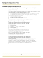
Example 1: Generic configuration file........................................................................................................42
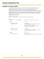
Example 2: Two phase update ..................................................................................................................44
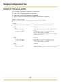
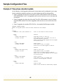
Example 3: Three phase update................................................................................................................45
Example 4: Three phase redundant update ..............................................................................................46
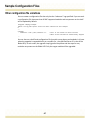
Other configuration file variations ..............................................................................................................47
Appendix B: Updating and Customizing FRU Data....................................................................... 48
Updating FRU data....................................................................................................................................49
Customizing FRU-specific data .................................................................................................................51
Updating FRU data on the ATCA-6006 5U 6-slot shelf .............................................................................53
3
Table of Contents
Appendix C: Updating IPMI FW and FRU Data for an AMC or RTM ............................................. 56
Determining the IPMI firmware version......................................................................................................56
Updating the IPMI firmware .......................................................................................................................57
Reverting to backup firmware....................................................................................................................59
Updating AMC or RTM FRU data ..............................................................................................................59
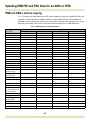
IPMB and IPMB-L address mapping .........................................................................................................60
Appendix D: Updating the BIOS on the CPMs ............................................................................... 62
Prepare the CPMs for the update..............................................................................................................62
For ATCA-4500, ATCA-4550, and ATCA-4555 CPMs .............................................................................64
For ATCA-4616, ATCA-4618, and ATCA-4648 .........................................................................................64
Appendix E: Restoring Older Firmware or Software..................................................................... 66
Appendix F: Troubleshooting ......................................................................................................... 67
Appendix G: Log File Information................................................................................................... 75
4
Preface
About these update instructions
This document describes the rsys_swm utility, which is the upgrade utility provided with the Radisys Software Management Framework (SMF). The rsys_swm utility and the SMF were introduced in the 4.0.0 release as the new tools for making software and firmware updates in the ATCA® system. The rsys_swm utility can perform the update on a single module, a fully‐populated shelf, or simultaneously on multiple shelves–all from the same update host. The updates are performed automatically, which eliminates the need to log on and run update tools on each module. This minimizes user intervention and the possibility of errors. This automatic update process also preserves the current configuration running on the modules and prevents the configuration from being accidently overwritten or corrupted.
Before you begin
This document applies to ATCA software releases 4.1.1 or above. If your system is running a 3.x.x software release, you must upgrade it to the 4.1.1 software release before using these instructions. For instructions on upgrading from 3.x.x to 4.1.1, see the ATCA 3.x to 4.x Firmware and Software Upgrade/Downgrade Instructions. This document assumes the shelf is a Radisys shelf and the Shelf Manager is a Radisys Shelf Manager. If you are updating Radisys modules on a third‐party shelf (i.e., a non‐Radisys shelf), you will need to direct the updates individually at each module on the shelf rather than at a shelf or multiple shelves (see page 18 for more information).
What’s new in this manual
•
•
Added information about the ATCA‐4616, the ATCA‐4618, and ATCA‐4648 Compute Processing Modules (CPMs). Added a new appendix, which describes how to update the BIOS on CPMs (see page 62). Where to get more product information
Please visit the Radisys Web site at www.radisys.com for product information and other resources. Downloads (manuals, release notes, software, etc.) are available at www.radisys.com/downloads.
For additional information about new features, resolved issues, and known limitations in the latest ATCA software release, refer to the ATCA product release notes.
5
Preface
See the following documents for additional firmware and software update information:
• ATCA 3.x to 4.x Firmware and Software Upgrade/Downgrade Instructions
• ATCA Firmware and Software Update Instructions
For information about the PCI Industrial Computer Manufacturers Group (PICMG®) and the AdvancedTCA standard, consult the PICMG Web site at this URL: http://www.picmg.org.
Notational conventions
This manual uses the following conventions
BoldText
A keyword.
ItalicText
File, function, and utility names.
MonoText
Screen text and syntax strings.
BoldMonoText
A command to enter.
ItalicMonoText
Variable parameters.
Brackets [ ]
Command options.
Curly braces { }
A grouped list of parameters. Vertical line |
An “OR” in the syntax. Indicates a choice of parameters. All numbers are decimal unless otherwise stated.
Electrostatic discharge
WARNING! This product contains static‐sensitive components and should be handled with care. Failure to employ adequate anti‐static measures can cause irreparable damage to components.
Electrostatic discharge (ESD) damage can result in partial or complete device failure, performance degradation, or reduced operating life. To avoid ESD damage, the following precautions are strongly recommended. • Keep each module/PCB in its ESD shielding bag until you are ready to install it.
• Before touching a module, attach an ESD wrist strap to your wrist and connect its other end to a known ground. • Handle the module only in an area that has its working surfaces, floor coverings, and chairs connected to a known ground.
• Hold modules only by their edges and mounting hardware. Avoid touching PCB components and connector pins.
For further information on ESD, visit www.esda.org.
6
Chapter
1
Introduction
Supported modules and components
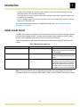
Table 1 lists the ATCA modules and components that can be updated automatically by the Radisys Software Management Framework (SMF). ATCA modules typically have a number of firmware and software components that can be updated. These components are programmed into flash devices or logic devices like FPGAs and CPLDs. Some of the devices act as redundant active‐standby pairs that are updated one‐at‐a‐time. Other devices are single, non‐redundant units. The area on the programmable devices where the software and the firmware components are stored are called banks.
By default, the rsys_swm utility only updates the standby bank of redundant programmable devices. If you want to update both the active and the standby banks on the module, these additional steps are required: • run rsys_swm twice with same config file, or
• repeat the phases in the config file Table 1. ATCA modules and components supported by the SMF
Supported modules
Supported components
ATCA-1200 Quad AMC Carrier
ATCA-2210 Switch and Control Module (SCM)
ATCA-7220 Packet Processing Module (PPM)
ATCA-9100 Media Resource Module (MRM)
Linux
U-Boot image
IPMC FRU data
IPMC application
IPMC boot block
IPMC FPGA
IPMC FRU data
IPMC application
IPMC boot block
IPMC FPGA
CPU BIOS
CPU BIOS boot block
Base NIC (EEPROM)
Fabric NIC (EEPROM)
IPMC FRU data
IPMC application
IPMC boot block
IPMC CC_FPGA
IPMC FPGA
CPU BIOS
CPU BIOS boot block
ATCA-45xx series Compute Processing Modules (CPMs)b
• ATCA-4500 CPM
• ATCA-4550 CPM
• ATCA-4555 CPM
ATCA-46xx series CPMsb
• ATCA-4616 CPM
• ATCA-4618 CPM
• ATCA-4648 CPM
7
Configuration
Number
saved
of banks
automatically?
2
Yesa
2
Yesa
1
Yes
2
N/A
1
N/A
1
N/A
1
Yes
2
N/A
1
N/A
1
N/A
2
Yesc
2
Yesc
1
N/A
1
N/A
1
Yes
2
N/A
1
N/A
1
N/A
1
N/A
2
Yesc
2
Yesc
1
Introduction
a
b
c
For the ATCA‐7220 PPM, the data flow mode selection is not preserved automatically. See the ATCA‐7220 Packet Processing Module Reference.
The CPMs must be running a Radisys supported operating system and any support modules like
the AMCs must be installed.
Use the rsysbflash utility for the ATCA‐45xx series and the ATCA‐46xx series CPMs to save and
restore the configuration. See For a list of components that must be updated manually, see Step 9: Update remaining components on page 39.
Update bundle format
The ATCA 4.2.0 release introduces a new internal format structure and file naming convention for the product update bundles. The new update bundle format supports the SMF update process, and is designed to be easier to use than the previous format.
These are examples of new update and developer bundle names compared with their old names.
Table 2. Bundle format comparison
New bundle name
ATCA-2210-4.2.0.0-wr20-upd.tgz
Old bundle name
ATCA-2210-4.1.2.0-2-firmware.tgz
ATCA-2210-4.2.0.0-wr20-dev.tgz
ATCA-2210-4.1.2.0-2.tgz
ATCA-7220-DPB-4.2.0.0-SDK1.7.2-wr-upd.tgz
ATCA-7220-4.1.2.0_SDK1.7-2-firmware.tgz
Contents
An update bundle contains firmware and
software images, along with tools for automated
or manual updates
A developer bundle contains libraries, software
packages and developer documentation for the
module
In earlier software releases, the image for the
DPBs and sub-FRUs were included in the main
update bundle. With the ATCA 4.2.0 release, the
DPBs and the other sub-FRUs now have their
own update bundles. The tools for the updates
are included in the front module update bundles.
Note: The new bundle format also separates the bundles for front modules and sub‐FRUs. Separate bundles are provided for AMCs, RTMs, DPBs, and the CE3100 COM Express module.
8
1
Introduction
Overview of the Software Management Framework
The sections that follow give a brief description of each SMF component as they pertain to the rsys_swm utility and the update process described in this document. For detailed information on the SMF components, see the ATCA Software Guide. The key components of the SMF are: • System Manager
• Software Management Library (SML)
• Shelf Manager
• Blade HPI server • Firmware upgrade management instruments (FUMIs)
• Firmware tools
• Programmable devices
• Upgrade campaign configuration file
• rsys_swm utility
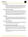
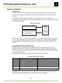
Figure 1 shows the components of the framework and their interactions. Figure 1. Software Management Framework
Configures the upgrade campaign
file and starts the rsys_swm utility.
Executes the update actions from
the update host. Performs version
checking, configuration file
verification, and calls the SML API.
Local operator
Discovers the modules, processes
the phases, identifies and verifies
update bundles, and executes
update actions via HPI FUMI API.
Executes the update actions
using tools and libraries from
the downloaded update bundle.
System Manager
Software Mgr API
SW
Repository
Software Mgmt Lib
HPI FUMI API
Base interface
Base Interface
ACTIVE
Blade
HPI server
Shelf
Manager
Blade
HPI server
STANDBY
Blade
HPI server
Shelf
Manager
Blade
HPI server
Node
modules
Board
Board
software
entities
Board
Board
software
entities
Node modules
Blade
HPI server
Blade
HPI server
Node
modules
Board
Board
software
entities
Board
Board
software
entities
Hub modules
Board
Board
software
entities
Board
Board
software
entities
Node modules
Shelf
Provides access to the Blade HSDs
and forwards the SML requests.
SW Mgt Lib (SML) — Software Management Library
Blade HPI server (Blade HSD) — Upgrade daemon (HPI FUMI API based)
Board software entities — Programmable devices (IPMC, LMP, etc)
9
1
Introduction
System manager
A system manager is a high‐level management application that may manage entities ranging from a single shelf to multiple systems. While the Radisys ATCA software does not currently include a system manager, its shelf management software does provide capabilities and interfaces that a system manager can use to manage ATCA shelves. With SMF, a system manager can perform an upgrade from any update host that has Base Ethernet interface connectivity with the Radisys Shelf Manager and the modules in the shelf. Software Management Library (SML)
The SML is a software library that provides a set of C APIs to perform upgrade actions on specified targets. A C header file is published with SML to export the types, definitions and API prototypes associated with it. Upgrade applications, like the rsys_swm, will include the SML header file and link with the SML to call the associated APIs and execute an upgrade campaign. The APIs automate most of the underlying upgrade process by hiding the upgrade details and presents a easy‐to‐use yet configurable interface to the user. For the update process, RSYS_SMLInfoGet() and RSYS_SmlUpgrade() are the primary SML APIs.
Shelf Manager
The Shelf Manager provides a unified view of all Blade HPI servers to the system manager. The Shelf Manager also provides access to the firmware management upgrade instruments (FUMIs) on the modules and components, which are used for upgrade purposes. See the ATCA Software Guide and the Shelf Management Software Reference for instructions on using the Shelf Manager. Blade HPI servers (Blade HSDs)
The Blade HSDs are API‐based upgrade daemons, which are installed on each Radisys ATCA module. The Shelf Manager communicates over the Base Ethernet interface to the Blade HSD and forwards it SML requests as part of the update process.
Firmware Upgrade Management Instruments (FUMIs)
The FUMI interface is defined by the Service Availability Forum (SAF) in the HPI B.03.02 specification. The Radisys implementation of the FUMI interface is compliant with the HPI B.03.02 specification. The FUMIs provide a control structure and APIs for performing upgrades using different mechanisms. They take the low‐level details of the firmware upgrade operation and abstract and expose them, enabling you to easily build higher level upgrade applications. Each resource and upgrade‐capable software entity is represented by one or more FUMIs. The scope of the FUMI is limited to the upgrade of low‐level hardware components such as OS, BIOS, FPGA, IPMC, and so on. 10
1
Introduction
Firmware tools
Radisys provides firmware tools that interact directly with the hardware to perform software management operations. The firmware tools are Linux‐based and include a set of commands for performing low level operations such as checking for the versions of installed firmware, updating the flash banks, and verifying the images. These tools typically run locally on the local management processor, but some of the tools may be able to perform their operations remotely. For descriptions of the firmware tools and the associated entities, see the ATCA Software Guide.
Programmable devices
The programmable devices are the physical hardware devices that contain the stored programs. Each hardware module has a number of programmable devices modeled as upgradeable software entities. These entities represent the software that exists on non‐
volatile programmable devices, such as Flash and EEPROM, and on logic devices, such as FPGA and CPLD.
Upgrade campaign configuration file
The upgrade campaign configuration file is the file where the parameters for the update are set. The file is used by the rsys_swm utility in determining which modules and components are updated and in what order the updates take place. For details on preparing the file, see Step 6: Define the upgrade campaign configuration file on page 26.
rsys_swm utility
The rsys_swm utility is a fully‐featured utility provided with the source code that you can use to execute an automatic upgrade campaign via the SMF. You can also use the utility for issuing command line interface (CLI) commands that invoke SMF operations at the shelf or module level. This upgrade utility operates as both an HPI and an SMF application using both the HPI Client Library and the SML. The upgrade‐specific operations described in this document are performed using the SML APIs RSYS_SMLInfoGet() and RSYS_SmlUpgrade(). See Step 7: Running the rsys_swm utility for instructions using the rsys_swm utility to perform upgrades.
11
Chapter
2
Performing Updates Using rsys_swm
Procedures for update process
The procedures for updating one or more Radisys shelves is as follows: 1. Plan the update by reading this document and identify which products will be included in the update. See page 7 for a list of the modules and components that can be updated using the rsys_swm utility. 2. Prepare the update host. See page 17.
3. Determine the required IP interfaces. You will need this information when you set up the upgrade campaign configuration file and issue commands using the rsys_swm utility. See page 18.
4. Obtain the release ISO image from Radisys and set up the update repositories. See page 23.
5. Install the software packages on the update host. See page 25.
6. Create a configuration file to identify the Radisys ATCA products to update and the basic update order. See page 26. 7. Run the rsys_swm utility to perform the update. See page 32. 8. Verify the update was successful by checking the report and log files. See page 39. 9. Update any modules and components not supported by the rsys_swm utility manually. See page 39. Step 1: Prepare for the update process
Determine the upgrade campaign host
The upgrade campaign host is the module from which the update process is run. Radisys recommends running the upgrade campaign from either a remote host or a CPM‐based node blade in the system. The upgrade campaign host must be a Linux host with LAN access to the Shelf Manager and the other modules being updated in the system over the Base Ethernet interface. Determine the modules and the components to upgrade
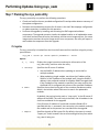
In the upgrade campaign configuration file, you specify which modules and components to include in or to exclude from the upgrade process. You should also determine the order in which to upgrade the modules. For the components, you do not need to specify the update order. Typically, software components on a module are updated in parallel. The order in which the components are activated after the upgrade is based on the order in which the FUMIs are listed by the Blade HSDs. 12
Performing Updates Using rsys_swm
2
If you intend to include Shelf Manager modules like the ATCA‐2210 in the upgrade, some further planning and preparation is required. For redundant Shelf Manager modules, you must first upgrade the standby Shelf Manager module, perform a switchover between the two Shelf Manager modules, and then upgrade the other Shelf Manager module. If you have only one Shelf Manager module (i.e., non‐redundant) in the shelf, you must perform some additional configuration procedures. See page 22 for instructions on upgrading redundant and non‐redundant Shelf Manager modules. Plan the steps for the platform upgrade
You can upgrade the platform using different steps and procedures. For example, you may decide to update only one bank for all the modules and components during the upgrade of a platform. Or you may want to ensure both banks are updated during the upgrade. Below are two possible upgrade scenarios that can be employed to upgrade a platform: Sample platform upgrade: Update one bank
1. Perform the update on all node modules and the ATCA‐2210 acting as the standby Shelf Manager. 2. Perform the switchover procedure on the ATCA‐2210s (see page 22). 3. Perform the update against the ATCA‐2210 acting as the new standby Shelf Manager. To do this, use the command line parameter ‐e when you run the rsys_swm utility (see page 32 for information about the rsys_swm command options). This is the second update pass.
4. Verify the update was successful by checking the report and log files. See page 39.
5. Perform any other verification tasks you typically undertake to confirm software and firmware was successfully loaded and operating correctly. If you decide to update the second bank, you will need to repeat the steps above. Sample platform upgrade: Update both banks
1. Perform the update on all node modules and the ATCA‐2210 acting as the standby Shelf Manager.
2. After the update finishes, repeat Step 1 on the same modules. This updates the second set of banks on the modules. 3. Perform the switchover procedure on the ATCA‐2210s (see page 22). 4. Perform the update against the ATCA‐2210 acting as the new standby Shelf Manager. To do this, use the command line parameter ‐e when you run the rsys_swm utility (see page 32 for information about the rsys_swm command options).
5. After the update finishes, repeat Step 4 on the standby ATCA‐2210. 6. Verify the update was successful by checking the report and log files. See page 39.
7. Perform any other verification tasks you typically undertake to confirm software and firmware was successfully loaded and operating correctly.
13
Performing Updates Using rsys_swm
2
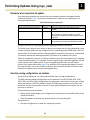
Determine when to perform the update
Your planning should take into account the time needed to perform the update and the downtime involved. Table 3 shows the estimated time it takes for one update pass on a fully‐populated platform. Table 3. Estimated time per update pass
Tasks completed during update pass
Bundle download and image verification
Time
3 minutes
Installation and verification pass
11 minutes
Activation
2 minutes
Affected components
All modules, including Blade HSD restart for bundle
activation.
All LMP, IPMC, BIOS components.
The components are updated in parallel. The process
completes when everything has finished updating on all the
components.
All the Blade HSDs.
This includes the time it takes each Blade HSD to initialize.
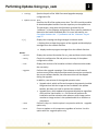
Using this estimate, a single update pass will take approximately 16 minutes. The actual time it takes on your system to perform an update pass will vary depending on the number of phases defined in the configuration file, networking speed, IPMB traffic, and JFFS access speed. The firmware and the software updates are done on live systems, so downtime is limited to reboots that take approximately 5 minutes for all modules in the shelf. Take into consideration that you will need to perform more than one update pass to upgrade a fully‐populated platform. For example, if you are performing a single bank upgrade, you will need to perform two update passes. If you are upgrading both banks, you will need to perform four update passes (see page 13 for examples of the upgrade procedures). You will also need to factor in any time it takes to perform the switchover and the verification steps between the update passes for your total upgrade time. Save the running configurations on modules
Verify all the modules are in a stable state and save their running configurations. The SMF preserves default configurations across updates for the ATCA‐1200, ATCA‐2210, ATCA‐7220, and ATCA‐9100. Configurations are preserved in both banks to retain the existing setup information. Each ATCA software release CD‐ROM image contains a list of files to be preserved, and you can generate a custom list that specifies additional files within the /etc directory to preserve.
File preservation works as follows:
• Before the OS update begins, the configuration is copied from the active flash bank to the standby flash bank.
• After the update is activated, the module reboots to the standby bank.
During boot up:
• the saved configuration is saved to a temporary location,
14
Performing Updates Using rsys_swm
•
•
2
the directories /rsys/onboot.d and /rsys/onboot.data are removed and repopulated by the new release, and
the configuration saved in the temporary location is restored to its proper location.
Files preserved by default
File preservation includes various configurations—Ethernet (Fastpath), module management, shelf management, and others. The system automatically preserves the following files in a default preservation list stored in the /etc/configmgmt.sh file:
/etc/fastpath/fastpath0.cfg
/etc/fastpath/fastpath1.cfg
/etc/fastpath/fastpath.cfg
/etc/snmp/snmpd.conf
/etc/snmp/snmptrapd.conf
/etc/syslog.conf
/etc/ntp.conf
/etc/passwd
/etc/group
/etc/mcli/mclid.cli
/etc/var/lib/snmp/snmpd.conf
/etc/snmp/snmp.conf
/etc/snmp/snmpWatchdog.conf
/etc/snmp/hpiSubagent.conf
/etc/shmgr.conf
/var/lib/shmgr/ShelfFruCopy.bin
/var/lib/shmgr/hcf.tgz
/root/.snmp/snmp.conf
/etc/shmgralarm.conf
/etc/fruinfo.conf
/var/lib/shmgr/atca‐6002.bin
For the ATCA‐7220, the low‐level flash upgrade firmware tool creates a custom preservation list at /etc/rsys‐user‐file‐list.cfg during the update process if the file does not already exist. The rsys‐swm utility adds the following ATCA‐7220 configuration files to that custom preservation list:
/etc/octeon.conf
/etc/fpga/ppm20fpga.conf
All files in /etc/octeon
See Create a custom preservation list on page 16 for more information about using the /etc/rsys‐user‐file‐list.cfg file.
15
Performing Updates Using rsys_swm
2
Create a custom preservation list
You may want to preserve other files that are not preserved automatically. For example, if you have an ATCA‐2210 SCM running a DHCP server, you may want to preserve its DHCP configuration files.
To preserve additional configuration files, add them to the /etc/rsys‐user‐file‐list.cfg file. If this file is not available on your system, you may need to create it.
When adding the configuration file names to the rsys‐user‐file‐list.cfg file, make sure each file name is listed on a separate line, and that the file entry includes the path location. For example, these commands add the xxx.cfg and yyy.cfg files to the custom preservation list:
echo “/etc/xxx.cfg” > /etc/rsys‐user‐file‐list.cfg
echo “/etc/yyy.cfg” >> /etc/rsys‐user‐file‐list.cfg
Save the file when the additions are complete.
Preserve other files and configurations manually
Most files outside of /etc cannot be preserved by the tools. Consider whether to manually save the files you have created outside of /etc, such as the DHCP leases file.
To preserve configuration files outside the /etc directory, add them to the /rsys/onboot.data/overlay directory and then include a reference to them in the /etc/rsys‐user‐file‐list.cfg file.
An alternative method for manually saving files is to copy the files to a remote server (using FTP, SFTP, TFTP, etc.) before running the update. Copy them back to the module after the update is complete. Use FTP or SFTP to achieve the best performance and reduce the update time.
For the ATCA‐7220 PPM, data flow mode selection is not preserved automatically. For details on mode configuration, refer to the ATCA‐7220 Packet Processing Module Reference.
Check the version information on the update targets
Verify all update targets are at release 4.0.0 or higher. CLI commands are available to identify the software, firmware, and hardware versions in use. To identify the software and firmware versions from the CLI, enter:
show version
To identify the hardware revision and information about the module components, enter:
show hardware
In addition, the versions of all installed packages are listed in the /etc/versions file.
16
Performing Updates Using rsys_swm
2
Step 2: Prepare the update host
The update host must be a Linux host with LAN access to the modules in the shelf. All update targets must be accessible via the Base Ethernet interface from the update host running rsys_swm. The update repository must be local to the update host. Currently, the rsys_swm utility only supports “file://” type uniform resource identifiers (URIs) for its repository location parameter (“releaseuri” tag in the configuration file).
You can run the update campaign from either a remote host or a node module installed in the system (e.g., ATCA‐45xx series CPMs, ATCA‐46xx series CPMs, or COM Express modules). All operating systems supported by Radisys also support the SMF, and thus are capable of running the rsys_swm update process. While it’s possible for LMP‐based modules (e.g., ATCA‐1200, ATCA‐2210, ATCA‐7220, or ATCA‐9100) to run the update campaign, Radisys does not recommend doing so. This is because the LMP‐based modules do not have the flash or the RAM space required to mount the CD ISO image locally. Determine the file transfer method
Determine which file transfer method will be used for downloading the software bundles from the remote repository on the update host to the modules on the shelf. Currently, TFTP and FTP are the only transfer protocols supported by the SMF update process. Verify the update host is running the appropriate file transfer daemon for your chosen file transfer method. 17
Performing Updates Using rsys_swm
2
Step 3: Determine and configure the required IP interfaces
Updates to multiple modules
When updating an entire shelf or multiple modules within a shelf, you will need to provide the Shelf Manager server’s (ShMS) IP address to the rsys_swm utility for the update server’s IP address.
Updates to a single module
When updating a single module, you either can provide the specific module’s IP address or the ShMS IP address, with the module’s entity as an additional parameter to the rsys_swm utility. The ShMS IP address is preferred for Radisys ShMS‐managed shelves. If you provide the ShMS IP address, you may need to configure the Blade HSD on each module so it is accessible to the update host over an IP interface. See Configure an IP interface for the Blade HSD on page 19 for instructions on configuring a module’s Blade HSD. Updates to modules on a third-party shelf
When updating modules on a third‐party shelf (i.e., non‐Radisys shelves), the updates must be directed individually at each module on the shelf. To do so, provide each module’s IP address to the rsys_swm utility. In addition, the Blade HSD on each module must be accessible to the update host over a configured IP interface. See Configure an IP interface for the Blade HSD on this page for instructions on configuring a module’s Blade HSD. Updates to CPMs
When updating CPM modules, you must configure the module’s Blade HSD so it is accessible to the update host over an IP Interface. See Configure an IP interface for the Blade HSD on this page for instructions on configuring a module’s Blade HSD. Verify the Blade HSD is registered
Before running the upgrade, verify the Blade HSDs are registered with the ShMS. To do this, run the rsys_swm utility from the Linux update host using the “info” action option. For example: rsys_swm ‐i <ShMS IP Addr> ‐‐info
This command will print out the version information from all the FRUs in the shelf and also create a report. You can then verify that all FRUs present in the shelf reported version data. If version data is reported, it confirms the Blade HSD of that FRU is registered with the Shelf Manager. For LMP‐based modules, the Blade HSD is automatically registered with the Shelf Manager. For CPMs, the Blade HSD is registered when the CPMs are activated for service in the shelf. 18
Performing Updates Using rsys_swm
2
If a particular FRU is missing from the version report, then its Blade HSD is not registered with the Shelf Manager and you will need to edit its configuration file and set up IP interfaces. See Configure an IP interface for the Blade HSD below for information.
Configure an IP interface for the Blade HSD
You must configure an IP interface for the Blade HSD when performing the following types of updates: • Updating modules on a third‐party shelf (i.e., non‐Radisys shelf)
• Updating a CPM
The Blade HSD configuration file “rsyshsd.conf” is located on each module at this location: /etc/rsyshsd.conf The different Radisys module types have unique rsyshsd.conf files. However, the file do share three common parameters for configuring the IP interface:
• RSYSHSD_BASE_INTERFACE: This parameter names an interface on the module that the Blade HSD uses to attach a RMCP interface. This enables RMCP‐base remote HPI access to the Blade HSD over the interface. The advantage of providing an interface name rather than an IP address is that it enables Blade HSD to support dynamically allocated addresses and situations where the IP address changes during operation. Blade HSD tracks to the interface (e.g., eth0) and is able to detect any ip address changes and automatically re‐
bind to that interface with its updated ip address.
•
•
Radisys recommends using a port associated with the Base Ethernet or a bonded interface for this parameter. RSYSHSD_FABRIC_INTERFACE: This parameter names an additional interface on the module that the Blade HSD uses to attach a second RMCP interface. As the parameter name indicates, Radisys recommends using a port associated with the Fabric Ethernet for this interface. However, this is not a requirement, and a non‐fabric interface can also be used for this parameter. For third party shelf upgrades, or upgrades directed at individual modules rather than through the Shelf Manager, this parameter can be configured with an interface reachable from the update host. For example, the management port eth0 or the Base Ethernet interface eth1 on LMP‐based modules.
RSYSHSD_SHMS_INTERFACE: This parameter specifies whether the interface named for the RSYSHSD_BASE_INTERFACE parameter or the interface named for the RSYSHSD_FABRIC_INTERFACE parameter is the preferred interface for the Blade HSD to communicate with the Shelf Manager. The IP address of the chosen interface is communicated with the Shelf Manager, and then used in establishing HPI communication with the Blade HSD. Radisys recommends using the same interface as the interface named for the RSYSHSD_BASE_INTERFACE parameter.
19
Performing Updates Using rsys_swm
Sample rsyshsd.conf file
The three IP interface parameters appear near the bottom of the configuration file. An example of a configuration file for a CPM module is shown below. #!/bin/sh
########################################################################
## RadiSys Confidential ##
## RadiSys Promentum(TM) ATCA Blade HPI Management ##
## (C) Copyright RadiSys Corporation 2004‐2005. All Rights Reserved. ##
## ##
## The source code for this program is not published or otherwise ##
## divested of its trade secrets, irrespective of what has been ##
## deposited with the U.S. Copyright Office. ##
########################################################################
#
# hsd.conf ‐ This file contains the configuration settings that override the default # settings for the Modular HPI server running on the Radisys ATCA Blades. # Edit this file to override default configuration setting in shmgr.defs.
# e.g. # Default Blade HSD command line arguements in shmgr.defs:
# RSYSHSD_CMDLINE_ARGS="‐‐verbosity 5 ‐‐maxlog 8000000"
# Desired override command line args: # "‐‐verbosity 7 ‐‐maxlog 10000000"
#
# You must specify a '‐‐maxlog' value that is less than half of the amount
# of free disk space available.
# # Add the following to this file to override defaults:
# RSYSHSD_CMDLINE_ARGS="‐‐verbosity 7 ‐‐maxlog 16000000"
#
# Default network interfaces for the blade HPI server will need
# to be correctly ste up to match user configuration. Please
# update the BASE and FABRIC INTERFACE definitions accordingly.
# When CPM is configured in enhanced mode shelf manager BASE
# must be set to an alias of eth0.
RSYSHSD_BASE_INTERFACE=eth0
RSYSHSD_FABRIC_INTERFACE=eth1
RSYSHSD_SHMS_INTERFACE=eth0
HSD_DRDR_CONF=fumi
20
2
Performing Updates Using rsys_swm
2
CPM-specific recommendations
On CPM modules, the interfaces are set to the following by default:
• RSYSHSD_BASE_INTERFACE: eth0
• RSYSHSD_FABRIC_INTERFACE: eth1 • RSYSHSD_SHMS_INTERFACE: eth0 If the CPMs in your system use bonded interfaces to communicate with the Shelf Manager over the Base Ethernet, you will need to edit the default parameters and name the bonded interfaces. for the RSYSHSD_BASE_INTERFACE and the RSYSHSD_SHMS_INTERFACE parameters. The RSYSHSD_FABRIC_INTERFACE is optional, but if a second RMCP interface is desired, a valid interface with connectivity must be assigned. For example, this parameter could be set to the front panel management interface eth0 for direct access to the Blade HSD from remote management hosts: • RSYSHSD_BASE_INTERFACE=bond0
• RSYSHSD_FABRIC_INTERFACE=eth1
• RSYSHSD_SHMS_INTERFACE=bond0
21
Performing Updates Using rsys_swm
2
Updates to the Shelf Manager modules
If you execute the upgrade using the Shelf Manager’s IP address against a shelf with redundant Shelf Manager modules (e.g., the ATCA‐2210s), the active Shelf Manager module will be automatically skipped. Only the standby Shelf Manger module will be updated. To update the active Shelf Manager module, you can perform a switchover on the Shelf Manager modules and change their active/standby status. After the switchover, run the update again against the new standby Shelf Manager module. Perform a switchover
You can use either of the methods described below to change the Shelf Manager’s status and role from standby to active.
From the CLI of the Shelf Manager, enter:
platform‐mgmt shelf‐mgmt configure switchover
From the Linux root of the Shelf Manager, enter: shmgr switchover
Updating a non-redundant Shelf Manager module
If the Shelf Manager is non‐redundant (for example, has only one ATCA‐2210 acting as the Shelf Manager), you will need to run the update against the Blade HSD on the ATCA‐2210. Important! When updating an ATCA‐2210 acting as the non‐redundant Shelf Manager, be aware that the shelf will be unmanaged as the ATCA‐2210 reboots following the activation stage. The IP address of the ATCA‐2210 associated with the Blade HSD is: dtl0:hsd
This IP address should be provided to rsys_swm as the host ip address.
22
Performing Updates Using rsys_swm
2
Step 4: Obtain the release ISO image from Radisys
An ATCA Software image is available at www.radisys.com/downloads. Browse to the downloads page for the AdvancedTCA platform system (for example, the SYS‐6010 platform). From the Software downloads section, download the .zip file (or files) that contain the ISO image. Once the ISO image has been extracted, perform the procedures described in the following sections. Download and mount the ISO image on to the update host
You must download and mount the ISO image on to the update host. 1. Download the ISO image to the update host. For instructions downloading (or copying) files from a remote host or a network location to a module, see the ATCA Software Guide. 2. On the update host, create a folder to serve as the mount location. Note that you may need root privileges to create this folder. For example, enter:
mkdir ‐p /mnt/release
3. Mount the image using the following syntax:
mount ‐o loop <iso image> <mount folder>
For example: mount ‐o loop Promentum‐Software‐4.1.1‐<iso version #>.iso /mnt/release
The mounted location becomes the update repository. Note that this update repository must be accessible locally from the update host running the rsys_swm utility, as currently only “file://” URIs are supported for the “releaseuri” tag, which specifies the URI of the update repository on the update host, in the campaign configuration file. Set up a remote repository
If you select a LMP‐based module (like the ATCA‐2210), or one of the node modules like an ATCA‐4500 CPM, as the update host, you may need to mount the ISO image on a remote machine due to space limitations. For this type of set up, you will also need to mount a network file system (NFS) on the node module to access the ISO image on the remote machine. 1. Mount the ISO image on a remote host with IP access to the Shelf Manager (see page 23 for instructions on mounting an ISO). The remote host can be the system management host or even a COM‐Express. For these instructions, the image mounted on the remote host is located in this folder: /mnt/release
2. Export the /mnt/release folder, so it can be NFS mounted from the remote host to other machines. You will need root permissions to perform this export. exportfs ‐o no_root_squash *:/mnt/release
3. Enter the following command to verify the /mnt/release folder is listed.
exportfs ‐v
23
Performing Updates Using rsys_swm
2
If the export was successful, you will see the folder listed. 4. Log on to the module (for example, an ATCA‐2210) that will run the rsys_swm utility and create a directory with the same path: mkdir /mnt/release
The repository path must be the same on both the remote host and the module.
5. Mount repository from the remote host using nfs:
mount ‐t nfs <IP Address‐remote host machine>:/mnt/release /mnt/release
You may receive some warning messages at this point. You can ignore these messages and proceed. The repository is now nfs‐mounted on the ATCA and the campaign can be run from the ATCA‐2210 using the same configuration file as if the campaign were being run from the remote host machine.
Note: The LMP‐based modules do not support an FTP server. If you need to use FTP as the protocol for downloading bundles, be sure to specify the IP address of the remote host used to nfs‐mount the repository for the ‐s parameter when you run the rsys_swm utility. The ‐s parameter specifies the repository host server. See page 32 for more information. Create a customized repository
If not all of the module folders on the ISO image CD are applicable to your system’s configuration (i.e., some of the module folders are for products you do not use), you can create a partial customized repository. 1. Create a repository storage location on the update host. 2. Copy the specific module folders you need to a repository storage location on the update host. 3. Copy the bundle map file, bundlemap.txt, from the root directory of the ISO image CD to the root directory of the repository you created on the update host. SML uses this bundle map file to identify the correct update bundle for each module in the system.
24
Performing Updates Using rsys_swm
2
Step 5: Install the software packages
Locate the following packages and install them on the update host in the order shown here: 1. The HPI client library package: libhcl‐1.6.4 (or higher)
2. The YAML library software packages: libyaml‐0.1.3 3. The RPC support package: rsys‐rpc‐support‐1.0.53‐1 (or higher)
4. The SML package: libsml‐0.1.13 (or higher)
RPMs for these packages are provided with the development bundles in the ISO image, and come with both source code and binary images for all the Radisys‐supported operating systems.
If you want to build from the source code use the file with the extension “tar.gz.” Refer to standard Linux documentation for directions on building from source code.
If you want to install the pre‐built binary images for Radisys supported operating systems, use the RPMs. For example, the SML package for an ATCA‐4500 CPM running the 64 bit version of RedHat Linux would be found at this location: ATCA‐4500‐4.x.x‐1‐rh5_64/development/libsml‐0.1.13 (or higher)
You can install individual runtime packages directly onto the update host using the Linux rpm utility. A target root path and additional command‐line options must be used to install a package onto a development host when it is meant to run on a separate target system (such as a module).
To install a package:
rpm ‐i <path><pkg_name>
To list the installed packages:
rpm ‐qa
25
2
Performing Updates Using rsys_swm
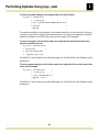
Step 6: Define the upgrade campaign configuration file
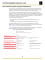
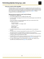
Before you can run the update process, you must create and define an upgrade campaign configuration file. This configuration file is used by the rsys_swm utility in determining which modules and components are updated and in what order the updates take place. You can generate an upgrade configuration from the sample text file “config.cfg” that is available in /usr/share/rsys_swm/ folder. The file is correctly formatted and contains most of the tags, so edit it as needed, and save the file with a name that will make it easily identifiable as the upgrade campaign file. For example, “upgrade‐campaign.yml” or “upgrade‐config.yml.” The file can have a .yml extension or a .cfg extension. The file includes the following sections: • An introductory section, which describes the different tags (or parameters) in the document.
• A campaign section, where you enter the specific parameters for the update. The upgrade configuration file can be set up to run the update process on modules sequentially or in parallel. When modules are updated in parallel, they are in the same phase. See phase tag on page 28 for more information about phases.
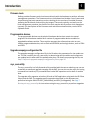
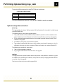
Figure 2 below shows the details of the campaign specification section. For an example of an upgrade configuration file that includes the tag descriptions, see page 41.
Figure 2. Upgrade configuration file: campaign section example
# Upgrade campaign example
#
# This file is used for specifying the upgrade campaign.
#
--campaign:
Update repository location
- releaseuri: file:///mnt/release-4.0.1
Components skipped on all modules
- exclude: system-boot, boot-block, legacy-fpga # skip UBoot, BIOS boot-block, &
legacy FPGAs on all modules
- phase:
# Phase 0
- step:
- module: board.8
# upgrade the board in slot 8
Module in slot 8 and ATCA-4500s in slots 2
- exclude: fru-data
# skip IPMI fru data
& 5 are updated in parallel in the first phase
- step:
ATCA-4500s are expected to run the Wind River
- module: ATCA-4500.[2,5]
# upgrade ATCA-4500s in slots 2 and 5
Ver 2, 32 bit operating system.
- os: wr2_32
# Use the update bundle for WR2 32 bit OS
Components skipped on the ATCA-4500s
In second phase, all ATCA-1200s are updated
- exclude: ipmc-, fru-data
- phase:
- step:
- module: ATCA-1200
...
26
# skip ipmc components and fru data
# Phase 1
# Upgrade all ATCA-1200s in the shelf
2
Performing Updates Using rsys_swm
Required configuration
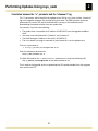
releaseuri tag
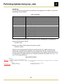
This tag specifies the URI of the update repository on the update host. This is the mount location of the release CD ISO image or the root of the update repository where the ISO is mounted. The software bundles must be accessible from the update targets (i.e., modules and components) using the URI specified for the update repository. The IP connections are shown in the following diagram:
Figure 3. IP connections
Host running rsys_swm
Target
module
tftp/ftp/www server
containing update bundle
IP address
(example: 10.10.10.1)
IP address
(example:
10.10.10.2)
Currently only “file://” URIs are supported and this is the reason why the repository must be set up or mounted locally on the update host. This parameter is required because the SML uses the bundle map file located in the repository to identify the software bundles for the modules. os tag (CPMs and ATCA-7220 PPMs only)
Various bundles are available for some module, based on the operating system or the software development kit (SDK). The OS tag is where you specify the appropriate bundle. Currently, this tag is only required for the ATCA‐45xx series CPMs, the ATCA‐46xx series CPMs, and the ATCA‐7220 PPMs. The possible operating systems supported for the CPMs are listed below:
Table 4. Operating systems for the CPMs
Parameter
mv5_64
mv6_64
wr2_32
wr2_64
wr4_64
rh5_64
rh6_64
Description
Monta Vista, version 5, 64 bit
Monta Vista, version 6, 64 bit
Wind River, version 2, 32 bit
Wind River, version 2, 64 bit
Wind River, version 4, 64 bit
Red Hat, version 5, 64 bit
Red Hat, version 6, 64 bit
CPM product support
ATCA-45xx series
ATCA-46xx series
ATCA-45xx series
ATCA-45xx series
ATCA-45xx series, ATCA-46xx series
ATCA-45xx series
ATCA-46xx series
Important! An operating system must be specified for the CPMs. No bundle will download and the upgrade process will fail if an operating system is not specified. 27
Performing Updates Using rsys_swm
2
The possible SDKs supported for the ATCA‐7220s are listed below: Table 5. SDKs for the ATCA-7220s
Parameter
SDK1.7
SDK1.9
SDK 2.1
Description
Software development kit, version 1.7
Software development kit, version 1.9
Software development kit, version 2.1
If no SDK is specified for the ATCA‐7220, the SDK1.7 bundle is used for the update. Optional configuration and actions
phase tag
This tag specifies the phases. Without phases SML will update all the modules in shelf, except the active ShMS host.
The following occurs during each upgrade phase:
• The update bundles are identified and downloaded in parallel on all the modules in the group. Update tools and utilities in the bundle are installed for use during the upgrade. • All non‐excluded programmable devices are installed in parallel, where possible, on all modules in the group.
• All modules in the group are activated in parallel. • The updated programmable devices on each module are activated in sequence, which is defined by the order that their associated FUMIs are listed by the module’s Blade HSD. The following is specified for each phase:
• The list of the modules to upgrade
• Any programmable devices to exclude from the upgrade
step tag
This tag specifies the parallel updates within each phase. A step defines a module or a group of modules of a specified type of identity. A step can also specify the programmable devices to exclude from the upgrade.
Each step can have only one module tag specified.
28
Performing Updates Using rsys_swm
2
module tag
This tag identifies modules to be updated. See Supported modules and components on page 7 for the list of the modules supported by this configuration file.
The modules are identified in the configuration file using this format:
‐module: <FRU type>.<instance>
Use either a type or a name tag for the FRU type parameter. Currently, the only allowed type is “board,” but future versions of rsys_swm may support other types. The “board” type maps to the front modules. Allowed name tags are in the ATCA‐XXXX format. For example: ATCA‐7200
For the instance parameter, the following instance types are allowed: • An absolute number.
• A wildcard ‐ ' ' or no '.' after type or name.
• The slot range. For example: [1‐4].
• A list of the applicable slots in the shelf. For example: [5,6,9,10].
To specify the front modules in slots 1 through 5 of the shelf:
‐module: board.[1‐5] To specify all the front modules installed in the shelf:
‐module: board
To specify all the ATCA‐7220 modules installed in the shelf:
‐module: ATCA‐7220
To specify the ATCA‐4500 modules installed in slots 13 and 14 of the shelf: ‐module: ATCA‐4500.[13,14]
In situations where a specified module is not found in the shelf, the rsys_swm utility will ignore it and proceed with the remainder of the campaign. The resulting upgrade report will indicate the specified slot was not updated because of a module name or FRU type/instance mismatch. For example, if a module tag is specified: ATCA‐7220.[1,2,5,7] and there is no ATCA‐7220 in slot 7 then the campaign will continue on and update the ATCA‐7220s in slots 1,2 and 5. Any other type of module installed in slot 7 will be skipped. This ensures that only boards of the specified modules are updated and protects against unspecified shelf configuration changes. 29
Performing Updates Using rsys_swm
2
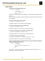
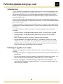
exclude tag
This tag specifies the components to exclude from the upgrade for all modules. The possible exclude tags are listed below: Table 6. Exclude tags
Tag
system-os
system-boot
bios
ipmcipmc-app
ipmc-boot
ipmc-fpga
fru-data
boot-block
legacy-fpga
commux-cpld
base-nic
fabric-nic
front-nic
Description
LMP, Linux kernel filesystem.
U-Boot.
BIOS.
IPMC for the application block, the boot block, and the FPGA.
IPMC for the application block only.
IPMC for the boot block only.
IPMC for the FPGA only.
FRU data.
BIOS boot block.
Fawkes FPGA on the CPMs.
CPLD on an ATCA-7220 PPM.
Base EEPROM on all CPMs.
Fabric EEPROM on all CPMs.
Front EEPROM on all CPMs.
You can provide partial tag names in the exclusion list for related groups. For example, to exclude all IPMI entities, specify: ‐exclude: ipmc‐
Similarly, to exclude all LMP‐related components, specify: ‐exclude: system‐
Exclusion lists can be specified for global or module entities. For a global exclusion, the exclude tag is specified above the phases in the configuration file. For a module‐specific exclusion the exclude tag is specified in the phases with a step. Module‐specific exclusion lists are appended to the global exclusion list, if specified. Duplicates are ignored. See Figure 4 on page 30 for sample exclusions.
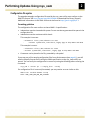
Figure 4. Exclude examples
campaign:
- releaseuri: file:///mnt/release-4.0.1
Global
- exclude: system-boot, boot-block, legacy-fpga
- phase:
- step:
- module: board.8
Module-specific
- exclude: fru-data
# skip U-Boot, BIOS boot-block, & legacy FPGAs on all modules
# Phase 0
# upgrade the board in slot 8
# skip IPMI fru data
30
Performing Updates Using rsys_swm
2
Configuration file syntax
The upgrade campaign configuration file used by the rsys_swm utility must conform to the YAML file format. See http://pyyaml.org/wiki/LibYAML to download the library (libyaml). Additional information on the YAML format can be found at http://yaml.org/spec/1.1. Formatting guidelines
The configuration file must conform to these YAML 1.1 specifications:
• Indentations must be inserted with spaces. Do not use tabs to generate white space in the configuration file. • Indentation must be consistent within levels. This example is incorrect:
‐ releaseuri: file:///mnt/release‐4.x.x‐EI2
‐ exclude: system‐boot, boot‐block, legacy‐fpga # skip UBoot and BIOS
This example is correct: ‐ releaseuri: file:///mnt/release‐4.x.x‐EI2
‐ exclude: system‐boot, boot‐block, legacy‐fpga # skip UBoot and BIOS
•
Comments can be placed in the file, preceded by a # symbol
If you copy any of the sample configuration files from this document (see page 41), you will need to properly format the file using the YAML specification so the rsys_swm utility can parse it. You can verify the configuration is correct by issuing the following before running the command:
rsys_swm ‐i <server ip> ‐c <config file> ‐‐verify If a configuration file is incorrectly formatted, you may receive an error similar to this:
YAML Error: Invalid element in map
Code: YAML_LOAD_ERR_BAD_MAP_ELEMENT
31
Performing Updates Using rsys_swm
2
Step 7: Running the rsys_swm utility
The rsys_swm utility can perform the following operations: • Checks and verifies the user provided configuration file and provides advance summary of the update configuration. • Retrieves active and backup versions for all assets in the shelf. No campaign configuration or update repository is needed for this operation. • Performs the upgrade by installing and activating the SMF‐supported software components. The upgrade operation installs the update bundles on all updateable assets in the shelf and retrieves the active, the backup, and the source image versions. If a source image version matches the active image version on a component, the utility will report it and exclude the component from the upgrade. CLI syntax
The rsys_swm utility is invoked from the linux shell command line interface using this primary syntax format: rsys_swm ‐i <server‐ip> <action specific parameters> ‐‐action Options:
‐h, ‐?, ‐‐help
Displays the usage instructions and version information of the rsys_swm utility, and then exits the utility.
‐i <serverip>
Specifies the HPI server IP address. •
‐e <Root> Use the ShMS’s IP address when updating an entire shelf or multiple modules.
• When updating a single module, use either the IP address of the ShMS or of the IP address of the module itself. Using the ShMS IP address is the preferred method for a Radisys ShMS‐managed shelf. If the IP address of the module is specified, you must confirm that the Blade HSD is configured with access to the specified IP address.
Specifies the top level entity path of the container hardware module, which is the location where SML starts its search for updateable modules.
By default, the top level entity path or “root entity” is the HPI server IP address of the ShMS. The root entity is the Shelf, and all modules in the shelf are considered for the upgrade.
If an HPI server IP address of a particular module’s Blade HSD is specified with the ‐i parameter, the root entity is the module, and only the module and its components are considered for the upgrade.
‐r <Report> Specifies the path of SML report file. By default, the report is named “report.yml” and is located in the current working directory from which rsys_swm is being run. 32
Performing Updates Using rsys_swm
‐c <config>
2
Species the path of the YAML formatted upgrade campaign configuration file.
‐s <Update Server URI>
Specifies the URI of the update server host. The URI is used by modules to download update bundles from the repository on the update host. This parameter, along with the information provided for the “releaseuri” in the campaign configuration file are used by modules to determine the bundle download path. For more information, see Correlation between the “‐s” parameter and the “releaseuri” tag on page 37.
‐v[v]
Displays the campaign tracking messages in verbose mode:
‐v displays dots to show the progress of the upgrade and also displays messages from the callback function.
‐vv displays verbose progress messages from the callback function. Actions:
‐‐version Displays the version information for rsys_swm and then exits the utility.
‐‐verify Checks the configuration file and prints a summary of the update configuration results.
‐‐info Displays the versions of all modules and their software entities under the root entity.
‐‐upgrade Performs the upgrade campaign. If the software or the firmware versions on any of the software entities match the versions contained in the current software bundle, the software entities will be skipped during the upgrade. In addition, two variants of the upgrade operation exist: •
‐‐check
‐‐force
Upgrade check, which verifies and compares the presently installed image versions with the image versions included in the update bundles, but does not install or activate the software.
• Upgrade force, which updates all programmable devices regardless of the version check results. I.e., this variant will perform the installation and the activation even when an active image version matches an image version in the update bundle for a module or a component.
Performs a dry‐run. Use this option in conjunction with the ‐‐upgrade option only.
Forces an update on all components regardless of version. Use this option with the ‐‐upgrade option only.
33
Performing Updates Using rsys_swm
2
Using rsys_swm to perform upgrades
The default behavior of the rsys_swm utility is to upgrade all entities under the default root entity path when no phases are specified in the configuration file. However, additional control over the order and phasing of the upgrades can be controlled through the upgrade campaign file. For information on configuring an upgrade campaign file, see page 26. Sample configuration files are also provided on page 41.
Before performing an upgrade on a shelf, verify the following:
•
•
•
All modules are in a stable state.
The running configurations for all modules have been saved. The Radisys ShMS is managing the shelf and that all the update targets are accessible from the active ShMS. To verify the ShMS is running and managing the shelf, you can enter either of the following commands on an ATCA‐2210. From the Linux root: root@ATCA‐2210@43‐1‐7:~# shmgr status
From the CLI, enter: platform‐mgmt
show chassis status
•
•
•
•
•
The update repository has been set up and is available locally on the update host machine. The update host is running the appropriate file transfer servers (TFTP or FTP daemons) so the update bundles can be downloaded to the modules from the repository. All update targets are reachable over the Base Ethernet interface from the host machine running rsys_swm during and after their update.
The Blade HSDs for all the modules are registered with the ShMS, if you are performing a shelf‐level upgrade with multiple blades and phases. See page 18 for information. For single module upgrades, verify the Blade HSD is running on the module and it is accessible over the Base Ethernet. See page 18 for information.
34
Performing Updates Using rsys_swm
2
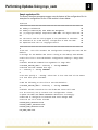
Usage examples
To perform a dry run of the upgrade campaign, enter:
rsys_swm ‐i 192.168.16.17 \
‐c ./config.cfg \
‐s tftp://10.100.110.45 \
‐‐upgrade ‐‐check
192.168.6.17 is the IP address of the Shelf Manager and 10.100.110.45 is the IP address of the update host.
The dry run checks the integrity of images and displays the modules and software entities that will be upgraded.
To retrieve the versions of all the entities in the shelf:
rsys_swm ‐i 192.168.16.17 ‐‐info
The specified IP address is the IP address of the Shelf Manager. To retrieve the versions of all the entities on a specific module:
rsys_swm ‐i 10.100.18.22 ‐‐info
The specified IP address is the IP address of the module’s Blade HSD.
To retrieve the version information of all the entities for the module in slot 2:
rsys_swm ‐i 10.100.18.22 ‐e board.2 ‐‐info
The specified IP address is the IP address of the module’s Blade HSD.
To verify the contents of an upgrade campaign file:
rsys_swm ‐i 192.168.16.17 ‐c ./upgrade‐campaign.yml ‐‐verify
The specified IP address is the IP address of the Shelf Manager. To perform an upgrade campaign on all the entities under the root entity of an HPI domain and display the
campaign tracking messages in verbose mode:
rsys_swm ‐i 10.100.18.22 \
‐c ./config.cfg \
‐s ftp://johndoe:[email protected] \
‐‐upgrade ‐vv For parameter ‐i, the specified IP address is IP address of the ShMS. For parameter ‐s, the specified URI is the URI of the update host. 35
Performing Updates Using rsys_swm
2
To perform an upgrade campaign on the software entities on a specific module:
rsys_swm ‐i 10.100.18.22 \
‐c ./config.cfg \
‐s ftp://johndoe:[email protected] \
‐e board.8 \
‐‐upgrade
The module specified for this example is the module installed in slot 8 of the shelf. Using the ‐
e option can significantly speed up the update process, as it directs the upgrade at a specific board (for example, at the ATCA‐2210 acting as the standby Shelf Manager). To perform an upgrade on all the entities named in the configuration file and output the results of the
upgrade to a specified report file:
rsys_swm ‐i 192.168.16.17 \
‐c config.yaml \
‐s tftp://10.100.110.45 \
‐r ./upgrade_report.yml 192.168.6.17 is the IP address of the Shelf Manager and 10.100.110.45 is the IP address of the update host.
To force an upgrade campaign on all the entities named in the configuration file even if the version of the
entities have not changed:
rsys_swm ‐i 192.168.16.17 \
‐c ./config.cfg \
‐s tftp://10.100.110.45 \
‐‐upgrade ‐‐force 192.168.6.17 is the IP address of the Shelf Manager and 10.100.110.45 is the IP address of the update host.
36
Performing Updates Using rsys_swm
2
Correlation between the “-s” parameter and the “releaseuri” tag
The “s” parameter, which identifies the update server URI for rsys_swm, and the “releaseuri” tag in the upgrade campaign file correlate with each other. The SML combines these two parameters to create a URI, which the Blade HSDs running on the modules use for downloading the update bundles from the update host.
For example, if you have the following:
• The update host is accessible via IP address 10.100.19.15 from the upgrade candidate shelf.
• Your user name and password is “johndoe” and “password.”
• The Shelf Manager IP address in the shelf is 10.100.19.17.
• The 4.x.x release iso image is mounted at /mnt/release‐4.x.x on the update host.
Then the ‐s parameter is: ‐s as ftp://johndoe:[email protected]
Enter the releaseuri parameter as:
file:///mnt/release‐4.x.x.
The SML will combine the ‐s and releaseuri parameters to create the following URI: ftp://[email protected]//mnt/release‐4.x.x This is used by the upgrade servers to download the FRU update bundles from the upgrade host machine via FTP.
37
Performing Updates Using rsys_swm
2
Callback function
The rsys_swm utility implements a sample callback function in its code that adheres to the callback API prototype published in the SML header file rsys_swm_api.h and defined in the API documentation (rsys_sml_api_reference.doc) generated by the SML library code. By default, the sample callback only tracks the upgrade campaign’s progress and displays it on screen in verbose mode. You can edit the sample callback code and construct more complex callbacks that perform operations like Shelf Manager and application switchovers, or commission updated modules after module activation. The rsys_swm utility can either ignore the callback events or execute custom operations like performing a switchover between phases or commissioning updated modules after module activation.
The callback function is called at these points during the upgrade for the callback API prototype: • Discovery stage 1: An upgrade‐capable module is found. The entity path is provided. • Discovery stage 2: An upgrade‐capable software entity is found. The entity path is provided. • Phase: A phase is started or completed. The phase index is provided. • Upgrade operation 1: An upgrade operation (e.g., installation, activation, etc.) starts, completes, or fails on a module. The entity path and the operation type are provided. • Upgrade operation 2: The upgrade operation starts, completes, or fails on a software entity. The entity path and operation type are provided.
Performing the upgrade on one module
To perform the upgrade on a single module rather than an entire shelf, you can do any the following:
• Run rsys_swm against a campaign configuration file that has only one module listed in its specification. • Run rsys_swm against a shelf level campaign configuration file and use the option ‐i to specify the target module’s Blade HSD IP address as the HPI server IP address. • Run rsys_swm against a shelf level campaign configuration file and use option ‐i to specify the Shelf Manager’s IP address and option ‐e to name the specific module you want the utility to upgrade.
38
Performing Updates Using rsys_swm
2
Step 8: Verify the update was successful
Review the upgrade report file “report.yml” after the upgrade process runs. The upgrade report lists which modules and components were upgraded and whether the upgrade was successful. By default, the upgrade report is located in the current working directory. However, you can specify other locations to output the report using the ‐r/‐‐report option.
The report.yml file is formatted in YAML 1.1 and can be read programmatically or by a YAML parser. If the upgrade was unsuccessful, review the upgrade_<date>.log file for debugging purposes. This log file is also outputted to the current working directory. Step 9: Update remaining components
The following products and components are either not supported by rsys_swm and their updates must be handled separately using the local firmware tools available with the product (see the ATCA Software Guide for more information), or some updates need to be performed manually along with rsys_swm. Instructions for updating these products and components are included with the individual component update files unless otherwise indicated. Contact Radisys Technical Support if there are problems or if you have questions about the update process.
Some firmware and software
•
•
•
•
•
ATCA‐4500, ATCA‐4550, ATCA‐4555, ATCA‐4580, and ATCA‐4616, ATCA‐4618, ATCA‐4648 Linux packages.
AMC‐7211 and AMC‐7212 IPMI firmware. For details, see the firmware upgrade readme file that is provided with the AMC‐7211 and AMC‐7212 IPMI firmware update bundles with the ISO release image.
ATCA‐7xxx and AMC‐7xxx Cavium DPB software. See the ATCA‐7220 Packet Processing Module Reference for instructions. Mellanox ConnectX‐3 (CX3) controller (for the ATCA‐46xx series CPMs) Intel® I350 Quad Gigabit Ethernet controller (for the ATCA‐46xx series CPMs)
Some CPM modules
•
•
CE3100 COM Express module (ATCA‐2210 option).
ATCA‐4580 CPM Advanced Mezzanine Cards (AMCs)
•
AMC‐3201, AMC‐3202, and AMC‐3203 Hard Drive Storage Modules. A readme file is distributed with the firmware.
39
Performing Updates Using rsys_swm
2
Rear Transitional Modules (RTMs)
•
•
•
•
ATCA‐1200 RTM (optional RTM for the ATCA‐1200 Quad AMC Carrier). ATCA‐5200 RTM (optional RTM for the ATCA‐7220 PPM).
ATCA‐5400 and ATCA‐5401 RTMs (optional RTMs for the ATCA‐45xx series and ATCA‐46xx CPMs).
ATCA‐5402 RTM (optional RTM for the ATCA‐46xx series CPMs)
Shelf Peripheral Modules (SPMs)
•
ATCA‐5010 and ATCA‐5014 SPMs (optional SPMs for the ATCA‐2210 SCM). Shelf-specific components
•
•
•
Radisys Chassis Manager (RCMs) for the ATCA‐6014 and ATCA‐6016 shelves.
Shelf FRU data for Radisys shelves. Update the FRU data directly using the FRU update utility. See Appendix B, Updating and Customizing FRU Data, on page 48. PEM, FAN, and ISAP firmware for the ATCA‐6006 shelf. Refer to the readme files included with the ISO release image.
40
Appendix
A
Sample Configuration Files
This appendix includes four sample rsys_swm upgrade campaign configuration files that can be used as guidelines for creating your own upgrade campaign file. You can copy any of the configuration file samples shown in these sections into a text file. Edit the text file as necessary and save it with a name that clearly identifies its purpose. For example: upgrade‐campaign.yml
See Configuration file syntax on page 31 for details on YAML formatting.
Important: Remember that you need to run the upgrade procedure twice to ensure both of the Shelf Manager Servers get updated. The ATCA‐2210 acting as the standby Shelf Manager is upgraded during the first update. Before running the second upgrade, perform a switchover on the ATCA‐2210 modules to make the newly upgraded standby ATCA‐2210, the active Shelf Manager (see page 22 for instructions). Once the Shelf Manager switchover has occurred, you can run the second upgrade. If you want the switchover process for the Shelf Manager modules to occur automatically, you can customize the code for the sample callback function in the rsys_swm utility. See Callback function on page 38 for more information.
41
A
Sample Configuration Files
Example 1: Generic configuration file
The following example is generic and contains the tag information and descriptions.
# Upgrade campaign example
#
# This file is used for specifying the upgrade order. The upgrade order is grouped into phases. # Each phase executes a complete upgrade of a subset of modules. # The following will occur during each upgrade phase:
# ‐ all non‐excluded software will be installed in parallel to all modules in the group
# ‐ the boards will be activated in the order that they are specified in the group
# The following is specified in each phase:
# ‐ list of the modules to upgrade
# ‐ OS type of bundle to be used for specified module # ‐ Entities to exclude from the upgrade
#
# The modules should be specified in this format: <FRU type>.<instance>
# FRU type can either be a type or a name tag.
# e.g. board.[1‐5], ATCA‐7220, ATCA‐4500.[13,14]
#
# Allowed types are board|pem|fan|rcm|spm|rsm|amc|dpb|come|dsp
# Allowed name tags are ATCA‐XXXX (e.g. ATCA‐2210, ATCA‐7200)
#
# Instance can be
# * an absolute number
# * a wildcard ‐ ' ' or no '.' after type/name
# * a range e.g [1‐4]
# * a list e.g. [5,6,9,10]
#
# The range or list is expanded in the entityInst array and
# module object(s) for each instance of the FRU type/name is
# identified in the campaign's module list. #
# The 'os' selector is primarily used for CPM FRUs that support
# multiple OS types. Available os selectors are:
# mv5_64|wr2_32|wr2_64|wr3_64|wr4_64|rh5_64
#
# Allowed 'exclude' tags are:
# system‐os|system‐boot|system‐cfg|bios|ipmc‐|ipmc‐app|ipmc‐boot|
# ipmc‐fpga|fru‐data|boot‐block|legacy‐fpga|commux‐cpld|base‐nic|
# fabric‐nic|front‐nic
# It is possible to provide partial tag names in order to exclude related groups. # For example, to exclude all IPMI entities just "ipmc‐" can be specified. # Similarly, to exclude all LMP related components, "system‐" can be specified.
# Exclusion lists can be specified on a per‐module basis as well as a global basis. # Global exclusion entities are appended to the module specific list.
#
# 42
A
Sample Configuration Files
‐‐‐ campaign:
‐ releaseuri: file:///mnt/release‐4.0.0
‐ exclude: system‐boot, boot‐block, legacy‐fpga # skip UBoot and BIOS boot‐block
‐ phase:
# Phase 1
‐ step: ‐ module: board.8 # SCM in slot 8
‐ exclude: fru‐data # skip IPMI fru data
‐ step:
‐ module: ATCA‐4500.[2,5] # CPMs in slots 2 and 5
‐ os: wr1_32 # WR1.4 32 bit OS
‐ exclude: ipmc‐, fru‐data # skip ipmc components & fru‐data
‐ phase: # Phase 2
‐ step:
‐ module: ATCA‐7220 # ALL ATCA‐7220s in the shelf
‐ step:
‐ module: board.[10‐16] # Front Boards in slots 10 to 16
‐ exclude: ‐nic
# skip Ethernet nics, if any
... 43
A
Sample Configuration Files
Example 2: Two phase update
In this example, phase 1 updates all the ATCA‐7220 modules and ATCA‐4500 modules together. Phase 2 updates the ATCA‐2210 acting as the standby Shelf Manager. Please note that with this configuration, the shelf will go off‐line during the activation stage of the upgrade process, since all the node modules are being updated in parallel during phase 1. Important: This example does not include the descriptions of the tags and only shows the campaign specification section. # Upgrade campaign example
# Note: The tag description section has been removed from this example. #
‐‐‐ campaign:
‐ releaseuri: file:///mnt/release‐4.x.x # This is the release iso mount location
‐ phase: # Phase 1
‐ step: ‐ module: ATCA‐7220 # All PPMs
‐ exclude: fru‐data # skip IPMI fru data, can comment this line if
# fru‐data upgrade is desired
# Note: even if included, upgrade will be
# skipped if versions match
‐ step:
‐ module: ATCA‐4500 # All CPMs
‐ exclude: fru‐data # skip IPMI fru data, can comment this line if
# fru‐data upgrade is desired
‐ phase: # Phase 2
‐ step:
‐ module: ATCA‐2210 # SCMs in shelf
# Note: Active SCM will be automatically skipped
... 44
A
Sample Configuration Files
Example 3: Three phase update
In this example, the update is completed in three phases. • Phase 1–all ATCA‐1200 modules are upgraded. • Phase 2–all the ATCA‐4500 modules are upgraded.
• Phase 3–the ATCA‐2210 acting as the standby Shelf Manager is upgraded. # Upgrade campaign example
# Note: The tag description section has been removed from this example. # ‐‐‐ campaign:
‐ releaseuri: file:///mnt/release‐4.x.x # This is the release iso mount location
‐ phase: # Phase 1
‐ step: ‐ module: ATCA‐1200 # All Quad AMC carriers in shelf, regardless of
# slot
‐ exclude: fru‐data # skip IPMI fru data, can comment this line
# if fru‐data upgrade is desired
# Note: even if included, upgrade will be skipped # if versions match
‐ phase: # Phase 2
‐ step:
‐ module: ATCA‐4500 # All CPMs in the shelf, regardless of slot
‐ exclude: fru‐data # skip IPMI fru data, can comment this line
# if fru‐data upgrade is desired
‐ phase: # Phase 3
‐ step:
‐ module: ATCA‐2210 # SCMs in shelf
# Note: Active SCM will be automatically skipped
... 45
A
Sample Configuration Files
Example 4: Three phase redundant update
In this example, a shelf upgrade is performed in three phases and is configured in such a way that the redundant modules continue to run, which keeps the shelf from going offline:
• Phase 1–upgrades the left side of the shelf. The ATCA‐1200 modules in slots 1‐6 and the ATCA‐4500 module in slot 7 are upgraded, while services continue to run on the right side of the shelf. • Phase 2–upgrades the right side of the shelf. The ATCA‐1200 modules in slots 11‐16 and the ATCA‐4500 module in slot 10 are upgraded, while services run on the left side of the shelf. • Phase 3–upgrades the standby ATCA‐2210 (i.e., the standby Shelf Manager module).
# Upgrade campaign example
# Note: The tag description section has been removed from this example.
# ‐‐‐ campaign:
‐ releaseuri: file:///mnt/release‐4.x.x # This is the release iso mount location
‐ phase: # Phase 1
‐ step: ‐ module: ATCA‐1200.[1‐6] # Quad AMC carriers in slots 1‐6
‐ exclude: fru‐data # skip IPMI fru data, can comment this line if
# fru‐data upgrade is desired
# Note: even if included, upgrade will be skipped
# if versions match
‐ step:
‐ module: ATCA‐4500.7 # CPM in slot 7
‐ exclude: fru‐data # skip IPMI fru data, can comment
# this line if fru‐data upgrade is desired
‐ phase: # Phase 2
‐ step: ‐ module: ATCA‐7220.[11‐16] # PPMs in slots 11‐16
‐ exclude: fru‐data # skip IPMI fru data, can comment # this line if fru‐data upgrade is desired
# Note: even if included, upgrade will be skipped
# if versions match
‐ step:
‐ module: ATCA‐4500.10 # CPM in slot 10
‐ exclude: fru‐data # skip IPMI fru data, can comment this
# line if fru‐data upgrade is desired
‐ phase: # Phase 3
‐ step:
‐ module: ATCA‐2210 # SCMs in shelf
# Note: Active SCM will be automatically skipped
... 46
A
Sample Configuration Files
Other configuration file variations
You can create a configuration file that only has the “releaseuri” tag specified. If you use such a configuration file, be aware that all SMF‐supported modules and components on the shelf will be updated by default.
# Upgrade campaign example
# Note: The tag description section has been removed from this example.
# ‐‐‐ campaign:
‐ releaseuri: file:///mnt/release‐4.x.x # This is the release iso mount location
# Note: Active SCM will be automatically skipped
... You can also use a shelf‐level configuration file (one with many phases and modules in it) even when the upgrade is targeted directly at a module (i.e., the specified Server IP is that of the Blade HSD). In such cases, the upgrade simply ignores the phases and the steps for any modules not present on the Blade HSD. Only the target module will be upgraded. 47
Appendix
B
Updating and Customizing FRU Data
Use the procedures in this appendix to update or customize FRU data for a FRU or shelf. Radisys occasionally updates the functional aspects of FRU data, including PICMG point‐to‐point connectivity records, with corrections or enhancements. The update procedures preserve the FRU‐specific information such as the serial number. Another procedure allows you to customize certain fields while preserving the functional aspects of the FRU data.
These procedures apply to:
• The Radisys shelves.
• The CE3100 COM Express module.
• The ATCA‐5010 and ATCA‐5014 SPMs.
• The ATCA‐46xx series CPMs
Note: Intelligent sub‐FRUs, such as AMCs and RTMs, do not support fru data upgrades using the fru_update script. Instead, use the rmcpta utility to upgrade the fru data on those sub‐
FRUs. For instructions on using this utility, refer to Updating AMC or RTM FRU data on page 59.
Important: For the ATCA‐6006 shelf to run 3.3.0 and later, the shelf FRU data update is mandatory and requires a special procedure. First, update the shelf FRU data to version 3.3.0 as described in Updating FRU data on the ATCA‐6006 5U 6‐slot shelf on page 53. Next, customize the ATCA‐6006 FRU data using Customizing FRU‐specific data on page 51. Finally, use Updating FRU data on page 49 to apply the customizations and perform any further updates.
Radisys does not support downgrading the FRU data except when downgrading from ATCA‐4.x to ATCA‐3.x. See the ATCA 3.x to 4.x Firmware and Software Upgrade/Downgrade Instructions for complete instructions. 48
Updating and Customizing FRU Data
B
Updating FRU data
The fru_update shell script can be used for two purposes:
• Update the portions of the functional FRU data that changed to a new version from Radisys while preserving FRU‐specific information.
• Modify the fields that can be customized in the FRU data while preserving the functional FRU data.
The fru_update script reads the existing FRU data from the FRU device, then creates a new FRU image that combines the existing FRU data with the data to be modified. A configuration file indicates the parts to modify. The new image is written to the FRU device. A copy of the original FRU image is saved temporarily and then removed once the update has completed successfully.
The fru_update script uses the frutool and rsys‐ipmitool executables. fru_update and frutool verify the files to be used in advance, and also verify the device data after the update.
Prerequisites:
• fru_update script
• frutool and rsys‐ipmitool in the PATH environment variable on the Linux host where you run fru_update.
• One of these pairs of files:
• Files from Radisys with names ending in <version>.cfg and <version>.bin to use for upgrading the functional FRU information. Do not modify or compile these files before use. • Files with names ending in CustomFields.cfg and CustomFields.bin that are modified with custom data as described in Customizing FRU‐specific data on page 51.
Note: The files ending in <version>.sf are used for restoring corrupted FRU data only. If you encounter this situation, contact Radisys Technical Support for assistance.
49
Updating and Customizing FRU Data
B
Procedure:
From a Linux host with LAN access to the Shelf Manager, update the FRU data by entering:
fru_update "‐I lan ‐H <Shelf_Mgr_IP> ‐A NONE ‐t <IPMB>" <cfg_file> <FRU_image>
<Shelf_Mgr_IP>
The IP address of the active Shelf Manager. <IPMB>
The IPMB address of the FRU to update. The IPMB information is available in each shelf’s reference manual and is also described in the ATCA Command Line Interface Reference. To update a shelf’s FRU device, use the IPMB address of a proxy FRU that gives access to the shelf FRU device. Use the proxy FRU for your shelf model.
• For ATCA‐6000, use the IPMB address of the virtual SPM if an ATCA‐5010 or ATCA‐5014 is installed.
• For ATCA‐6006, use a PEM address. Each shelf FRU device must be updated separately. • For ATCA‐6014 and ATCA‐6016, use the virtual RCM address, which updates both shelf FRU devices.
<cfg_file>
The name of the FRU data update configuration file ending in .cfg. For example, the FRU data update configuration file on an ATCA‐4648 CPM is: ATCA‐4648‐FRU‐v00‐03.cfg
<FRU_image>
The binary FRU data file ending in .bin. For example, the binary FRU data file on an ATCA‐4648 CPM is: ATCA‐4648‐FRU‐v00‐03.bin
Script files (files ending with .sf) verify the type of FRU being updated against the files provided before writing the data.
If you are updating a FRU directly from the Shelf Manager, use this format: fru_update "‐t <IPMB>" <cfg_file> <FRU_image>
Examples:
The following command makes an RMCP connection to the Shelf Manager at IP address 10.2.113.36 and targets module address 0xE4 on the IPMB (an ATCA‐2210).
fru_update "‐I lan ‐H 10.2.113.36 ‐A none ‐t 0xE4" ATCA‐2210‐FRU‐v01‐01.cfg ATCA‐2210‐FRU‐v01‐01.bin
This command upgrades the ATCA‐6000 chassis FRU:
fru_update "‐t 0x50" ATCA‐6000‐FRU‐v01‐06.cfg ATCA‐6000‐FRU‐v01‐06.bin
This command upgrades the FRU data on an ATCA‐4616 CPM:
fru_update “‐t 0x50” ATCA‐4616‐FRU‐v00‐03.cfg ATCA‐4616‐FRU‐v00‐03.bin
50
Updating and Customizing FRU Data
B
Customizing FRU-specific data
The frugen.pl Perl script prompts for new values for the user‐definable fields in an existing FRU data image. The script creates a new binary image containing the functional FRU data and any custom values. Specify in a configuration file which of the user‐definable fields to overwrite in the FRU device. Use the configuration file and the image created to write the custom values to the FRU device as described in Updating FRU data on page 49.
Prerequisites:
• frugen<version>.pl PERL script, which should be renamed to frugen.pl
• Math::BigInt, Getopt::Long, and Time::Local PERL modules installed
• fru_update script
• frutool and rsys‐ipmitool in the PATH environment variable on the Linux host where you run fru_update
• Files with names ending in CustomFields.cfg and CustomFields.sf to use to customize the user‐definable fields
Procedure:
1. Determine the data to enter into the user‐definable fields. The following fields can be customized:
Chassis Info Area (for shelf FRU data only):
Chassis Custom 2
Chassis Custom 3
Chassis Custom 4
Board Info Area:
Board Product Name
Board Part Number
Board Custom 1
Board Custom 2
Board Custom 3
Product Info Area:
Asset Tag
Product Custom 1
Product Custom 2
Product Custom 3
2. From a Linux host, compile the custom fields .sf file into a .bin file:
frugen.pl ‐f <sf_file>.sf ‐o <bin_file>.bin
<bin_file> is the name of the file to be created. Make the <bin_file> base name match the <sf_file> base name.
The script prompts to enter a value for each custom field.
51
Updating and Customizing FRU Data
B
3. Respond to the prompts by entering custom data or leaving fields blank to keep the existing value.
Pressing enter without entering anything uses the data already in the .sf file, which are typically blank spaces, or the data on the FRU device (depending on the choices made in Step 5). The data entered must match the default length of the field (usually 20 characters). Otherwise frugen.pl will prompt again for the same field. Use spaces or other characters to make the input value match the length required.
The data can alternatively be specified on the command line for scripting purposes. For example:
frugen.pl ‐f <filename>.sf ‐o <filename>.bin ‐noi
‐d "Board Product Name"="Custom BrdProdName "
‐d "Board Part Number"="Custom BrdPartNum " ... etc.
frugen.pl prints an error if the ‐d option is missing for any customized field.
4. Open the custom data .cfg file in a text editor.
5. Remove the comment character (#) from the front of the lines in the file that represent the fields to be overwritten in the FRU device. Do not leave any white space at the beginning of the line.
To keep the existing data that is in the FRU device for a field, keep the # character in front of the field. These fields can be have the comment character removed:
Chassis Info Area (for shelf FRU data only):
#CHASSIS REPLACE CUSTOM 2
#CHASSIS REPLACE CUSTOM 3
#CHASSIS REPLACE CUSTOM 4
Board Info Area:
#BOARD REPLACE PRODNAME
#BOARD REPLACE PARTNUM
#BOARD REPLACE CUSTOM 1
#BOARD REPLACE CUSTOM 2
#BOARD REPLACE CUSTOM 3
Product Info Area:
#PRODUCT REPLACE ASSETAG
#PRODUCT REPLACE CUSTOM 1
#PRODUCT REPLACE CUSTOM 2
#PRODUCT REPLACE CUSTOM 3
6. Write the customized fields to the FRU device, as described in Updating FRU data on page 49. Specify the custom fields .cfg and .bin files in the fru_update command.
52
B
Updating and Customizing FRU Data
Updating FRU data on the ATCA-6006 5U 6-slot shelf
Important: For the ATCA‐6006 shelf to run 3.3.0 and later, the shelf FRU data update is mandatory. First, update the shelf FRU data to version 3.3.0 as described in this section. Next, customize the ATCA‐6006 FRU data using Customizing FRU‐specific data on page 51. Finally, use Updating FRU data on page 49 to apply the changes to the customized fields and perform any further updates.
Use this procedure to update the ATCA‐6006 shelf FRU data to 3.3.0.
1. Obtain the necessary files and tools from the ATCA 3.3.0 software CD image:
a. Decompress the ATCA‐6xxx .tgz file and the ATCA‐2210 file ending in <version>.tgz.
b. Within the ATCA‐6xxx directory, navigate down the directory tree and copy the ATCA‐
6006 file that ends in <version>.sf. This is the shelf FRU template file.
c. Within the ATCA‐2210 directory, navigate to the firmware/ipmi directory and copy the frugen<version>.pl utility. This is the FRU image creation tool.
d. Rename the copy of the frugen<version>.pl utility to frugen.pl.
2. Obtain the necessary shelf FRU data:
a. Use this command from a remote computer connected to the SCM that is running the active Shelf Manager:
rsys‐ipmitool ‐I lan ‐H <IP_addr> ‐A none ‐t 0x66 fru print 1
<IP_addr> can be the Shelf Manager IP address or the IP address of the active SCM.
b. Gather the values of these items: Chassis Part Number
Chassis Serial
Board Product
Board Serial
Board Part Number
Product Part Number
Product Serial
3. Make a backup copy of the shelf FRU template file.
4. Using a text editor, open the shelf FRU template file and modify it as follows.
Important: For each text string modified in the steps that follow, do not change the original number of characters between the quotation marks (“ “). In most cases, the number of characters normally used for the field is shown by placeholder characters (such as 'X'), and these should be replaced. The remainder of the string is blank spaces, and these normally do not need to change.
a. Search for the string CHASSIS.
b. Locate and modify the Chassis Part Number line: • Chassis Part Number is several lines below the keyword CHASSIS, and looks similar to this:
"XXXXXXXX " //<Chassis Part Number>
•
Replace the 'X' characters with the Chassis Part Number value (and keep 14 characters as the total string length). An example line might look like:
"12345678
" //<Chassis Part Number>
53
Updating and Customizing FRU Data
B
c. Locate and modify the Chassis Serial Number line: • Chassis Serial Number is just below the part number.
• Replace the 'X' characters with the Chassis Serial value (13 characters total).
d. Locate and modify the Chassis Manufacturer Name: • Chassis Manufacturer Name is just below the serial number.
• Replace the characters with Radisys Corp. (13 characters total).
e. Search for the string BOARD.
f. Locate and modify the Board Product Name: • Board Product Name is about 10 lines below the keyword BOARD.
• Replace the 'X' characters with the Board Product value (20 characters total).
g. Locate and modify the Board Serial Number: • Board Serial Number is just below the product name.
• Replace the 'X' characters with the Board Serial value (13 characters total).
h. Locate and modify the Board Part Number: • Board Part Number is just below the serial number.
• Replace the 'X' characters with the corresponding serial number (20 characters total).
i. Search for the string PRODUCT.
j. Locate and modify the Product Part/Model Number line: • Product Part/Model Number is about 13 lines below the keyword PRODUCT, and looks similar to this:
"067‐XXXXX‐XXXX" //<Product Part/Model Number>
•
Replace the 'X' characters with the Product Part Number value (14 characters total). k. Locate and modify the Product Serial Number: • Product Serial Number is just below the product version, and looks similar to this:
"YYYYSSSSSSSS " //<Product Serial Number>
•
Replace the 'Y' and 'S' characters with the Product Serial value (13 characters total).
5. Save and close the file.
54
Updating and Customizing FRU Data
B
6. Generate a shelf FRU data file based on the changed template file.
a. Run frugen.pl on the ATCA‐2210 to generate a shelf FRU data file with the newly added serial numbers and asset tag information.
frugen.pl ‐f <template_file_name>.sf ‐o <new_FRU_data>.bin
b. When prompted for Serial Numbers and Asset Tag information, make sure it is correct and press the Enter key.
c. If the value is not correct, edit the file and run frugen.pl again. The output file is the shelf FRU data file to flash onto the shelf.
7. Using rsys‐ipmitool running on a remote machine, flash the shelf FRU device with the file created in the previous step.
a. Use the first PEM (at address 0x66) to access the first shelf FRU device.
rsys‐ipmitool ‐I lan ‐H 10.100.20.7 ‐A none ‐t 0x66 fru write 1 <new_FRU_data>.bin
b. Repeat using the second PEM (at address 0x68) to access the second shelf FRU device.
rsys‐ipmitool ‐I lan ‐H 10.100.20.7 ‐A none ‐t 0x68 fru write 1 <new_FRU_data>.bin
8. Power cycle the chassis to read the new shelf FRU information.
55
Appendix
C
Updating IPMI FW and FRU Data for an AMC or RTM
This chapter describes updating the AMC or RTM IPMI firmware using rsys‐ipmitool and updating the FRU data for an AMC or RTM using the rmcpta utility.
The following items are required to complete the IPMI firmware and FRU data updates for an AMC or RTM:
• A Shelf Manager with RMCP LAN to IPMB bridging and Send Message command support
• A carrier with Send Message command support to AMCs and RTMs
• A Windows or Linux machine able to communicate over a LAN with the Shelf Manager
• The Radisys software tool rmcpta for checking the current firmware version and updating the FRU data
• The Radisys software tool rsys‐ipmitool for checking the backup firmware version and updating the IPMI firmware
• An HPM.1 firmware upgrade image (*.hpm)
• A FRU information update file (*.fru)
Determining the IPMI firmware version
The following device addresses are necessary in determining the IPMI firmware version for an AMC or an RTM:
• IP address of the Shelf Manager
• IPMB address of the carrier where the AMC is installed
• IPMB‐L address of the AMC or RTM (see IPMB and IPMB‐L address mapping on page 60 for information about IPMB and IPMB‐L addresses)
To check the current and the backup firmware versions, execute this command:
rsys‐ipmitool ‐I lan ‐H <shelf IP address> ‐A none ‐T <carrier IPMB address> ‐B 0 ‐t <AMC or RTM IPMB‐L address> ‐b 7 hpm check
56
Updating IPMI FW and FRU Data for an AMC or RTM
C
Updating the IPMI firmware
The IPMI firmware for an RTM or AMC is updated using rsys‐ipmitool. Update the AMC or RTM IPMI firmware by following these steps:
1. Access the Linux or Windows command prompt.
2. Change directory to the location of the extracted AMC or RTM firmware images and tools.
3. Determine the following:
• IP address of the Shelf Manager (not necessary if the OpenIPMI driver is used)
• IPMB address of the module where the AMC is installed, or the module associated with the RTM (not necessary if upgrading from the local LMP or CPU over OpenIPMI)
• IPMB‐L address of the AMC or RTM
See IPMB and IPMB‐L address mapping on page 60 for details about IPMB and IPMB‐L addresses.
The IPMI firmware can be updated using these methods:
• Shelf Manager
• OpenIPMI
Using the Shelf Manager
The following command updates the IPMI firmware using rsys‐ipmitool through the Shelf Manager, specifying the *.hpm AMC or RTM firmware image:
rsys‐ipmitool ‐I lan ‐H <shelf mgr IP address> ‐A none ‐T <carrier IPMB address> ‐B 0 ‐t <AMC or RTM IPMB‐L address> ‐b 7 hpm upgrade <.hpm upgrade image> activate noprompt
This example updates an AMC at address 0x7A:
rsys‐ipmitool ‐I lan ‐H 10.2.113.200 ‐A none ‐T 0x86 ‐B 0 ‐t 0x7A ‐b 7 hpm upgrade upgrade.hpm activate noprompt
Some Shelf Managers may require authentication. If ‐A none does not allow an RMCP connection, refer to the Shelf Management Software Reference manual and rsys‐ipmitool ‐‐
help to determine how to establish an RMCP session.
Using OpenIPMI
The following command updates an AMC or RTM for a module from the module’s LMP or CPU:
rsys‐ipmitool ‐t <AMC/RTM IPMB‐L Address> ‐b 7 hpm upgrade <Upgrade Image> activate noprompt
The following command updates an AMC or RTM on a different module from a module’s LMP or CPU:
rsys‐ipmitool ‐T <Carrier IPMB Address> ‐B 0 ‐t <AMC/RTM IPMB‐L Address> ‐b 7 hpm upgrade <Upgrade Image> activate noprompt
57
Updating IPMI FW and FRU Data for an AMC or RTM
C
Reviewing the output
The output from the IPMI firmware update commands should resemble the following example:
PICMG HPM.1 Upgrade Agent 1.0:
Validating firmware image integrity...OK
Performing preparation stage...
Services may be affected during upgrade. Do you wish to continue? y/n y
OK
Performing upgrade stage:
‐‐‐‐‐‐‐‐‐‐‐‐‐‐‐‐‐‐‐‐‐‐‐‐‐‐‐‐‐‐‐‐‐‐‐‐‐‐‐‐‐‐‐‐‐‐‐‐‐‐‐‐‐‐‐‐‐‐‐‐‐‐‐‐‐‐‐‐‐‐‐‐‐‐‐‐‐‐‐
|ID | Name | Versions | Upload Progress | Upload| Image |
| | | Active| Backup| File |0% 50% 100%| Time | Size |
|‐‐‐|‐‐‐‐‐‐‐‐‐‐‐|‐‐‐‐‐‐‐|‐‐‐‐‐‐‐|‐‐‐‐‐‐‐||‐‐‐‐+‐‐‐‐+‐‐‐‐+‐‐‐‐||‐‐‐‐‐‐‐|‐‐‐‐‐‐‐|
| 1 |AMC Boot | X.YY | ‐‐.‐‐ | X.YY || Skip || ‐‐.‐‐ | ‐‐‐‐‐ |
|*0 |AMC Runtime| X.YY | ‐‐.‐‐ | X.ZZ ||...................|| 00.41 | 099d9 |
‐‐‐‐‐‐‐‐‐‐‐‐‐‐‐‐‐‐‐‐‐‐‐‐‐‐‐‐‐‐‐‐‐‐‐‐‐‐‐‐‐‐‐‐‐‐‐‐‐‐‐‐‐‐‐‐‐‐‐‐‐‐‐‐‐‐‐‐‐‐‐‐‐‐‐‐‐‐‐
(*) Component requires Payload Cold Reset
Firmware upgrade procedure successful
Note: Components are skipped if the tool determines they are already up to date. This is especially important for the bootloader. If the firmware is reset or loses power while updating the bootloader, the firmware will need to be reprogrammed over JTAG.
Verifying the update
Verify the AMC or RTM IPMI firmware update by executing the following command:
rsys‐ipmitool ‐I lan ‐H <shelf IP address> ‐A none ‐T <carrier IPMB address> ‐B 0 ‐t <AMC or RTM IPMB‐L address> ‐b 7 hpm check <.hpm upgrade image>
58
Updating IPMI FW and FRU Data for an AMC or RTM
C
Reverting to backup firmware
Use this procedure only if you need to revert to the backup firmware version stored on the MMC. After performing the procedure, you will not be able to run the new version again until a full upgrade is completed.
Enter this command:
rsys‐ipmitool ‐I lan ‐H <shelf IP address> ‐A none ‐T <carrier IPMB address> ‐B 0 ‐t <AMC or RTM IPMB‐L address> ‐b 7 hpm rollback
An 0xD5 error code may be returned if there is no rollback version.
Updating AMC or RTM FRU data
Use the rmcpta utility to update the AMC or the RTM FRU data. Enter help on the rmcpta command line for a list of available commands.
Update the AMC or RTM FRU data by entering the following commands:
1. rmcpta ‐h <shelf IP address>
2. targetfwd <carrier IPMB address> <AMC or RTM IPMB‐L address>
3. updatefru <FRU update file> backup.bin
The updatefru command saves the current FRU data to the backup.bin file, and then proceeds to update the device FRU data. The backup.bin file can be used to recover FRU data if necessary. When updating the FRU data, the rmcpta utility may prompt for input to resolve differences in format between the old and the new data. The utility may also warn if the update file does not match the targeted device to prevent the device from being updated with incorrect data. You can use the ‐‐auto option to avoid such prompts.
Sample FRU data update
rmcpta ‐h 10.2.113.200
targetfwd 0x82 0x7A
updatefru AMC‐72xx‐FRU‐v01‐01.fru backup.bin
parsefru 0
Note: The final parsefru 0 command verifies the FRU information.
59
Updating IPMI FW and FRU Data for an AMC or RTM
C
IPMB and IPMB-L address mapping
Table 7 provides the IPMB addresses of ATCA front modules, Power Entry Modules (PEMs), fan modules, and Shelf Peripheral Modules (SPMs) in Radisys ATCA shelves. The hexadecimal addresses in these tables may not be correct for shelves made by other manufacturers. If you are using a third‐party shelf, refer to the shelf's documentation for its IPMB addresses.
Table 7. IPMB addresses in hexadecimal notation
Slot or FRU
IPMB address / location
ATCA-6000 shelf
20
9A
96
92
8E
8A
86
82
84
88
8C
90
94
98
9C
n/a
n/a
C4
Active Shelf Manager
Front slot 1
Front slot 2
Front slot 3
Front slot 4
Front slot 5
Front slot 6
Front slot 7
Front slot 8
Front slot 9
Front slot 10
Front slot 11
Front slot 12
Front slot 13
Front slot 14
Front Slot 15
Front Slot 16
PEM 1 (left PEM when
viewed from rear)
PEM 2 (right PEM when C6
viewed from rear)
Fan 1 (viewed from front) C8 / Left top AMM
Fan 2 (viewed from front) CA / Right top AMM
Fan 3 (viewed from front)
Fan 4 (viewed from front)
Virtual SPM (represents
the active ATCA-5010 or
ATCA-5014 SPM)
SPM 1 (rear slot 7)
SPM 2 (rear slot 8)
Virtual RCM (represents
the active RCM)
RCM 1 (left)
RCM 2 (right)
Shelf alarm panel
ATCA-6006 shelf
20
82
84
86
88
8A
8C
n/a
n/a
n/a
n/a
n/a
n/a
n/a
n/a
n/a
n/a
66
ATCA-6014 shelf
20
9A
96
92
8E
8A
86
82
84
88
8C
90
94
98
9C
n/a
n/a
60, FRU ID 6
ATCA-6016 shelf
20
9E
9A
96
92
8E
8A
86
82
84
88
8C
90
94
98
9C
A0
60, FRU ID 6
68
60, FRU ID 7
60, FRU ID 7
5A / Right fan tray
5C / Left fan tray
60, FRU ID 3 / Left fan tray
60, FRU ID 4 / Center fan
tray
60, FRU ID 5 / Right fan tray
n/a
n/a
CC / Left recessed AMM
CE / Right recessed AMM
50
n/a
n/a
n/a
60, FRU ID 3 / Left fan tray
60, FRU ID 4 / Center fan
tray
60, FRU ID 5 / Right fan tray
n/a
n/a
E4
E6
n/a
n/a
n/a
n/a
n/a
n/a
60
n/a
n/a
60
n/a
n/a
n/a
n/a
n/a
52
10
12
n/a
10
12
n/a
60
Updating IPMI FW and FRU Data for an AMC or RTM
C
Table 8 provides the local IPMB addresses (IPMB‐L) for AMC and RTM devices, which is the IPMB from the carrier manager to the module. Each AMC and RTM connects to IPMB‐L through a module management controller (MMC).
The hexadecimal addresses in this table may not be correct for shelves made by other manufacturers. If you are using a third‐party shelf, refer to the shelf's documentation for its IPMB‐L addresses.
To comply with the AMC.0 specification, AMC IPMB‐L addresses are always in the even numbered range of 0x70‐0xA4.
Table 8. IPMB-L addresses in hexadecimal notation
AMC device
AMC1a module management controller (MMC)
AMC2 MMC
AMC3 MMC
AMC4 MMC
RTM MMC
a
IPMB-L address
0x7A
0x7C
0x7E
0x80
0x90
AMC1 is usually the topmost AMC bay of a given board.
The IPMB‐L addresses are valid for the following modules:
• ATCA‐1200 Quad AMC Carrier
• ATCA‐4500 CPM
• ATCA‐4550 CPM
• ATCA‐4555 CPM
• ATCA‐4580 CPM
• ATCA‐4616 CPM
• ATCA‐4618 CPM
• ATCA‐4648 CPM • ATCA‐7220 PPM
• ATCA‐9100 MRM
61
Appendix
D
Updating the BIOS on the CPMs
This chapter describes the BIOS flash update methods for the ATCA‐45xx series and ATCA‐46xx series CPMs. The updates are performed from the Linux command line or from the EFI shell of the CPMs.
Prepare the CPMs for the update
To prepare the ATCA‐45xx series and the ATCA‐46xx series CPMs for the BIOS update, perform the following procedures. 1. Locate the latest *tgz file for the appropriate CPM product. For example, ATCA‐4500‐<version>.tgz is a *.tgz file for the ATCA‐4500 CPM. The version will vary depending on the appropriate operating system. 2. Decompress the *.tgz file by entering the following command: tar ‐xzvf <CPM product><version>.tgz
3. Locate the RPMs for the appropriate CPM product. For example the RPMs for the ATCA‐4500 are located in the ATCA‐4500 directory on the software release image. 4. Install the latest operating system RPMs. The RPMs are located in the RPMS folder, which is within the packages folder. You can install individual runtime packages directly onto the modules listed using the Linux rpm utility. A target root path and additional command‐line options must be used to install a package onto a development host when it is meant to run on a separate target system (such as a module).
To install a package:
rpm ‐i <path><pkg_name>
5. List the installed packages by entering: rpm ‐qa
6. Verify the following RPMs were installed: • amifldrv‐<version>.rpm: This is kernel driver module required for updating the BIOS on the ATCA‐45xx series and the ATCA‐46xx series CPMs. The RPM contains the necessary driver file amifldrv_mod.o.
•
•
If the kernel driver RPM does not appear, you will need to build the driver. See Building the flash update driver on page 63 for instructions. biosver<version>.rpm: This is a tool that displays the BIOS version and the BIOS image file version number for the module. rsysbflash<version>.rpm: This is the BIOS update utility for the ATCA‐45xx series and ATCA‐46xx series CPMs. 62
Updating the BIOS on the CPMs
D
Building the flash update driver
If the amifldrv‐<version>.rpm is not in the software release, you will need to build it using the rsysbflash utility. 1. From the ATCA software release, install biosver<version>.rpm and rsysbflash<version>.rpm for your operating system. This step is not necessary if these required RPMs are already installed (see Prepare the CPMs for the update on page 62 for instructions).
2. If the CPM uses a cross‐compiled version of Wind River 2.0, specify the ARCH and the CROSS_COMPILE environment variables before proceeding with Step 3 below. The same settings are used that are used to cross‐compile the kernel. See the Wind River documentation for details about the environment variables and compiling the kernel. 3. Run rsysbflash with the argument to build the driver.
rsysbflash /MAKEDRV
The utility creates the driver file amifldrv_mod.o and places it in the directory where rsysbflash is executed. If the driver is built successfully, a message similar to the following is generated by rsysbflash:
+‐‐‐‐‐‐‐‐‐‐‐‐‐‐‐‐‐‐‐‐‐‐‐‐‐‐‐‐‐‐‐‐‐‐‐‐‐‐‐‐‐‐‐‐‐‐‐‐‐‐‐‐‐‐‐‐‐‐‐‐‐‐‐‐‐+
| AMI Firmware Update Utility(APTIO) v2.27 |
| Copyright (C)2009 American Megatrends Inc. All Rights Reserved. |
+‐‐‐‐‐‐‐‐‐‐‐‐‐‐‐‐‐‐‐‐‐‐‐‐‐‐‐‐‐‐‐‐‐‐‐‐‐‐‐‐‐‐‐‐‐‐‐‐‐‐‐‐‐‐‐‐‐‐‐‐‐‐‐‐‐+
‐ Program initializing..
‐ Make AFULNX driver.... ok
‐ Program ended normally.
4. Create the /lib/modules/‘uname ‐r‘/extra/amifldrv/ directory if it does not exist.
mkdir ‐p /lib/modules/‘uname ‐r‘/extra/amifldrv/
5. Copy the driver file amifldrv_mod.o to /lib/modules/‘uname ‐r‘/extra/amifldrv/. 63
Updating the BIOS on the CPMs
D
For ATCA-4500, ATCA-4550, and ATCA-4555 CPMs
Updating the main BIOS from the Linux command line
1. Verify the rsysbflash utility and the amifldrv_mod.o kernel driver are installed. See Prepare the CPMs for the update on page 62 for installation instructions 2. Copy the BIOS.ROM file from the firmware/bios folder of the operating system update bundle to a location that is accessible to the rsysbflash utility.
3. Run rsysbflash to update the BIOS and retain the current BIOS settings:
rsysbflash BIOS.ROM /p /b /x
Updating the BIOS from EFI shell
1. Copy AFUEFIx64.efi, BIOS.rom, and update.nsh to a USB flash drive and boot into the EFI shell. The files are located in the firmware/bios folder of the operating system update bundle.
2. Switch to the file system on the USB flash drive (usually fs0:).
fs0:
3.
4.
5.
6.
Run the update.nsh batch file to update one bank.
Reboot the CPM to the updated bank.
Run the batch file again to update the remaining bank.
Enter the BIOS configuration and verify that both banks have the proper BIOS version.
For ATCA-4616, ATCA-4618, and ATCA-4648
Updating the main BIOS from the Linux command line
1. Verify the rsysbflash utility and the amifldrv_mod.o kernel driver are installed. See 2. Copy the file ME_BIOS.bin from the OS update bundle’s firmware/bios folder to a location accessible to the rsysbflash utility.
3. Run rsysbflash to update the BIOS and retain the current BIOS settings:
rsysbflash ME_BIOS.bin /p /b /x
4. Reboot the CPM. 5. Run rsysbflash to update the Management Engine:
rsysbflash ME_BIOS.bin /opr
6. Power down the system to the M1 state and then power it up again.
64
Updating the BIOS on the CPMs
D
Updating the BIOS from EFI shell
1. Copy AFUEFIx64.efi, ME_BIOS.bin, update.nsh, and updateme.nsh to a USB flash drive and boot into the EFI shell. The files are located in the firmware/bios folder of the operating system update bundle.
2. Switch to the file system on the USB flash drive (usually fs0:).
fs0:
3. Run the update.nsh batch file or execute the following command to update the BIOS on one bank: AFUEFIx64.efi ME_BIOS.bin /p /b /x
4. Reboot the CPM. 5. Run the updateme.nsh batch file or execute the following command to update one of the Management Engine operational images (two images are located in the same flash part, but at different partitions):
AFUEFIx64.efi ME_BIOS.bin /opr
6. Power down the system to the M1 state and then power it up again.
7. (Optional) Boot the CPM to the alternate bank if you want both banks on the CPM updated. If you only need the active bank updated, you can skip the following steps. 8. Run the update.nsh batch file or execute the following command to update the BIOS on the alternate bank.
AFUEFIx64.efi ME_BIOS.bin /p /b /x
9. Reboot the CPM.
10. Run the updateme.nsh batch file or execute the following command to update the second Management Engine operational image: AFUEFIx64.efi ME_BIOS.bin /opr
11. Power down the system to the M1 state and then power it up again.
12. Enter the BIOS configuration and verify that both banks have the proper BIOS and Management Engineer versions.
65
Appendix
E
Restoring Older Firmware or Software
If firmware image corruption or incompatibilities occur that cannot be corrected, it may be necessary to downgrade the modules in the system to an earlier ATCA version. If you are downgrading from release ATCA‐4.1.1 or later to an earlier version of 4.x.x, use the rsys_swm utility to perform the downgrade. The same procedures are used for the downgrade as the upgrade. The only difference between the upgrade and the downgrade is that for the downgrade you perform the update on the modules and components using an earlier version of the 4.x.x software bundle. If you need to downgrade from release ATCA‐4.1.1 or later to an ATCA‐3.x.x version, you must use the rfw‐merge utility to create an update bundle that merges the newer scripts and tools with the earlier firmware images. After the merged bundle is created, use the rsys‐update to perform the downgrade. See the ATCA 3.x to 4.x Firmware and Software Upgrade/Downgrade Instructions for complete instructions. See the product revision levels table in the ATCA software release notes for component version compatibility. The software release notes are available on the latest ATCA software product CD, or they can be downloaded from www.radisys.com/downloads.
66
Appendix
F
Troubleshooting
If an update fails, first check to make sure the specified URI and all command line arguments are correct. For other failures, retry the update at least once more before contacting Radisys Support. WARNING! Do not reset the board until the update failure has been corrected. SML error descriptions
The rsys_swm utility displays information about errors it can directly detect, such as specifying incorrect parameters for rsys_swm, connection issues with the update server, and configuration file errors. The upgrade campaign process does not launch when these type of issues occur. The SML reports any errors that may occur during the upgrade process. This section describes the possible errors for the SML and what actions you can take to resolve them. Each error displays a decimal code, which identifies the error type. The codes are included in the error descriptions that follow. Note: Some of the troubleshooting procedures discuss using hpiapp, which is the sample HPI application distributed with the HPI Client Library (libhcl) package. This application should not be used in deployed systems.
RSYS_E_SML_SESSION_OPEN_ERROR
Decimal code: 12582914
Hexadecimal code:
0xC00002 Description: The HPI session could not open. Actions to take:
•
•
•
Verify the Shelf Manager's IP address is correctly specified.
Verify the Shelf Manager is accessible from the update host via the specified IP address.
Verify an HPI session can be opened using hpiapp, which is the sample HPI application distributed with the HPI Client Library (libhcl) package.
The syntax format to use with the hpiapp is:
hpiapp ‐h <ip addr>
Enter the specified Shelf Manager’s IP address for <ip addr> parameter.
The HPI session will successfully open if the Shelf Manager is accessible from the update host via the specified IP address.
67
F
Troubleshooting
RSYS_E_SML_INVALID_URI
Decimal code: 12582918 Hexadecimal code:
0xC00006
Description: A specified URI was in an invalid format.
Action to take:
Verify that the URI specified on the command line for the SML report file and the URI specified for the releaseuri tag in the upgrade campaign file are formatted correctly. RSYS_E_SML_COULD_NOT_FIND_URI
Decimal code: 12582919 Hexadecimal code:
0xC00007
Description: The update host could not find the update repository at the specified URI. Action to take:
Verify the update repository is present at the URI specified for the releaseuri tag in the upgrade campaign file. Also, verify the URI is accessible from the update host by performing a transfer with the URI‐specified method that includes the IP address and the path.
RSYS_E_SML_INSTALL_FAILED
Decimal code: 12582920 Hexadecimal code:
0xC00008
Description: A failure occurred when trying to install new image on one or more components.
Action to take:
Check the report file for information about the failure. The failure information will appear in the section describing the upgrade status for each module and their components. Any modules with an installation failure, will have their “status” set to FAILED. All failed components will include log messages in the report file that explain the cause of the failure. Please send the information from the log messages and SML log files to Radisys Support. See Appendix G, Log File Information, on page 75 for details.
68
F
Troubleshooting
RSYS_E_SML_UPGRADE_TOOL_NOT_FOUND
Decimal code: 12582921 Hexadecimal code:
0xC00009
Description: The specified upgrade tool could not be found on the target FRU. Action to take:
For most of the Radisys modules, the update bundle contains all the tools necessary to perform the upgrade on the target FRU. A few module types, like the CPMs, do require certain tools to be pre‐installed. For example, all necessary board support packages must be installed on the file system for CPMs. Check the module‐specific documentation to determine if any tools, like board support packages, need to be installed in the module’s file system. Contact Radisys Support for help.
RSYS_E_SML_SOURCE_IMAGE_INTEGRITY_ERROR
Decimal code: 12582922 Hexadecimal code:
0xC0000A
Description: The specified source image failed its integrity check. Action to take:
This indicates the firmware or the software image in update bundle was found to be invalid or corrupt, or there was an error with the bundle’s naming or directory structure. Verify the source bundle being used matches the bundle on the distribution ISO image. If they match and the problem persists, contact Radisys Support to verify the correct ISO image is being used for the update. Be prepared to provide the information from the log messages and SML log files (see Appendix G, Log File Information, on page 75 for details). 69
F
Troubleshooting
RSYS_E_SML_TARGET_ACTIVATION_FAILED
Decimal code: 12582924 Hexadecimal code:
0xC0000C
Description: The newly installed image failed to activate on the target software entity.
Action to take:
This indicates either a hardware error in the component being updated or a corrupt bundle.
Please send the information from the log messages and SML log files to Radisys Support. See Appendix G, Log File Information, on page 75 for details.
RSYS_E_SML_INVALID_BUNDLE
Decimal code: 201326610 Hexadecimal code:
0xC000012
Description: The bundle is invalid or incomplete, or the source image is missing.
Action to take:
Verify the source bundle being used matches the bundle on the distribution ISO image. If they match and the problem persists, contact Radisys Support to verify the correct ISO image is being used for the update. Be prepared to provide the information from the log messages and SML log files (see Appendix G, Log File Information, on page 75 for details). RSYS_E_SML_INVALID_OPTION
Decimal code: 201326611 Hexadecimal code:
0xC000013
Description: Invalid options were provided to the SML.
Action to take:
Verify the correct command line options are being used with the rsys_swm utility. See CLI syntax on page 32.
70
F
Troubleshooting
RSYS_E_SML_INFO_GET_FAILED
Decimal code: 201326612 Hexadecimal code:
0xC000014
Description: The SML failed to retrieve information from the software entity or the bundle.
Action to take:
This indicates a loss of communication between the FRU and the Shelf Manager over the Base interface. This can also mean that the associated software component on the module is not responding.
Reboot the module and try the upgrade again. If the problem persists, contact Radisys Support. RSYS_E_SML_UPGRADE_VERIFICATION_FAILED
Decimal code: 201326613 Hexadecimal code:
0xC000015
Description: The verification failed for the newly installed software entity or bundle.
Action to take:
The newly installed image did not match the source image. 1. Collect the report file and look for the failed FRU in the report. The failed FRU will have its overall “status” set to FAILED. 2. Examine the “log” messages for the software components and determine which ones have their upgrade status set to FAILED. The messages typically provide some explanation on why the upgrade failed.
3. Send the report file (the default name is “report.yml”) to Radisys Support along with the log files “rsys_swm.log” and “updateLog_<HrMinSec‐Month‐Day‐Year>.log.” See Appendix G, Log File Information, on page 75 for details.
71
F
Troubleshooting
RSYS_E_SML_OPERATION_INIT_FAILED
Decimal code: 201326616 Hexadecimal code:
0xC000018
Description: The SML operation failed to set the upgrade source or to construct the update bundle for a module.
Action to take:
This indicates the SML lost its HPI connectivity with the update server that was identified to the rsys_swm utility by the “‐i” parameter. •
•
•
Verify the update server that was specified for “‐i” is accessible.
Verify that IP connectivity is available to the update server from the update host (the machine from which the rsys_swm utility is being run).
Verify an HPI session can be opened on the update host machine using hpiapp, which is the sample HPI application distributed with the HPI Client Library (libhcl) package. The syntax format to use with the hpiapp is:
hpiapp ‐h <ip addr>
Enter the specified Shelf Manager’s IP address for <ip addr> parameter. The HPI session will successfully open if the Shelf Manager is accessible from the update host via the specified IP address.
72
F
Troubleshooting
RSYS_E_SML_OPERATION_INCOMPLETE
Decimal code: 201326617 Hexadecimal code: 0xC000019
Description: The SML failed to complete the post‐update cleanup operation on the software entity or bundle.
Action to take:
This error typically indicates that following activation of a FRU, the FRU has either gotten stuck in its reset process or taken too long to reboot. This error occurs more frequently with upgrades of LMP‐based modules where the FRU needs to be reset.
Verify the module is online via either serial console access or Telnet over the Base interface. •
If the module is not online, perform a cold reset of the module via HPI. This can be done from the Platform Management CLI of the Shelf Manager using the following commands.
platform‐mgmt
front <#>
configure payload_cold_reset
For the <#> option above, enter the slot number where the module is located in the shelf. Pressing the reset button on the front panel of the module is another method that can be used to reset the module. •
If the module is online, verify whether the Blade HSD is running. To verify, try opening an HPI session with hpiapp on the loopback interface by entering: hpiapp If you are unable to open the HPI session on the loopback interface, then the Blade HSD is not running. Using the hpiapp, start the Blade HSD by entering the following command: rsyshsd init
Wait a couple of minutes, and then try opening an HPI session on the loopback interface again. If the HPI session opens, the Blade HSD is running. Perform the upgrade again. 73
F
Troubleshooting
RSYS_E_SML_HPI_BUSY
Decimal code: 201326652
Hexadecimal code:
0xC00003C
Description: The HPI server is busy.
Action to take:
The update server is busy with other operations. Please wait a few minutes and then perform the upgrade again. If the problem persists, switch over to the redundant Shelf Manager and then restart the update procedure. If a redundant Shelf Manager is not available, restart the Shelf Manager. For instructions on performing a Shelf Manager switchover, see page 22. See the Shelf Management Software Reference for instructions on restarting the Shelf Manager. RSYS_E_SML_UPGRADE_IN_PROGRESS
Decimal code: 201326654
Hexadecimal code:
0xC00003E
Description: The SML cannot start because a FUMI upgrade is in‐progress.
Action to take:
Another upgrade operation is in progress on the update server. Please wait until the FUMI upgrade completes and then retry.
74
Appendix
G
Log File Information
Table 9 describes the log files that contain information about the upgrade process. The files can be helpful in troubleshooting any upgrade issues that may occur during the upgrade. Table 9. Log file information
Log file
rsys_swm.log
updateLog_<HrMinSec-Month-Day-Year>.log
SML report file
Description
The log kept by the rsys_swm utility. This tracks
the verification of the configuration file and the
command line arguments, and contains the SML
return codes.
The log kept by the SML library. This contains
detailed tracking information on all the SML
operations.
The upgrade report generated by the SML in the
human-readable YAML format.
75
Where to find the file
Located in the directory from which the
rsys_swm utility was run.
Located in the directory from which the
rsys_swm utility was run.
If no “-r” or “--report” parameter was provided to
the rsys_swm utility, then the default report
“report.yml” will be located in the directory from
which the utility was run. Otherwise, the report
will be located at the URI specified by the “-r” or
“--report” parameter.