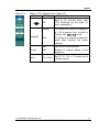
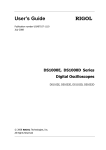
Download User's Guide RIGOL
Transcript
User’s Guide RIGOL Publication number UGA04107-1210 July 2008 DS1000B Series Digital Oscilloscopes DS1062/4B,DS1102/4B,DS1202/4B © 2008 RIGOL Technologies, Inc. All Rights Reserved RIGOL © 2008 RIGOL Technologies, Inc. All Rights Reserved. RIGOL products are protected by patent law in and outside of P.R. China. Information in this publication replaces all previously corresponding material. RIGOL Technologies, Inc. reserves the right to modify or change part of or all the specifications and pricing policies at company‟s sole decision. NOTE: RIGOL is registered trademark of RIGOL Technologies, Inc. © 2008 RIGOL Technologies, Inc. User‟s Guide for DS1000B Series I RIGOL Safety Notices Review the following safety precautions carefully to avoid any personal injuries or damages to the instrument and any products connected to it. To avoid potential hazards, please use the instrument as specified by this manual only. The instrument should be serviced by Authorized personnel only. To Avoid Fire or Personal Injury. Use Proper Power Cord. Use the power cord designed for the instrument and authorized in your country only. Ground The Instrument. The oscilloscope is grounded through the grounding conductor of the power cord. To avoid electric shock the instrument, grounding conductor(s) must be grounded properly, before making connections to the input or output terminals of the instrument. Connect The Probe. The probes‟ ground terminals are at the same voltage level of the instrument ground. Do not connect the ground terminals to a high voltage. Observe All Terminal Ratings. To avoid fire or shock hazard, observe all ratings and marks on the instrument. Follow the user‟s guide for further ratings information before making connections to the instrument. Do Not Operate Without Covers. Do not operate the instrument with covers or panels removed. Use Proper Fuse. Use the fuse of the type, voltage and current ratings as specified for the instrument. Avoid Circuit or Wire Exposure. Do not touch exposed connections and components when power is on. Do Not Operate With Suspected Failures. If suspected damage occurs with the instrument, have it inspected by qualified service personnel before further operations. Provide Proper Ventilation. Refer to the installation instructions for proper ventilation of the instrument. Do not Operate in Wet/Damp Conditions. II © 2008 RIGOL Technologies, Inc. User‟s Guide for DS1000B Series RIGOL Do not Operate in an Explosive Atmosphere. Keep Product Surfaces Clean and Dry. The disturbance test of all the models meet the limit values of A in the standard of EN 61326: 1997+A1+A2+A3, but can’t meet the limit values of B. Measurement Category The DS1000B series Digital Oscilloscope is intended to be used for measurements in Measurement Category I. Measurement Category Definitions Measurement Category I is for measurements performed on circuits not directly connected to MAINS. Examples are measurements on circuits not derived from MAINS, and specially protected (internal) MAINS derived circuits. In the latter case, transient stresses are variable; for that reason, the transient withstand capability of the equipment is made known to the user. WARNING IEC Measurement Category I. The input terminals may be connected to circuit terminal in IEC Category I installations for voltages up to 300 VAC. To avoid the danger of electric shock, do not connect the inputs to circuit‟s voltages above 300 VAC. Transient overvoltage is also present on circuits that are isolated from mains. The DS1000B series Digital Oscilloscopes is designed to safely withstand occasional transient overvoltage up to 1000 Vpk. Do not use this equipment to measure circuits where transient overvoltage could exceed this level. © 2008 RIGOL Technologies, Inc. User‟s Guide for DS1000B Series III RIGOL Safety Terms and Symbols Terms in This Guide. These terms may appear in this guide: ! WARNING: Warning statements identify conditions or practices that could result in injury or loss of life. ! CAUTION: Caution statements identify conditions or practices that could result in damage to this product or other property. Terms on the Product: These terms may appear on the product. DANGER indicates an injury hazard may be immediately accessible. WARNING indicates an injury hazard may be not immediately accessible. CAUTION indicates that a potential damage to the instrument or other property might occur. Symbols on the Product: These symbols may appear on the Instrument: ! Hazardous Voltage IV Refer to Instructions Protective Chassis Earth Terminal Ground Earth Ground © 2008 RIGOL Technologies, Inc. User‟s Guide for DS1000B Series RIGOL General-Purpose Oscilloscopes RIGOL DS1000B series digital oscilloscopes offer exceptional waveform viewing and measurements in a compact, lightweight package. The DS1000B series is ideal for production test, field service, research, design, education and training involving applications of analog circuit tests and troubleshooting. Product features: Dual Channel or Four Channels, Bandwidth of per channel: 200MHz (DS1202/4B) 100MHz (DS1102/4B) 60MHz (DS1062/4B) 2GSa/s real-time sampling rate and 50GSa/s equivalent sampling rate. Color TFT 5.7 inch LCD, 320× 240 pixels resolution. USB storage and direct printing, software upgrade via USB interface. Adjustable waveform intensity, more effective waveform viewing. One-touch automatic setup, ease of use (AUTO). Storage and recurrence of Waveforms and setups, supports CSV, 8 or 24 bits bitmap and PNG format. Delayed Scan Function, easy to give attention to both details and overview of a waveform. 22 Automatic measurements. Automatic cursor tracking measurements. Waveform recorder, record and replay dynamic waveforms. Supports fast offset calibration of an oscilloscope. Built-in FFT function. Digital filters, includes LPF, HPF, BPF, BRF. Pass/Fail detection Function, optically isolated Pass/Fail output. Add, Subtract and Multiply Mathematic Functions of waveforms. Advanced trigger types include: Edge, Video, Pulse width, Pattern, Alternative. Adjustable trigger sensitivity. Multiple Language User Interface. Pop-up menu makes it easy to read and easy to use. Built-in help systems with multinational languages. Easy-to-use file system supports Chinese & English characters file name input. Conform to LXI consortium instrument standard class C. © 2008 RIGOL Technologies, Inc. User‟s Guide for DS1000B Series V RIGOL Contents Safety Notices ...........................................................................................II General-Purpose Oscilloscopes ................................................................... V Chapter 1 : Getting Started ................................................................. 1-1 The Front Panel and User Interface ......................................................... 1-2 To Inspect the Instrument ...................................................................... 1-5 To Perform a Functional Check ................................................................ 1-6 To Compensate the Probes ..................................................................... 1-8 To Display a Signal Automatically ............................................................ 1-9 To Understand the Vertical System ........................................................ 1-10 To Understand the Horizontal System .................................................... 1-12 To Trigger the Oscilloscope ................................................................... 1-14 To Understand the Quick Function ......................................................... 1-17 Chapter 2 : Operating Your Oscilloscope ............................................ 2-1 To Set up the Vertical System ................................................................. 2-2 To Set the Channels ......................................................................... 2-2 To Use Math Functions ................................................................... 2-13 To Use REF Function ...................................................................... 2-18 Turn on or off Channels .................................................................. 2-26 To Apply the Vertical Knobs ............................................................ 2-27 To Set up the Horizontal System ........................................................... 2-28 To Set up the Trigger System................................................................ 2-34 Trigger Modes ............................................................................... 2-35 Edge Trigger.................................................................................. 2-36 Pulse Width Trigger........................................................................ 2-37 Video Trigger ................................................................................. 2-38 Pattern Trigger .............................................................................. 2-41 Alternative Trigger ......................................................................... 2-43 Trigger Settings ............................................................................. 2-46 To Set up the Sampling System ............................................................. 2-52 To Set up the Display System ................................................................ 2-56 To Store and Recall .............................................................................. 2-59 To Set up the Utility ............................................................................. 2-69 The I/O Setup ............................................................................... 2-71 Preference .................................................................................... 2-74 Self-Calibration .............................................................................. 2-75 VI © 2008 RIGOL Technologies, Inc. User‟s Guide for DS1000B Series RIGOL Pass/Fail ........................................................................................ 2-76 Print Setting ................................................................................... 2-80 Waveform Recorder ........................................................................ 2-82 System information ........................................................................ 2-86 Language ...................................................................................... 2-87 Date and Time ............................................................................... 2-88 To Measure Automatically ...................................................................... 2-89 Quick Measurement Setup .............................................................. 2-91 Delay/Phase Setup ......................................................................... 2-92 Voltage Measurements.................................................................... 2-93 Time Measurements ....................................................................... 2-95 To Measure with Cursors ....................................................................... 2-99 Manual Mode ............................................................................... 2-100 Track Mode .................................................................................. 2-102 Auto mode ................................................................................... 2-104 To Use Run Control Buttons ................................................................. 2-105 Chapter 3 : Application & Examples ....................................................3-1 Example 1: Taking Simple Measurements .................................................3-1 Example 2: View a Signal Delay Caused by a Circuit ..................................3-2 Example 3: Capture a Single-Shot Signal ..................................................3-3 Example 4: To Reduce the Random Noise on a Signal ...............................3-4 Example 5: Making Cursor Measurements .................................................3-6 Example 6: The Application of the X-Y operation .......................................3-8 Example 7: Triggering on a Video Signal ................................................. 3-10 Example 8: FFT Cursor Measurement ..................................................... 3-12 Example 9: Pass/Fail Test ...................................................................... 3-14 Chapter 4 : Troubleshooting ...............................................................4-1 Chapter 5 : Specifications ...................................................................5-1 Specifications .........................................................................................5-2 General Specifications .............................................................................5-6 Chapter 6 : Appendixes .......................................................................6-1 Appendix A: Accessories ..........................................................................6-1 Appendix B: Warranty .............................................................................6-2 Appendix C: Maintenance ........................................................................6-3 Appendix D: Contact RIGOL ...................................................................6-4 Index ......................................................................................................... i © 2008 RIGOL Technologies, Inc. User‟s Guide for DS1000B Series VII RIGOL Chapter 1 : Getting Started This chapter covers the following topics: The front panel and user interface To inspect the instrument To perform a functional check To compensate the probes To display a signal automatically To understand the vertical system To understand the horizontal system To trigger the oscilloscope To understand the quick function © 2008 RIGOL Technologies, Inc. User‟s Guide for DS1000B Series 1-1 RIGOL The Front Panel and User Interface Being familiar with the front panel of an oscilloscope is the first priority when you get a new type digital oscilloscope. This chapter will bring you a brief introduction and description of the front panel operations of DS1000B series digital oscilloscopes. It is a great help for your understanding to the layout of the knobs and keys and how to use them. Read the chapter carefully before further operations. Figure 1-1, the front Panel; the knobs are used most often and are similar to the knobs on other oscilloscopes. There are five gray buttons defined as No.1 to No.5 from up to bottom on the right side of the display which are menu operating buttons. The buttons not only allow you to use some of the functions directly but also bring up soft button menus on the screen, which enable the access to many measurement features associated with the advanced functions, mathematics, and reference or to run control features. Figure 1-1 DS1000B Series Oscilloscope‟s Front Panel 1-2 User‟s Guide for DS1000B series © 2008 RIGOL Technologies, Inc. RIGOL Figure 1-2 Front Panel Controls Notation definitions in this User’s Guide: Throughout this guide, notation symbols of buttons and knobs are the same of those on front-panel. A box around the name of the key denotes MENU function buttons on front-panel, such as Measure. ( ) denotes the multi-function knob . denotes the three POSITION knobs (two channels) or five POSITION knobs (four channels) denotes the three or five SCALE knobs according to the quantities of the channels of different types of oscilloscopes. denotes the LEVEL knob. The name with a drop shadow denotes the menu operating key, such as Waveform soft key in Storage menu. © 2008 RIGOL Technologies, Inc. User‟s Guide for DS1000B Series 1-3 RIGOL Location of the current waveform in the memory Running status Trigger position in the memory Trigger position in current waveform windows Trigger symbol Mark of channel1 Menu Mark of channel2 Mark of channel3 Mark of channel4 Waveform display windows Figure 1-3 Display screen 1-4 User‟s Guide for DS1000B series © 2008 RIGOL Technologies, Inc. RIGOL To Inspect the Instrument After receiving a new DS1000B series oscilloscope, please inspect the instrument as follows: 1. Inspect the shipping container for damage. Keep the damaged shipping container or cushioning material until the contents of the shipment have been checked for completeness and the instrument has been checked mechanically and electrically. 2. Check the accessories. Accessories supplied with the instrument are listed in "Accessories" in this guide. If the contents are incomplete or damaged notify the RIGOL Sales Representative. 3. Inspect the instrument. In case there is any mechanical damage or defect, or the instrument does not operate properly or fails performance tests, notify the RIGOL Sales Representative. If the shipping container is damaged, or the cushioning materials show signs of stress, notify the carrier as well as the RIGOL sales office. Keep the shipping materials for the carrier‟s inspection. RIGOL offices will arrange for repair or replacement at RIGOL‟s option without waiting for claim settlement. © 2008 RIGOL Technologies, Inc. User‟s Guide for DS1000B Series 1-5 RIGOL To Perform a Functional Check Perform this quick functional check to verify that the instrument is operating correctly. 1. Turn on the instrument. Use the power cord designed for the oscilloscope only. Use a power source that delivers 100 to 240 V, 45Hz to 440Hz. Turn on the instruments, and wait until the display shows the waveform window. Push the Storage button, select Storage in the top menu box and push the Factory menu box, then continue pressing Load. Storage button Power Figure 1-4 Turn on the instrument ! WARNNING: To avoid electric shock, be sure the oscilloscope is properly grounded. 2. Input a signal to a channel of the oscilloscope ① Set the attenuation switch on the probe to 10X and connect the probe to Channel 1 on the oscilloscope. To do this: Align the slot in the probe connector with the socket on the Bayonet Nut Connector (BNC) connector of CH1 or CH2. Push to connect, and twist to the right to lock the probe in place. Attach the probe tip and ground lead to the PROBE COMP connector. 1-6 User‟s Guide for DS1000B series © 2008 RIGOL Technologies, Inc. RIGOL Probe compensator Figure 1-5 Attach the probe ② Set the probe attenuation of the oscilloscope to 10X. To do this, push CH1→Probe→10X. Probe scale Figure 1-6 Set the probe Figure 1-7 The CH1 menu ③ Push the AUTO button. Within a few seconds, a square wave will be displayed on the screen. ④ Push the OFF button or push the CH1 button again to turn off Channel 1. Push the CH2, CH3, CH4 buttons to turn on channel 2, channel3, channel4, repeat steps 2 and 3. NOTE: The signal output from Probe compensator should only be used for probe compensation, not for calibration. © 2008 RIGOL Technologies, Inc. User‟s Guide for DS1000B Series 1-7 RIGOL To Compensate the Probes Perform this adjustment to match the characteristics of the probe and the channel input. This should be performed whenever attaching a probe to any input channel at the first time. 1. From CH1 menu, set the Probe attenuation to 10X (press CH1→Probe→10X). Set the switch to 10X on the probe and connect it to CH1 of the oscilloscope. When using the probe hook-tip, inserting the tip into the hook-tip firmly to ensure a tight connection. Attach the probe tip to the connector of the Probe compensator and link the reference wire cramp with the ground connector of the probe compensator, Select CH1, and then press AUTO. 2. Check the shape of the displayed waveform. Over Compensated Correctly Compensated Under Compensated Figure 1-9 Figure 1-8 Check the shape 3. If necessary, use a non-metallic tool to adjust the variable capacitor of the probe for the flattest square wave being displayed on the oscilloscope. 4. Repeat if necessary. ! 1-8 WARNNING: To avoid electric shock while using the probe, be sure the perfection of the insulated cable, and do not touch the metallic portions of the probe head while it is connected with a voltage source. User‟s Guide for DS1000B series © 2008 RIGOL Technologies, Inc. RIGOL To Display a Signal Automatically The DS1000B series oscilloscope has an automated feature to display the input signal in best-fit status. The input signal should be 50 Hz or higher and a duty cycle is greater than 1%. Press the AUTO button, the oscilloscope automatically sets up VERTICAL, HORIZONTAL and TRIGGER controls to display the input signal. Adjust the controls manually to get the best results if necessary. Using the automatic setting: 1. Connect a signal to the oscilloscope (such as channel 1) as described above. 2. Press AUTO. The oscilloscope may change the current settings to display the signal; adjusts the vertical and horizontal scaling, the trigger coupling, type, position, level, and mode. © 2008 RIGOL Technologies, Inc. User‟s Guide for DS1000B Series 1-9 RIGOL To Understand the Vertical System As shown in Figure 1-9, there are several series buttons and knobs in the VERTICAL control area. The following exercises will gradually conduct you to be familiar with the using of the vertical parameters settings. Figure 1-9 The vertical control window 1. Center the signal on the display with the knob. The knob moves the signal vertically, and it is calibrated. Note that turning the knob, a voltage value is displayed for a short time indicating its value with respect to the ground reference located at the center of the screen. Also notice that the ground symbol on the left side of the display moves in conjunction with the knob. Measurement hints If the channel is DC coupled, measuring the DC and AC components of the signal by simply noting its distance from the ground symbol. If the channel is AC coupled, the DC component of the signal is blocked, allow you to use greater sensitivity to display the AC component of the signal. 1-10 User‟s Guide for DS1000B series © 2008 RIGOL Technologies, Inc. RIGOL Vertical offset back to 0 shortcut key Turn the knob to change the vertical display position of channel and press the knob to set the vertical display position back to 0 as a shortcut key, this is especially helpful when the trace position is far out of the screen and want it to get back to the screen center immediately. 2. Change the vertical setup and notice that each change affects the status bar differently. Change the vertical sensitivity with the knob and notice the change in the status bar at the bottom of the display. When you Press CH1, CH2, CH3, CH4, MATH, REF, the operating menus, symbols, waveforms and status information of corresponding channel and settings will be displayed on the screen. The current selected channel will be shut down when you press the key associated with the channel one more time. Coarse/Fine Shortcut key The Coarse/Fine vertical control can be set by simply pressing the vertical knob. © 2008 RIGOL Technologies, Inc. User‟s Guide for DS1000B Series 1-11 RIGOL To Understand the Horizontal System Figure 1-10 shows the HORIZONTAL controls: MENU button, and knobs of horizontal system. Following the exercise to familiarize with the buttons, knobs, and status bar. Figure 1-10 The horizontal system 1. Turn the knob and notice the change in the status bar. The horizontal knob changes the sweep speed in a 1-2-5 step sequence, and displays the value at the upper-left of the display. The time base ranges of the DS1000B series is from 5 ns/div* to 50 s/div. * NOTE: The speed of horizontal scan varies by different models. Delayed Scan Shortcut key To press the knob in the horizontal control area on the front-panel is another way to enter or exit Delayed Scan mode and it is equal to the menu operations, MENU→Delayed→ON. 1-12 User‟s Guide for DS1000B series © 2008 RIGOL Technologies, Inc. RIGOL 2. The horizontal on the waveform window. knob moves displayed signal horizontally The horizontal knob adjusts the trigger offset of signal, when turning the knob; you can note that the waveform moves horizontally in conjunction with the knob. Horizontal offset back to 0 shortcut key Press the knob to set the horizontal offset to 0 as a shortcut key, this is especially helpful when the trigger point is far out of the screen and want it to get back to the screen center immediately. 3. Press the MENU key to display the Time menu. You can enter or exit the Delayed Scan mode, toggle the display mode among Y-T, X-Y or ROLL mode, and turn the horizontal knob to adjust trigger offset. Horizontal position control Trig-Offset: Denotes the real position of the trigger point relative to the midpoint of the memory. In this setting, the trigger position will be changed horizontally when you turning the knob. © 2008 RIGOL Technologies, Inc. User‟s Guide for DS1000B Series 1-13 RIGOL To Trigger the Oscilloscope Figure 1-11 shows the TRIGGER control: MODE, MENU, FORCE, 50% and a knob. Following the exercises to familiarize with the buttons, trigger level knob and status bar. Figure 1-11 The trigger control window Three kinds of trigger modes can be switched among Auto, Normal and Single with pressing MODE button. 1. Use knob to change the settings of trigger level. Turning the knob, you will observe a nacarat trigger line, a trigger sign and a trigger level value displaying pane on the screen moving up and down. When you stop turning the knob, the trigger line, trigger sign and trigger value pane will disappear in five seconds. During the same time of moving the trigger line, you will notice that the displayed value of trigger level has been changed on the screen. 双 Trigger Level back to 0 Shortcut key Turn the 1-14 knob to change the trigger level value and press the knob to set trigger level back to 0 as a shortcut key. User‟s Guide for DS1000B series © 2008 RIGOL Technologies, Inc. RIGOL 2. Change the trigger setup and notice these changes in the status bar. Press MENU button in the Trigger control area. A soft button menu appears on the display showing the trigger setting choices as shown in Figure 1-12. · Press No.1 menu operating button to choose trigger mode as Edge. · Press No.2 menu operating button to choose trigger source as CH1. · Press No.3 menu operating button to choose slope type as · Press No.4 menu operating button to choose sweep mode as Auto. · Press No.5 menu operating button to enter secondary menu of . Trigger Set Up, so as to perform a further configuration about Trigger Coupling modes, trigger sensitivities, and trigger holdoff Figure 1-12 time. NOTE: The change of trigger mode, source selection and slope type will lead to the change of the status bar on the upper-right of the screen. 3. Press 50% Press the 50% button to set the trigger level to the center of the signal‟s amplitude. 4. Press FORCE Start an acquisition even if no valid trigger signal has been found, usually used in “Normal” or “Single” trigger mode. This button has no effect if the acquisition is already stopped. © 2008 RIGOL Technologies, Inc. User‟s Guide for DS1000B Series 1-15 RIGOL Key point: Holdoff: A time interval before the oscilloscope responses to next trigger signal. During this Holdoff period, the trigger system becomes “blind” to trigger signals. This function helps to view complex signals such as an AM waveform. Press Holdoff button to activate ( ) knob, then turn it to adjust Holdoff time. 1-16 User‟s Guide for DS1000B series © 2008 RIGOL Technologies, Inc. RIGOL To Understand the Quick Function The following figure shows that there are two buttons in the QUICK function area. The exercise below will gradually conduct you to familiarize the settings of the buttons. Figure 1-13 The quick function menu 1. Firstly, you need to press the button Measure form the main MENU, then press the button associated with QuickMea, you will navigate into the quick measurement setting menu. Three measuring items can be pre-set from the 22 measurements. Now, Press Measure button from the quick control area to enter quick measurement, three measuring parameters pre-defined will be displayed on the screen. 2. Use Print button to perform a quick print, you can set screen quantities need to be printed or store datum to the USB disk. © 2008 RIGOL Technologies, Inc. User‟s Guide for DS1000B Series 1-17 RIGOL Chapter 2 : Operating Your Oscilloscope By now, a user should understand the VERTICAL, HORIZONTAL and TRIGGER control systems and know how to determine the system setup from the status bar of a DS1000B series digital oscilloscope. This chapter will go through all groups of front-panel buttons, knobs and menus; and further the knowledge of the operation by hints in this guide. It is strongly recommended to perform all of the following exercises to get the most of the powerful measurement capabilities of the oscilloscope. The following topics will be elaborated in this chapter: To set up the vertical system ( CH1, CH2, CH3, CH4, MATH, REF , Vertical To set up the horizontal system , Vertical (MENU, Horizontal Horizontal To set up the trigger system (MODE, To set up the sampling system (Acquire) To set up the display system (Display) To save and recall waveforms or setups ) , ) , MENU, FORCE, 50%) (Storage) To set up utility (Utility) To measure automatically (Measure) To measure with cursors (Cursor) To use run control buttons (Auto, Run/Stop, Single) © 2008 RIGOL Technologies, Inc. User‟s Guide for DS1000B Series 2-1 RIGOL To Set up the Vertical System To Set the Channels Each channel of DS1000B series digital oscilloscope has an independent operation menu and it will pop-up after pressing any button among CH1, CH2, CH3, CH4. The settings of all items in the menu are shown in the table below. Figure 2-1 Table 2-1 The Channel menu (Page 1/2) Menu Settings AC Coupling DC GND ON BW Limit OFF 0.001X . . 1000X Probe Digital filter Restraint the DC component of the input signal and passes the AC component with frequency higher than 5Hz. Passes both AC and DC components of the input signal Disconnect the input signal. Limit the channel‟s bandwidth to 20MHz to reduce display noise. Get full bandwidth. Set up the oscilloscope‟s probe attenuation factor to make the vertical scale readout correct. Set up digital filter (See table 2-4). 1/2 2-2 Comments Go to the next menu page (The followings are the same, no more explanation). User‟s Guide for DS1000B series © 2008 RIGOL Technologies, Inc. RIGOL Figure 2-2 Table 2-2 The Channel menu (Page 2/2) Menu Settings 2/2 Coarse Volts/Div Fine Invert ON OFF Unit V/ A/ W/ U Comments Back to the previous menu page (The followings are the same, no more explanation). To change the Volts/Dive settings in a 1-2-5 sequence from 2mv/div to 10v/div with knob. To change the Volts/Dive settings in small steps between the coarse settings. Turn on the invert function. Restore to original display of the waveform. Set “V”, “A”, “W” or “U” as the unit of vertical channel. © 2008 RIGOL Technologies, Inc. User‟s Guide for DS1000B Series 2-3 RIGOL To set up channel coupling To use Channel 1 as an example, input a square wave signal with DC shift. Press CH1→Coupling→DC to set “DC” coupling. Both the AC component and the DC component of the input signal will pass. The waveform is displayed as Figure 2-3: DC coupling Setup DC coupling Status symbol Figure 2-3 Waveform display Press CH1→Coupling→AC, to set “AC” coupling. It will pass AC component of the input signal with frequency higher than 5 Hz and restraint DC component of the input signal. The waveform is displayed as Figure 2-4: 2-4 User‟s Guide for DS1000B series © 2008 RIGOL Technologies, Inc. RIGOL AC coupling Setup AC coupling Status symbol Figure 2-4 Waveform display Press CH1→Coupling→GND, to set “GND” coupling, it disconnects the input signal. The screen displays as Figure 2-5: GND coupling Setup GND coupling Status symbol Figure 2-5 Screen display © 2008 RIGOL Technologies, Inc. User‟s Guide for DS1000B Series 2-5 RIGOL To set up the channel bandwidth limit Take Channel 1 for an example, input a signal containing high frequency component. Press CH1→BW Limit→OFF, to set up bandwidth limit to “OFF” status. The oscilloscope is set to full bandwidth and passing the high frequency component in the signal. The waveform is displayed as Figure 2-6: Turn off the BW limit Figure 2-6 Turn off the BW limit Press CH1→BW Limit→ON, to set up bandwidth limit to “ON” status. It will restraint the frequency component higher than 20MHz. The waveform is displayed as Figure 2-7: 2-6 User‟s Guide for DS1000B series © 2008 RIGOL Technologies, Inc. RIGOL 20MHz BW limit Mark of BW limit Figure 2-7 Turn on the BW limit © 2008 RIGOL Technologies, Inc. User‟s Guide for DS1000B Series 2-7 RIGOL To set up Probe Attenuation The oscilloscope allows selecting the attenuation factor for the probe. The attenuation factor changes the vertical scaling of the oscilloscope so that the measurement results reflect the actual voltage levels at the probe tip. To change (or check) the probe attenuation setting, press the CH1, CH2, CH3 or CH4 button (according to which channel is in using). Toggle the Probe soft button to match the attenuation factor of the probe. This setting remains in effect until changed again. Figure 2-8 shows an example for using a 1000:1 probe and its attenuation factor. Probe attenuation Vertical volt/div. Figure 2-8 Using a 1000:1 probe Table 2-3 Probe setting 2-8 Probe attenuation factors Corresponding settings 1:1000,1:100,1:10 0.001X,0.01X,0.1X 1:1,2:1,5:1 1X,2X,5X 10:1,20:1,50:1 10X,20X,50X 100:1,200:1,500:1 100X,200X,500X 1000:1 1000X User‟s Guide for DS1000B series © 2008 RIGOL Technologies, Inc. RIGOL To change the Volts/Div settings The Volts/Div control has Coarse or Fine configuration. The Vertical Sensitivity is 2mv/div - 10V/div. Coarse: It is the default setting of Volts/Div in a 1-2-5-step sequence from 2mV/div, 5mV/div, 10mV/div, to 10 V/div. Fine: This setting changes the vertical scale to small steps between the coarse settings. It will be helpful to adjust the waveform in smooth steps. Fine adjustment Figure 2-9 Fine configurations Fine adjustment data Coarse/Fine Shortcut key: To change Coarse/Fine setting, not only by menu operation but also by pressing vertical knob. © 2008 RIGOL Technologies, Inc. User‟s Guide for DS1000B Series 2-9 RIGOL To invert a waveform Invert turns the displayed waveform 180 degrees with respect to the ground level. When the oscilloscope is triggered on the inverted signal, the trigger is also inverted. Figure 2-10 and Figure 2-11 show the changes before and after the inversion respectively. Invert off Figure 2-10 The waveform before inversion Invert on Figure 2-11 The waveform after inversion 2-10 User‟s Guide for DS1000B series © 2008 RIGOL Technologies, Inc. RIGOL To configure the Digital Filter Press CH1→ Digital filter, it will display the digital filter menu. Turn the digital filter on or off as shown in the following figure. Turn ( ) knob to adjust the upper and lower limit of frequency after turning on the digital filter. Turn off digital filter Figure 2-12 Turn off digital filter Turn on digital filter Figure 2-13 Turn on digital filter © 2008 RIGOL Technologies, Inc. User‟s Guide for DS1000B Series 2-11 RIGOL Figure 2-14 Table 2-4 The Filter menu Menu Settings Digital Filter On Off Comments Turn on the digital filter. Turn off the digital filter. Filter Type Setup Setup Setup Setup Upper limit Turn ( ) knob to set upper limit high limit. Lower limit <frequency> <frequency> Turn ( as as as as LPF (Low Pass Filter). HPF (High Pass Filter). BPF (Band Pass Filter). BRF (Band Reject Filter). ) knob to set lower limit. Back to higher level menu (The followings are the same, no more explanation). 2-12 User‟s Guide for DS1000B series © 2008 RIGOL Technologies, Inc. RIGOL To Use Math Functions The mathematic functions include “add”, “subtract”, “multiply” and “FFT” for Channel 1, Channel 2, Channel3 and Channel4. The mathematic result can be measured by the grid and the cursor. Math Scale Figure 2-15 The Math function Figure 2-16 Table 2-5 The Math menu (Page 1/2) Menu Operate Source A Source B Invert Settings A+B A-B A× B FFT CH1, CH2, CH3, CH4 CH1, CH2, CH3, CH4 ON OFF Comments Add source A and source B. Subtract source B from source A. Multiply source B by source A. Fast Fourier Transform. Define CH1, CH2, CH3 or CH4 as source A. Define CH1, CH2, CH3 or CH4 as source B. Invert the MATH waveform. Restore to original waveform display. © 2008 RIGOL Technologies, Inc. User‟s Guide for DS1000B Series 2-13 RIGOL Figure 2-17 Table 2-6 The Math menu (Page 2/2) Menu Settings Comments The multifunctional knob ( ) adjusts the vertical position of the Math waveform. The multifunctional knob ( ) adjusts the vertical amplitude of the Math waveform. 2-14 User‟s Guide for DS1000B series © 2008 RIGOL Technologies, Inc. RIGOL Using FFT function The FFT (Fast Fourier Transform) process converts a time-domain signal into its frequency components mathematically. FFT waveforms are useful in the following applications: Measuring harmonic content and distortion in systems Characterizing noise in DC power supplies Analyzing vibration Figure 2-18 Table 2-7 The FFT menu (Page 1/2) Menu Settings Comments Operate A+B A-B A× B FFT Add source A to source B. Subtract source B from source A. Multiply source B by source A. Fast Fourier Transform. Source CH1, CH2, CH3, CH4 Define CH1, CH2, CH3 or CH4 as FFT source. Window Rectangle Hanning Hamming Blackman Select window for FFT. Display Split Full screen Display FFT waveform on half screen. Display FFT waveform on full screen. © 2008 RIGOL Technologies, Inc. User‟s Guide for DS1000B Series 2-15 RIGOL Figure 2-19 Table 2-8 The FFT menu (Page 2/2) Menu Settings comments The multifunctional knob( ) adjusts the vertical position of Math The multifunctional knob( ) adjusts the vertical amplitude of Math Vertical scale Vrms dBVrms Set Vrms as vertical scale unit Set dBVrms as vertical scale unit Key points for FFT 1. 2. 3. 2-16 Signals that have a DC component or offset can cause incorrect FFT waveform component magnitude values. To minimize the DC component, choose AC Coupling on the source signal. To reduce random noise and aliases components in repetitive or single-shot events, set the oscilloscope acquisition mode to Average. To display FFT waveforms with a large dynamic range, use the dBVrms scale. The dBVrms scale displays component magnitudes using a log scale. User‟s Guide for DS1000B series © 2008 RIGOL Technologies, Inc. RIGOL Selecting an FFT Window DS1000B series oscilloscope provides four FFT windows. Each window is a trade-off between frequency resolution and amplitude accuracy. It depends on the desired measurement and the source signals characteristics to determine the window to use. Use the following guidelines to select the best window. Table 2-9 FFT Windows Window Features Best frequency resolution and worst amplitude accuracy. Rectangle This is essentially the same as no window. Hanning Better frequency resolution, poorer amplitude accuracy than Rectangular. Hamming Hamming has slightly better frequency resolution than Hanning. Blackman Best amplitude accuracy, worst frequency resolution. Best for measuring Transients or bursts, the signal levels before and after the event are nearly equal. Equal-amplitude sine waves with fixed frequencies. Broadband random noise with a relatively slow varying spectrum. Sine, periodic, and narrow-band random noise. Transients or bursts where the signal levels before and after the events are significantly different. Single frequency waveforms, to find higher order harmonics. Key points: FFT Resolution: The FFT resolution is the quotient between sampling rate and the number of FFT points. With a fixed FFT points, the lower sampling rate, the better the resolution. Nyquist Frequency The highest frequency that any real-time digitizing oscilloscope can acquire without aliasing. It‟s normally half of the sample rate. This frequency is called the Nyquist frequency. Frequency above the Nyquist frequency will be under sampled, causing a situation known as aliasing. © 2008 RIGOL Technologies, Inc. User‟s Guide for DS1000B Series 2-17 RIGOL To Use REF Function Reference Waveforms are saved waveforms to be selected for display. The reference function will be available after saving the selected waveform to non-volatile memory. During the actual measurement process, you can use DS1000B series digital oscilloscope to observe the waveforms of correlative components. It will help you to determine the cause of malfunction when you compare the measured waveform with the reference waveform. The method is particularly useful under the circumstance of having reference waveforms. Press REF button to display the Reference waveform menu. Figure 2-20 Table 2-10 REF menu when using internal memory (Page 1/3) Menu Settings REF 1 REF 2 REF 3 REF 4 Turn on or turn off one to four REF channels Current REF REF REF REF 1 2 3 4 Select the current REF channel which is optional from REF1 to REF4. (According to the available channel, for example, if only REF1 is turned on, then only REF1 can be chosen as the current channel.) Source CH1, CH2, CH3, CH4, MATH Select CH1, CH2, CH3,CH4,MATH as the source channel whose input waveforms will be compared with the reference waveforms. location Internal external Select memory location in scope. Select memory location out scope. Channel 2-18 Comments User‟s Guide for DS1000B series © 2008 RIGOL Technologies, Inc. RIGOL Figure 2-21 Table 2-11 REF menu when using internal/external memory (Page 2/3) Menu Settings Comments Save REF waveform to outer memory location. Save The multifunctional knob ( ) adjusts the vertical position of REF The multifunctional knob ( ) adjusts the vertical amplitude of REF Figure 2-22 Table 2-12 REF menu when using internal memory (Page 3/3) Menu settings comments Reset Reset REF waveform. Imp./Exp. Go to import menu (see table 2-14). Figure 2-23 Table 2-13 REF menu when using external memory (Page 3/3) Menu settings comments Reset Reset REF waveform. Import Go to import menu (see table 2-18). © 2008 RIGOL Technologies, Inc. User‟s Guide for DS1000B Series 2-19 RIGOL To Import and Export Press REF →Imp./Exp. and go to the following menu. Figure 2-24 Table 2-14 The Imp./Exp. Menu Menu Settings Explorer Path Directory File Comments Switch to Path, directory or file. Export Export the REF file from internal memory to external memory (see table 2-15). Import Import the REF file to internal memory. Delete File Delete file. The screen of Import and Export as follows Figure 2-25 Import of export the figure 2-20 User‟s Guide for DS1000B series © 2008 RIGOL Technologies, Inc. RIGOL Export Press REF→Imp./Exp.→ Export and go to the following menu. Figure 2-26 Table 2-15 The Export menu Menu Settings Comments Move the input focus point of files‟ name up and down. Move the focus point to next location. To delete chosen letter. Save Execute the operation. The screen of Export is as follows. Figure 2-27 Figure export © 2008 RIGOL Technologies, Inc. User‟s Guide for DS1000B Series 2-21 RIGOL Save to External Memory Press REF→Save and navigate to the following menu. Figure 2-28 Table 2-16 The Save menu Menu Settings Path Directory File Explorer Comments Switch among Path, Directory and File. New File (Folder) Set up new file in Path and File. Set up new folder in directory. Delete File (Folder) Delete chosen file (Folder). The screen of Save is as follows: Figure 2-29 The figure of save 2-22 User‟s Guide for DS1000B series © 2008 RIGOL Technologies, Inc. RIGOL New File (or New Folder) Press REF→Save→New File (or New Folder) and go to the following menu. Figure 2-30 Table 2-17 The New File menu Menu Settings Comments Move the focus point of file name up and down. Move the focus point to the next location. To delete chosen letter. Save Execute the saving operation. The screen of File Name input is as follows: The File name key in pane Switch Chinese/English Switch Capital on/off Figure 2-31 File Name inputting interface © 2008 RIGOL Technologies, Inc. User‟s Guide for DS1000B Series 2-23 RIGOL Import Press REF→Import and go to the following menu. Figure 2-32 Table 2-18 The Import menu Menu Settings Comments Explorer Path Directory File Switch among Path, Directory and File. Import the REF file into internal memory. Import The screen of Import is as follows: Figure 2-33 The figure of import 2-24 User‟s Guide for DS1000B series © 2008 RIGOL Technologies, Inc. RIGOL To Display a Reference Waveform Figure 2-34 Reference waveform display Push REF button to show the reference waveform menu. Continue Pressing button No.1 to turn on or turn off one to four reference channels. Select a REF channel as the current reference channel from the channels activated by step 2. Continue pressing button No.3 to select a signal source channel from CH1, CH2, CH3, CH4 and MATH.(If the MATH is not available ,press MATH button to activate MATH) Turn vertical knob , multifunctional knob , vertical knob to adjust the waveform (derived from step 4) to a suitable position and expand or express the waveform horizontally to a proper situation. Access page 1 of REF menu, Press button No.4 to select the saving location of REF waveform. Access page 2 of REF menu, and then press button No.2 to save the current waveform on the screen to internal or external memory as a reference waveform. NOTE: The Reference function is not available in X-Y mode. © 2008 RIGOL Technologies, Inc. User‟s Guide for DS1000B Series 2-25 RIGOL Turn on or off Channels CH1, CH2, CH3, CH4 and Ext. trigger channels are input channels. All functions applied will base on operating the instrument with channels, so MATH and REF can be regarded as relatively isolated channels. Press the corresponding button (for example: CH1, CH2, CH3, CH4, MATH, REF) on the front panel to turn the channels on. The backlight indicates the channel is currently active. When a channel is currently selected, press the button with respect to the channel again will turn it off and the backlight goes off. When a channel is not currently selected, press the button associated with the channel will select the channel as the current channel. Table 2-19 The Channels menu Channel Mode Settings ON Selected OFF Status Indicator Channel 2 (CH2) ON Selected OFF Channel 3(CH3) ON Selected OFF CH2 (sky blue letters with black background) CH2 (black letters with blue background) No indicator CH3(pink letters with black background) CH3(black letters with pink background) Channel 1 (CH1) Channel4(CH4) MATH 2-26 CH1 (yellow letters with black background) CH1 (black letters with yellow background) No indicator No indicator ON Selected OFF CH4(black letter with navy blue background) CH4(navy blue letter with black background) ON Selected OFF Math (black letter) Math (purple letter) No indicator No indicator User‟s Guide for DS1000B series © 2008 RIGOL Technologies, Inc. RIGOL To Apply the Vertical Knobs Use the vertical controls to display signal waveforms by adjusting the vertical knob, and the knob, and setting the input parameters. 1. Using vertical knob. The vertical control changes the vertical position of signal waveforms in all channels (excluding MATH and REF). The resolution changes according to the vertical level set. Pressing this knob will clear the channel‟s vertical offset to zero. 2. Using vertical knob. The vertical control changes the vertical sensitivity of signal waveforms in all channels (excluding MATH and REF). If the Volts/Div is set to “Coarse”, the waveform scales in a 1-2-5 step sequence from 2 mV ,5mv,10mv…to 10 V. If the Volts/Div is set to “Fine”, it scales to small steps between the coarse settings. Turn the knob clockwise to decrease the vertical scale, turn the knob counter-clockwise to increase the vertical Volts/Div setting. You can toggle between “coarse” and “Fine” setting through pressing the knob. 3. Channels(excluding vertical 4. Math and and REF ) would be adjustable by the only when they are selected. During the vertical positioning, a position message is displayed on the left bottom of the screen, in the same color along with the corresponding channel. The unit is V (Volts). © 2008 RIGOL Technologies, Inc. User‟s Guide for DS1000B Series 2-27 RIGOL To Set up the Horizontal System The oscilloscope shows the time per division in the scale readout. With the horizontal control buttons and knobs, you can change the horizontal time base and trigger offset which indicates the horizontal location of trigger in the memory. The horizontal controls change the horizontal scale and position of waveforms. The horizontal center of the screen is the time reference for waveforms. Changing the horizontal scale causes the waveform to be expanded or compressed with respect to the screen center. Horizontal position changes the displayed waveform position, relative to the trigger point. The Horizontal Knobs : The horizontal knob adjusts the horizontal position of all channel (including Math) waveforms. The resolution of this control varies with the time base. Pressing this button clears the trigger offset and moves the trigger point to the horizontal center of the screen. : Use to select the horizontal time/div (scale factor) for the main or the Delayed Scan time base. When Delayed Scan is enabled, it changes the width of the window zone by changing the Delayed Scan time base. Horizontal Menu. Press the horizontal MENU button to display the horizontal menu. The settings of this menu are listed in the following table. 2-28 User‟s Guide for DS1000B series © 2008 RIGOL Technologies, Inc. RIGOL Figure 2-35 Table 2-20 The Horizontal menu Menu Delayed Time Base Settings ON OFF Turn on the Delayed Scan mode. Turn off the Delayed Scan mode. Y-T Show the relative relation between vertical voltage and horizontal time. Show CH1 amplitude value at X axis; show CH2 amplitude value at Y axis. In Roll Mode, the waveform display updates from right to left. X-Y Roll Adjust the trigger position to the center of the memory. Trig-offset Reset ① Comments ② ③ ④ ⑤ Figure 2-36 Status bar and mark for Horizontal control © 2008 RIGOL Technologies, Inc. User‟s Guide for DS1000B Series 2-29 RIGOL Marks Indicator ① The horizontal time base (main time base). ② The position of the current waveform window in the memory. ③ The trigger position in the memory. ④ The trigger position in the current waveform windows. ⑤ The trigger‟s horizontal offset with respect to the center of the window. Key Points Y-T: The conventional oscilloscope display format. It shows that the voltage of a waveform record (on the vertical axis) varies along with time (on the horizontal axis). X-Y: XY format displays channel 1 in the horizontal axis and channel 2 in the vertical axis. Roll Mode: In this mode, the waveform display rolls from right to left. No trigger or horizontal offset control of waveforms is available during Roll Mode, and it‟s only available when set to 500ms/div or slower. Slow Scan Mode: This mode is available when the horizontal time base is set to 50ms or slower. In this mode, the oscilloscope acquires sufficient data for the left part to the trigger point, then wait for trigger, when trigger occurs, it continue to draw the rest part from the trigger point to the end of the right side. When choosing this mode to view low frequency signals, it is recommended that the channel coupling be set as DC. Time/Div: Horizontal scale. If the waveform acquisition is stopped (using the Run/Stop button), the Time/Div control expands or compresses the waveform. 2-30 User‟s Guide for DS1000B series © 2008 RIGOL Technologies, Inc. RIGOL Delayed Scan: The Delayed Scan is a magnified portion of the main waveform window. Use Delayed Scan to locate and horizontally expand part of the main waveform window for a more detailed (higher horizontal resolution) analysis of signal. The Delayed Scan time base setting cannot be set slower than the Main time base setting. Waveform to be horizontally expanded Time base of Delayed Scan Expanded waveform in horizontal Figure 2-37 Delayed Scan windows The following steps show you how to use Delayed Scan. 1. 2. Connect a signal to the oscilloscope and obtain a stable display. Press horizontal MENU→Delayed→ON or press horizontal knob to enter Delayed Scan mode. The screen will be split into two parts. The upper half displays the main waveform window and the lower half displays an expanded portion of the main waveform window. This expanded portion of the main window is called the Delayed Scan window. Two blocks shaded at the upper half; the un-shaded portion is expanded in the lower half. The horizontal and knobs control the size and position of the Delayed Scan. The value at top of the screen is the main time base and the value on the center bottom means the Delayed Scan time base. © 2008 RIGOL Technologies, Inc. User‟s Guide for DS1000B Series 2-31 RIGOL Use the horizontal portion. knob to change the position of the expanded Turn the horizontal To change the main time base, turn off the Delayed Scan mode. Since both the main and Delayed Scan waveform windows are displayed, each waveform window occupies a half of the original waveform window. They are both compressed vertically to a half size, the same as the vertical divisions. knob to adjust the Delayed Scan resolution. Delayed Scan Shortcut Key: Delayed Scan function can be activated not only by menu but also by pressing horizontal 2-32 knob. User‟s Guide for DS1000B series © 2008 RIGOL Technologies, Inc. RIGOL X-Y Format This format is useful for studying phase relationships between two signals. Channel 1 in the horizontal axis(X) and channel 2 in the vertical axis(Y), the oscilloscope uses a none-trigger acquisition mode, data is displayed as dots. Figure 2-38 X-Y display format NOTE: The X-Y display format is only suitable for CH1, CH2, CH3; CH4.In the normal condition, the oscilloscope can acquire waveforms with any sampling rate. You can also adjust the sampling rate and the vertical scaling of the channel when you use the X-Y display format. You can reduce the sampling rate so as to display a better Lissajous figure. The following modes or functions will not work in X-Y format. Cursor Measurements(excluding manual mode ) REF and MATH Operations Delayed Scan Mode Vector Display Mode Horizontal Trigger Controls(excluding MODE button) knob © 2008 RIGOL Technologies, Inc. User‟s Guide for DS1000B Series 2-33 RIGOL To Set up the Trigger System The trigger determines when the oscilloscope starts to acquire data and display a waveform. When a trigger is set up properly, it can convert unstable displays or blank screens into meaningful waveforms. When the oscilloscope starts to acquire a waveform, it collects enough data so that it can draw the waveform to the left of the trigger point. The oscilloscope continues to acquire data while waiting for the trigger condition to occur. After it detects a trigger, the oscilloscope continues to acquire enough data so that it can draw the waveform to the right of the trigger point. The trigger control area on the front panel includes a knob and four buttons: MODE : With the button, three kinds of trigger mode can be toggled among Auto, Normal, and Single. : 50%: FORCE: MENU: Use the knob to adjust the trigger level; press the knob to reset the trigger level to zero. Specify the trigger level to the vertical midpoint between the peaks of the trigger signal by pressing the instant execute button. Force to create a trigger signal and the function is mainly used in Normal and Single mode The button that activates the trigger controls menu. Figure 2-39 Trigger controls 2-34 User‟s Guide for DS1000B series © 2008 RIGOL Technologies, Inc. RIGOL Trigger Modes The oscilloscope provides five trigger modes: Edge, Pulse, Video, Pattern and Alternative. Edge: An edge trigger occurs when the trigger input passes through a specified voltage level in the specified slope direction. Pulse: Use this trigger mode to catch pulses with certain pulse width. Video: Use video trigger mode on fields or lines for standard video signals. Pattern: Recognising trigger by searching specified code. Alternative: Trigger on non-synchronized signals. © 2008 RIGOL Technologies, Inc. User‟s Guide for DS1000B Series 2-35 RIGOL Edge Trigger An edge trigger determines whether the oscilloscope finds the trigger point on the rising or the falling edge of a signal. Select Edge trigger Mode to trigger on Rising edge, falling edge or rising & falling edge. Figure 2-40 Table 2-21 The Trigger menu Menu Settings Comments Source CH1 CH2 CH3 CH4 EXT EXT/5 Select CH1 as trigger source. Select CH2 as trigger source. Select CH3 as trigger source. Select CH4 as trigger source. Select EXT TRIG as trigger source. Select attenuated EXT TRIG/5 as trigger source. Select power line as trigger source. AC Line Slope Rising edge Falling edge Rising & Falling edges Trigger on rising edge. Trigger on falling edge. Trigger on both ring & falling edge. Sweep Auto Acquire waveform even no trigger occurred. Acquire waveform when trigger occurred. When trigger occurs, acquire one waveform then stop. Normal Single Set up 2-36 To go to Set Up menu, see table 2-36 User‟s Guide for DS1000B series © 2008 RIGOL Technologies, Inc. RIGOL Pulse Width Trigger Pulse trigger occurs according to the width of pulse. The abnormal signals can be detected through setting up the pulse width condition. Figure 2-41 Table 2-22 The Trigger menu (Page 1/2) Menu Source Settings CH1 CH2 CH3 CH4 EXT Comments Select CH1 as trigger source. Select CH2 as trigger source. Select CH3 as trigger source Select CH4 as trigger source l Select EXT TRIG as trigger source Select attenuated EXT TRIG/5 as trigger source. EXT/5 (+Pulse width more than) (+Pulse width less than) When (+Pulse width equal to) (-Pulse width less than) To select pulse condition. (-Pulse width more than) (-Pulse width equal to) Settings <Width> To set required pulse width. Figure 2-42 Table 2-23 The Trigger menu (Page 2/2) Menu Sweep Set Up Settings Auto Normal Single Comments Acquire waveform even no trigger occurred. Acquire waveform when trigger occurred. When trigger occurs, acquire one waveform and then stop. To go to Set Up menu, see table 2-36. Note: The Pulse width adjust range is 20ns ~ 10s. When the condition is met, it will trigger and acquire the waveform. © 2008 RIGOL Technologies, Inc. User‟s Guide for DS1000B Series 2-37 RIGOL Video Trigger Choose video trigger to trigger on fields or lines of NTSC, PAL, or SECAM standard video signals. Trigger coupling preset to DC. Figure 2-43 Table 2-24 The Video Trigger menu (Page 1/2) Menu Source Settings CH1 CH2 CH3 CH4 EXT EXT/5 Normal polarity Polarity Sync 2-38 Inverted polarity All Lines Line Num Odd field Even field Comments Selects CH1 as trigger source. Selects CH2 as trigger source. Selects CH3 as trigger source. Selects CH4 as trigger source. Select EXT TRIG as trigger source. Select EXT TRIG/5 as trigger source. Triggers on positive going sync pulses. Triggers on negative going sync pulses. Trigger on all lines. Trigger on a specified line. Select to trigger on odd field. Select to trigger on even field. User‟s Guide for DS1000B series © 2008 RIGOL Technologies, Inc. RIGOL Figure 2-44 Table 2-25 The Video Trigger menu (Page 2/2 when Sync is set as the specified line) Menu Line Num Standard Settings < Line sync > PAL/SECM NTSC Auto Normal Sweep Single Set Up Comments Select the specified line number for sync. Select Video standard. Force the oscilloscope to trigger in the absence of trigger condition. Lets oscilloscope to trigger in the suitable trigger condition. Lets oscilloscope to trigger one time in the suitable trigger condition, and then stop. To go to set up menu, see Table 2-36. Figure 2-45 Table 2-26 The Video Trigger menu (Page 2/2 When the Sync is set as All lines, Odd field and Even field) Menu Settings Standard PAL/SECAM NTSC Auto Sweep Normal Single Set Up Comments Select Video standard. Force the oscilloscope to trigger in the absence of trigger condition. Lets oscilloscope to trigger in the suitable trigger condition. Lets oscilloscope to trigger one time in the suitable trigger condition, and then stop. To go to set up menu, see Table 2-36. © 2008 RIGOL Technologies, Inc. User‟s Guide for DS1000B Series 2-39 RIGOL Key points: Sync Pulses: When Normal Polarity is selected, the trigger always occurs on negative-going sync pulses. If the video signal has positive-going sync pulses, use the inverted Polarity. Figure 2-46 Video Trigger: Line Synchronization Figure 2-47 Video Trigger: Field Synchronization 2-40 User‟s Guide for DS1000B series © 2008 RIGOL Technologies, Inc. RIGOL Pattern Trigger Pattern trigger recognises the trigger condition through inspecting the code preset which means the logic values or the logic combination.Every channel has its own logic value,such as,logic high value,logic low value,and the neglect value. Figure 2-48 Table 2-27 The Pattern Trigger menu Menu Channel Settings Comments CH1 CH2 CH3 CH4 EXT EXT/5 To select CH1 as trigger source To select CH2 as trigger source To select CH3 as trigger source To select CH4 as trigger source To set EXT as trigger source To set EXT/5 as trigger source to expand trigger level range. To set the code of the selected channel as logic high value. To set the code of the selected channel as logic low value. To set the code of the selected channel as neglect value. To specify trigger to the rising edge of signal To specify trigger to the falling edge of signal Acquire waveform even no trigger occurred. Acquire waveform when trigger occurred. When trigger occurs, acquire one waveform then stop. H L Code X Auto Sweep Set up Normal Single To go to set up menu, see Table 2-36. © 2008 RIGOL Technologies, Inc. User‟s Guide for DS1000B Series 2-41 RIGOL Figure 2-49 Pattern trigger: set code as falling edge 2-42 User‟s Guide for DS1000B series © 2008 RIGOL Technologies, Inc. RIGOL Alternative Trigger When alternative trigger is on, the trigger sources come from two vertical channels. This mode can be used to observe two non-related signals. You can choose two different trigger modes for the two vertical channels. The options are as follows: Edge, Pulse and video. The info of the trigger level of the two channels will be displayed on the upper-right of the screen. Figure 2-50 Table 2-28 The Alternative trigger menu (Page 1/2 Trigger Type: Edge) Menu Figure 2-51 Settings Comments Alt Channel CH1-CH2 CH1-CH3 CH1-CH4 CH2-CH3 CH2-CH4 CH3-CH4 To specify the current alternative trigger channels as any two channels selected form CH1, CH2, CH3, CH4. select CH1, CH2 CH3, CH4 To select vertical channel among CH1, CH2, CH3, CH4 in alternative trigger mode so as to configure further settings. Type Edge Pulse Video Choose trigger type for the current channel. Table 2-29 The Alternative trigger menu (Page 2/2 Trigger Type: Edge) Menu settings comments Trigger on rising edge. Edge type ( rising edge) ( falling edge) ( both rising edge and falling edge) Set up Trigger on falling edge. Trigger on both ring & falling edge. To go to set up menu. See Table 2-36 © 2008 RIGOL Technologies, Inc. User‟s Guide for DS1000B Series 2-43 RIGOL Figure 2-52 Table 2-30 The Alternative trigger menu (Page 1/2 Trigger Type: Pulse) Menu Settings Alt Channel Figure 2-53 Comments CH1-CH2 CH1-CH3 CH1-CH4 CH2-CH3 CH2-CH4 CH3-CH4 To specify the current alternative trigger channels as any two channels selected form CH1, CH2, CH3, CH4. select CH1, CH2, CH3, CH4 To select vertical channel among CH1, CH2, CH3, CH4 in alternative trigger mode so as to configure further settings. type Edge trigger Pulse trigger Video trigger Select trigger channel. type for current Table 2-31 The Alternative trigger menu (Page 2/2 Trigger Type: Pulse) Menu Settings Comments (+Pulse width less than) (+Pulse width more than) (+Pulse width equal to) When (-Pulse width less than) (-Pulse width To set trigger conditions. more than) (-Pulse width equal to) Settings <Pulse width > To go to set up menu. See Table 2-36. Set Up 2-44 To set up width value of the pulse. User‟s Guide for DS1000B series © 2008 RIGOL Technologies, Inc. RIGOL Figure 2-54 Table 2-32 The Alternative trigger menu (Page 1/2 Trigger Type: Video) Menu Alt Channel Figure 2-55 Settings CH1-CH2 CH1-CH3 CH1-CH4 CH2-CH3 CH2-CH4 CH3-CH4 Comments To specify the current alternative trigger channels as any two channels selected form CH1, CH2, CH3, CH4. select CH1, CH2, CH3, CH4 To select vertical channel among CH1, CH2, CH3, CH4 in alternative trigger mode so as to configure further settings. Type Edge trigger Pulse trigger Video trigger To select trigger current channel. type for Table 2-33 The Alternative trigger menu (Page 2/2 Trigger Mode: Video) Menu Settings Normal polarity Polarity Sync Standard Set Up Inverted polarity Comments Trigger on negative going sync pulses. Trigger on positive going sync pulses. ALL lines Line Num Trigger on all lines. Trigger on a specified line. Odd field Even field Select to trigger on odd field or even field. PAL/SECM NTSC Select Video standard. To go to set up menu, see Table 2-36. © 2008 RIGOL Technologies, Inc. User‟s Guide for DS1000B Series 2-45 RIGOL Trigger Settings Set up different trigger settings according to different trigger modes. When in the mode of Video and Alternative, only trigger sensitivity, trigger holdoff time, holdoff reset is adjustable. Figure 2-56 Table 2-34 The Trigger Set Up menu (Page 1/2 Settings for trigger coupling, trigger sensitivity and Holdoff) Menu Coupling HF reject Sensitivity Holdoff 2-46 Settings Comments DC AC LF Reject Allow all signals pass. Block DC signals. Reject DC and low frequency signals. On Passes high frequency component. Blocks high frequency component, passes low frequency component. off <Sensitivity Setting> <Holdoff Setting> Set trigger sensitivity. Set time slot before another trigger event. User‟s Guide for DS1000B series © 2008 RIGOL Technologies, Inc. RIGOL Figure 2-57 Table 2-35 Restore the trigger holdoff time to default (page 2/2) Menu Holdoff Settings comments Reset Holdoff time to 100ns. When Settings for “sensitivity” and “Hold off” in the Video and Alternative trigger mode, the menu is shown below. Figure 2-58 Table 2-36 The Trigger Set Up menu Menu Sensitivity Holdoff Holdoff Reset Settings <Sensitivity Setting> <Holdoff Setting> Comments Set trigger sensitivity. Set time slot before another trigger event. Reset Holdoff time to 100ns. © 2008 RIGOL Technologies, Inc. User‟s Guide for DS1000B Series 2-47 RIGOL Trigger Holdoff You can use trigger Holdoff to stabilize a complex waveform, such as a pulse sequence. Holdoff time is the oscilloscope‟s waiting period before starting a new trigger. During Holdoff, oscilloscope will not trigger until Holdoff ends. For instance: To trigger on the first pulse on a group of them, users can set the holdoff time to Pulse cluster width. Trigger site Trigger holdoff Time of holdoff Figure 2-59 Trigger Holdoff To use trigger Holdoff: 1. Press the MENU button of the trigger control system to display the Menu. 2. Press Set Up key to display trigger set up menu. 3. Turn the multi function knob ( ) to change Holdoff time until waveform is stable. 4. Press Trigger Hold off reset to reset the Holdoff time to its default value. 2-48 User‟s Guide for DS1000B series © 2008 RIGOL Technologies, Inc. RIGOL Trigger Key points 1. Trigger Source: Trigger occurs from several sources: Input channels (CH1, CH2, CH3, CH4), AC Line, Ext, Ext/5. CH1, CH2, CH3, CH4: It is the most commonly used trigger source. The channel works when it is selected as a trigger source whatever displayed. Ext Trig: The instrument can be triggered from an external source while acquiring data from CH1, CH2, CH3, and CH4. For example, be a trigger source with an external clock or a signal from another part of the test circuit. The Ext, Ext/5 trigger sources use an external trigger signal connected to the EXT TRIG connector. Ext uses the signal directly; it has a trigger level range of -0.6 V to +0.6 V. The EXT/5 trigger source attenuates the signal by 5X, which extends the trigger level range to -3V to +3 V allowing the oscilloscope to trigger on a larger signal. AC Line: AC power can be used to display signals related to the power line frequency, such as lighting equipment and power supply devices. The oscilloscope gets triggered on its AC power input, but an AC trigger signal is not required. When AC Line is selected as a trigger source, the oscilloscope automatically set coupling to DC, set trigger level to 0V. 2. Sweep Mode: The sweep mode determines how the oscilloscope behaves in the absence of a trigger event. The oscilloscope provides three trigger modes: Auto, Normal, and Single. Auto: This sweep mode allows the oscilloscope to acquire waveforms even when it does not detect a trigger condition. If no trigger condition occurs while the oscilloscope is waiting for a specific period (as determined by the time-base © 2008 RIGOL Technologies, Inc. User‟s Guide for DS1000B Series 2-49 RIGOL setting), it will force itself to trigger. When forcing invalid triggers, the oscilloscope cannot synchronize the waveform, and the waveform seems to roll across the display. If valid triggers occur, the display becomes stable on the screen. Any factor results in the instability of waveforms can be detected by Auto Trigger, such as the output of Power supply. NOTE: When horizontal control is set under 50 ms/div, Auto mode allows the oscilloscope not to capture trigger signal. Normal: The Normal mode allows the oscilloscope to acquire a waveform only when it is triggered. If no trigger occurs, the oscilloscope keeps waiting, and the previous waveform will remain on the display. Single: In Single mode, after pressing the RUN/STOP key, the oscilloscope waits for trigger. While the trigger occurs, the oscilloscope acquires one waveform then stop. 3. Coupling: Trigger coupling determines which signal component passing to the trigger circuit. Coupling types include AC, DC, LF Reject and HF Reject. 4. AC: AC coupling blocks DC components and attenuate signal lower than 10 Hz. DC: DC coupling passes both AC and DC components. LF Reject: LF Reject coupling blocks DC component, and attenuates all signal with a frequency lower than 10 kHz. HF Reject: HF Reject coupling attenuates all signals with a frequency higher than 100 kHz. Pre-trigger/delayed trigger: The data is collected before and after trigger. The trigger position is typically set at the horizontal center of the screen. In the full-screen display the 6div data of pre-trigger and delayed trigger can be 2-50 User‟s Guide for DS1000B series © 2008 RIGOL Technologies, Inc. RIGOL surveyed. More data (14div) of pre-trigger and 1s delayed trigger can be surveyed by adjusting the horizontal knob. This feature is very useful to study the events that led up to the trigger point. Everything on the right of the trigger point is called post-trigger information. The delay range (pre-trigger and post-trigger information) depends on the sweep speed selected. 3. Adjustable trigger sensitivity To avoid the influence of noise from the physical world, and get the stable trigger, the trigger circuit has adopted Stickiness. In DS1000B series, the stickiness is adjustable from 0.1div-1.0div, which means when it sets to 1.0div; the trigger circuit will not affect any signal with peak-peak amplitude less than 1.0div, so as to avoid the influence of the noise. © 2008 RIGOL Technologies, Inc. User‟s Guide for DS1000B Series 2-51 RIGOL To Set up the Sampling System Figure 2-60 shows, the Acquire button at the MENU of the front panel. Acquire setup button Figure 2-60 The Acquire setup button Press the Acquire button, the interface menu shows as follows: Figure 2-61 Table 2-37 The Acquire menu Menu Settings Comments Acquisition Normal Average Peak Detect Normal Acquisition mode. Average Acquisition mode. Peak Detect Acquisition mode. Sampling Real-Time Equ-Time Real-time sampling mode. Equivalent sampling mode. Sinx/x ON OFF Set the interpolation as Sinx/x. Set the interpolation as linearity. Sa Rate 2-52 Display sampling rate. User‟s Guide for DS1000B series © 2008 RIGOL Technologies, Inc. RIGOL The waveform displayed on the screen will change in conjunction with the setting of Acquire menu. Figure 2-62 Signal that contains noise, and without average sampling Figure 2-63 Display signal after average 256 times sampling Note: Select Real-time acquisition to observe the single-shot or pulse signals. Select Equ-Time to observe high frequency repetitive signals. © 2008 RIGOL Technologies, Inc. User‟s Guide for DS1000B Series 2-53 RIGOL To reduce the displayed random noise, select the Average Acquisition. This mode would make the screen refresh slower. To Avoid signal aliasing, select Peak Detect Acquisition. Figure 2-64 Signal with Peak Detect Acquisition The Peak Detect effect is shown as the figure above. Stop Acquisition: When the scope is acquiring waveforms, the waveforms is in a live status; when acquisition is stopped, frozen waveform will be displayed, the position and scale can still be adjusted by vertical control and horizontal control. 2-54 User‟s Guide for DS1000B series © 2008 RIGOL Technologies, Inc. RIGOL Key Points Real-time Sampling: DS1000B has Real-time sampling rate up to 2GSa/s. At the time base 50ns or faster, the oscilloscopes use the sine(x)/x interpolation to expand the horizontal time base. Equivalent sampling: Known as Repetitive sampling to get up to 20ps of horizontal resolution (equivalent 50Gsa/s). This mode is good for observing repetitive signals, and it is not recommended for single-shot or pulse. Normal: Oscilloscope acquires signal by equal time interval. Average Acquisition: Apply averaging to your signal to remove uncorrelated noise and improve measurement accuracy. Reduces random or uncorrelated noise in the signal display. The averaged waveform is a running average over a specified number of acquisitions from 2 to 256. Peak Detect: Peak Detect mode captures the maximum and minimum values of a signal, and finds highest and lowest record points over many acquisitions. © 2008 RIGOL Technologies, Inc. User‟s Guide for DS1000B Series 2-55 RIGOL To Set up the Display System The menu button for the display system on the front panel is shown in the following figure. Display setup button Figure 2-65 The display setup button Press the Display button, the interface menu for settings shows as follows. Figure 2-66 Table 2-38 The Display menu (Page 1/3) Menu Type Setting Vectors Dots Infinite Persist OFF 2-56 Display waveforms as vectors. Display waveforms as dots. Clear all existing waveforms from screen. Clear Intensity Comments <percentage> The sample points remain displayed until turn the persistence “OFF”. Turn off the persistence function. Set up waveform intensity. User‟s Guide for DS1000B series © 2008 RIGOL Technologies, Inc. RIGOL Figure 2-67 Table 2-39 The Display menu (Page 2/3) Menu Grading Settings On Off Figure 2-68 The waveform is displayed multiple levels of pixel intensity. in Display grids and coordinates on the screen. Turn off the grids. Turn off the grids and coordinates. Grid Menu Display Comments 1s 2s 5s 10s 20s Infinite Set the time before menu fades away. The menu will be hidden after the set time of last button pressing. Table 2-40 The Display menu (Page 3/3) Menu GridBright Screen Settings <percentage> Normal Inverted Set up grid brightness. Set to normal mode. Set to invert color display mode. To show the last acquired waveform when the acquisition is stopped. To show the accumulated acquired waveforms when the acquisition is stopped. Screen persist Skin Comments Classical Modern Tradition Succinct To set the display screen of the oscilloscope © 2008 RIGOL Technologies, Inc. User‟s Guide for DS1000B Series 2-57 RIGOL Key points: Display type: Display type includes Vector and Dot. In vectors type, oscilloscope connects dots through digital interpolation including both linearity and sin(x)/x. Sin(x)/x interpolation is suitable for Real-time sampling and will be more effective at 50ns or faster time base. Refresh rate: It is an important performance of digital oscilloscopes. It means the number of display refreshing per second and it will affect the ability to observe signal. Adjusting waveform intensity Turn the multifunctional knob ( 2-58 ) to adjust waveform intensity. User‟s Guide for DS1000B series © 2008 RIGOL Technologies, Inc. RIGOL To Store and Recall Figure 2-69 shows the menu button for the storage system on the front panel. Storage setup button Figure 2-69 The Storage setup button Press the Storage button to show the menu for the settings of the storage system. Waveforms and setups can be stored in and recalled from both internal memory and external memory. The waveform files, setup files, 8 or 24 bits format bitmap files, CSV format files and PNG (Portable Network Graphics format) files in external memory can be created and deleted. System supports English/Chinese file name input. © 2008 RIGOL Technologies, Inc. User‟s Guide for DS1000B Series 2-59 RIGOL Waveform and setup menus are as follows: Figure 2-70 Table 2-41 The Storage menu Menu Storage Settings Comments Waveform Setups 8-Bitmap 24-Bitmap PNG CSV Factory Store or recall waveform. Store or recall instrument setups. Create or delete 8bits bitmap files. Create or delete 24bits bitmap files. Create or delete PNG format files. Create or delete CSV files. Recall factory setups. Internal Go to menu for internal memory operation (see Table 2-46). External Go to menu for external memory operation (see Table 2-47). Disk Mana. Go to disk manage menu (see Table 2-48). For factory default setups, the menu is as follows: Figure 2-71 Table 2-42 The Storage menu Menu Storage 2-60 Settings Comments Waveform Setups 8-Bitmap 24-Bitmap PNG CSV Factory Store or recall waveform. Store or recall instrument setups. Create or delete 8bits bitmap files. Create or delete 24bits bitmap files. Create or delete PNG format files. Create or delete CSV files. Recall factory setups. Load Recall factory setups or files. Disk Mana. Go to disk manage menu (see Table 2-48). User‟s Guide for DS1000B series © 2008 RIGOL Technologies, Inc. RIGOL For bitmap, the menu is as follows: Figure 2-72 Table 2-43 The Storage menu Menu Storage Settings Waveform Setups 8-Bitmap 24-Bitmap PNG CSV Factory Para Save On Off External Disk Mana. Comments Store or recall waveform. Store or recall setups. Create or delete 8bits Bitmap files. Create or delete 24bits Bitmap files. Create or delete Portable Network Graphics format files. Create or delete CSV files. Recall factory setups. Save the current oscilloscope settings in different format with the same file name. Go to menu for external memory operation (see Table 2-47). Go to disk manage menu (see Table 2-48). For CSV, the menu is as follows. Figure 2-73 Table 2-44 The Storage menu Menu Storage Data Depth Para Save External Disk Mana. Settings Comments Waveform Setups 8-Bitmap 24-Bitmap PNG CSV Factory Displayed Store or recall waveform. Store or recall instrument setups. Create or delete 8bits bitmap files. Create or delete 24bits bitmap files. Create or delete PNG format files. Create or delete CSV files. Recall factory setups. Save currently displayed waveform data to CSV file. Save the whole waveform data in memory to CSV file. Save the current oscilloscope settings in different format with the same file name. Go to menu for external memory operation (see Table 2-47). Go to disk manage menu (see Table 2-48). Maximum On Off © 2008 RIGOL Technologies, Inc. User‟s Guide for DS1000B Series 2-61 RIGOL For PNG, the menu is as follows. Figure 2-74 Table 2-45 The Storage menu Menu Storage Para Save Settings Comments Waveform Setups 8-Bitmap 24-Bitmap PNG CSV Factory On Store or recall waveform. Store or recall instrument setups. Create or delete 8bits bitmap files. Create or delete 24bits bitmap files. Create or delete PNG format files. Create or delete CSV files. Recall factory setups. Save the current oscilloscope settings in different format with the same file name. Go to menu for external memory operation (see Table 2-47). Go to disk manage menu (see Table 2-48). Off External Disk Mana. 2-62 User‟s Guide for DS1000B series © 2008 RIGOL Technologies, Inc. RIGOL Internal Memory Press Storage→Internal to go to the following menu. Figure 2-75 Table 2-46 The Memory menu Menu Settings Comments Internal Int_00 (N) . . . Int_09 (N) Set up the location of files in internal memory. Load Recall waveform files and setup files from the internal memory location. Save Save waveform files and setup files to the internal memory location. Delete Files Delete selected files. © 2008 RIGOL Technologies, Inc. User‟s Guide for DS1000B Series 2-63 RIGOL External Memory Press Storage→ External to go to the following menu. Figure 2-76 Table 2-47 The Memory menu Menu Settings Path Directory File Explorer Comments Switch among Path, Directory and File. New File (Folder) To create new file or folder.(see table 2-13) Delete File (Folder) Delete file (Folder). Load Recall waveform and setup from USB storage device. File system is as follows: Path Back to previous folder Files Current directory File info. Figure 2-77 File system display screen 2-64 User‟s Guide for DS1000B series © 2008 RIGOL Technologies, Inc. 
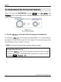
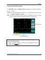
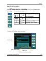
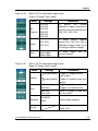
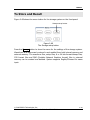
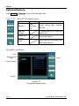
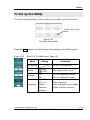
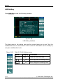
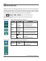
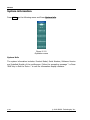
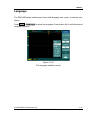
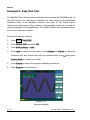
RIGOL U-disk Selection: Figure 2-78 U-disk selection DS1000B series have two USB Host ports on the front and rear panel. When both ports were inserted USB flash drive, the screen will appear a U-disk selection interface as Figure 2-78. Turn the multifunction knob to choose the driver. The front one marked “F:”, the rear one “G:”. © 2008 RIGOL Technologies, Inc. User‟s Guide for DS1000B Series 2-65 RIGOL Disk Management Press Storage→Disk Mana. to go to the following menu. Figure 2-79 Table 2-48 The Disk Management menu (Page 1/2) Menu Settings Path Directory File Explorer Figure 2-80 Switch among Path, Directory and File. New folder To create new folder (same as new files, see table 2-13). Delete File Delete selected file. Load Recall waveform, setup, recorded waveform, Pass/Fail file. Table 2-49 The Disk Management menu (Page 2/2) Menu 2-66 Comments Settings Comments Rename To rename a file (see Table 2-50). Disk info Display disk information. User‟s Guide for DS1000B series © 2008 RIGOL Technologies, Inc. RIGOL Rename Press Storage→Disk Mana.→Rename to go to the following menu. Figure 2-81 Table 2-50 The Rename menu Menu Settings Comments To move the input focus point of file name up and down. To move the focus point to the next location. To delete chosen letter. OK Rename the file. The Rename system screen is as follows: Figure 2-82 Rename the file © 2008 RIGOL Technologies, Inc. User‟s Guide for DS1000B Series 2-67 RIGOL Factory The oscilloscope has default settings and can be recalled at anytime by user. Memory location Specify the memory location to save/recall the waveforms and setups. Load Recall saved waveforms, setups and default settings. Save Save waveforms and setups. NOTE: 1. Select Save stores not only the waveforms, but also the current settings of the oscilloscope 2. To ensure the setups being saved properly, only after the settings are changed for more than 5 seconds, user could turn off the instrument. The oscilloscope can store 10 settings permanently and can restore at anytime. 2-68 User‟s Guide for DS1000B series © 2008 RIGOL Technologies, Inc. RIGOL To Set up the Utility The following figure shows the menu button for the Utility on the front panel. System function setup button Figure 2-83 The Utility setup button Press the Utility button to show the menu of the settings in the Utility system. Figure 2-84 Table 2-51 The Utility menu (Page 1/3) Menu Setting I/O setting Sound Counter Setup I/O configuration. (ON) (OFF) OFF ON 简体中文 繁体中文 Language Comments English Japanese Français Turn beeper sound on/off. Turn off Frequency Counter. Turn on Frequency Counter. Select languages. (More languages may be added in later firmware versions.) © 2008 RIGOL Technologies, Inc. User‟s Guide for DS1000B Series 2-69 RIGOL Figure 2-85 Table 2-52 The Utility menu (Page 2/3) Menu Figure 2-86 Settings Comments Pass/Fail Setup Pass/Fail test. Record Setup Waveform Recorder. Print set Setup printing. Table 2-53 The Utility menu (Page 3/3) Menu Settings Comments Self-Cal Execute Self-calibration. System Info Show the following information: Serial number, software version, installed module. Preference Go to preference menu. Date/Time Set the real date and time for system. Note: Self-Cal: Oscilloscope will calibrate parameter of vertical system (CH1, CH2, CH3, CH4 and Ext); horizontal system and trigger system .The oscilloscope can normally work under different environments. 2-70 User‟s Guide for DS1000B series © 2008 RIGOL Technologies, Inc. RIGOL The I/O Setup Press Utility→IO Setting to go to the following menu. Figure 2-87 Table 2-54 The I/O Setup menu Menu Display Set network function, the local area network interface corresponds with the LXI standard. LAN Set USB Device GPIB# Comments Auto Detect Computer PictBridge <Address> Set USB device function, connect USB interface to the needed device. Set the GPIB address, the address range is from 0 to 30. © 2008 RIGOL Technologies, Inc. User‟s Guide for DS1000B Series 2-71 RIGOL LAN Setting Press LAN Set to enter the following interface. Figure 2-88 LAN Setting interface The black parts in the setting area are the current items can be set. Turn the multifunction knob to set the item on the cursor. IP information can be modify by using the multifunction knob. Figure 2-89 Table 2-55 LAN Setting menus Menu Display Comments LAN Init Load Load the LAN initial data Move up/down the setting focus Move left/right the setting focus 2-72 User‟s Guide for DS1000B series © 2008 RIGOL Technologies, Inc. RIGOL Press Load to load the LAN initial settings. Figure 2-90 Table 2-56 LAN Setting menus Menu Display Comments OK Load the LAN initial settings Cancel Cancel the operation Key points: DHCP: Dynamic Host Configuration Protocol Auto IP: Auto IP Manual: Manual IP MAC: Medium Access Control Layer protocol VISA: Virtual Instrument System Architecture IP Configure Mode IP Address Subnet Mask Gateway DNS Server © 2008 RIGOL Technologies, Inc. User‟s Guide for DS1000B Series 2-73 RIGOL Preference Press Utility→Preference to go to the following menu Figure 2-91 Table 2-57 The Preference menu Menu Display Comments Screen saver 5 hour . . 1 min OFF Set up screen saver timer. Expand Ground Center Set up waveform vertical expand reference. Stickykey Turn the sticky status of CH1, CH2, CH3, CH4, Math, and REF on or off. Default load Use the last setup in the next power on. Use the default setup of the system in the next power on. Last set Default Screen saver: This function extends the life of LCD backlighting system. Expand reference: When changing the volts/div. for channels, the signal expands or compresses around the signal ground level, or the center of the screen. When Center is selected, the waveform will expand or compress around the center of the display. When Ground is selected, the channel ground level will remain the same position on the display and waveform will zoom about the ground level. Sticky key: If sticky feature is turned ON, when adjusting positions (CH1, CH2, CH3,CH4, Math, Ref, Trigger level and Trigger offset), the waveform will stop at zero position until next adjustment, for the ease of getting back to initial positions. 2-74 User‟s Guide for DS1000B series © 2008 RIGOL Technologies, Inc. RIGOL Self-Calibration The Self-Calibration adjusts the internal circuitry to get the best accuracy. Use these functions to calibrate the vertical and horizontal systems. For maximum accuracy at any time, run this calibration if the ambient temperature changes by 5℃ or more. Before running this procedure, do these steps: 1. 2. Disconnect any probes or cables from all channel inputs, otherwise failure or damage to the oscilloscope may occur. Push the Utility button and select Self-Cal. The Self-Calibration screen is shown as in Figure 2-84. Figure 2-92 The Self-Calibration menu NOTE: The oscilloscope must have been working or warm-up at least 30-minutes before running self-calibration to get best accuracy. © 2008 RIGOL Technologies, Inc. User‟s Guide for DS1000B Series 2-75 RIGOL Pass/Fail The Pass/Fail function monitors changes of signals and output pass or fail signals by comparing the input signal which is within the pre-defined mask. Press Utility→Pass/Fail to go to the following menu. Figure 2-93 Table 2-58 The Pass/Fail menu (Page 1/2) Menu Setting Enable Test ON OFF Turn on Pass/Fail test. Turn off Pass/Fail test. Source CH1, CH2, CH3, CH4 Select Pass/Fail test on CH1, CH2, CH3 or CH4. (RUN) Operate Msg display Figure 2-94 Comments Table 2-59 ■ (STOP) Pass/Fail test stopped, press to run. Pass/Fail test running, press to stop. ON OFF Turn on Pass/Fail information display. Turn off Pass/Fail information display. The Pass/Fail menu (Page 2/2) Menu Settings Fail Fail + Output * Pass Pass+ Stop on Output * ON OFF Mask Setting Comments Output when Fail condition detected. Output and beep when Fail condition detected. Output when Pass condition detected. Output and beep when Pass condition detected. Stop test when output occur. Continue test when output occur. Go to mask setting menu. *Note: The beeper should be opened. 2-76 User‟s Guide for DS1000B series © 2008 RIGOL Technologies, Inc. RIGOL Mask setting Press Utility→Pass/Fail→Mask Setting to go to the following menu. Figure 2-95 Table 2-60 The Mask setting menu (Page 1/2) Menu X Mask Y Mask Settings <x div> Set horizontal clearance to waveform (0.04div-4.00div). <y div> Set vertical clearance to the waveform (0.04div-4.00div). Create Mask Location Comments the Create a test mask according to the above clearance. Internal External Set the memory location of the mask files. When using the internal memory to save, the operation menu is shown below. Figure 2-96 Table 2-61 The Mask setting menu (Page 2/2) Menu Settings Comments Save Store created test mask into internal memory(see table 2-10). Load Recall mask setting file from internal memory (see table 2-57). Imp./Exp. Go to import/export menu (same as REF import/export menu. see table 2-12). © 2008 RIGOL Technologies, Inc. User‟s Guide for DS1000B Series 2-77 RIGOL When using the external memory to save, the operation menu is shown below. Figure 2-97 Table 2-62 The Mask setting menu (Page 2/2) Menu 2-78 Settings Comments Save Go to save menu (same as REF save menu, see table 2-10). Load Go to load menu (see Table 2-57). Import Go to import menu. (Same as REF import menu, see table 2-12). User‟s Guide for DS1000B series © 2008 RIGOL Technologies, Inc. RIGOL Load Press Utility→Pass/Fail→Mask Setting→Load to go to the following menu. Figure 2-98 Table 2-63 The Load menu Menu Explorer Load Settings Path Directory File Comments Switch among Path, Directory and File. Recall the specified file. NOTE: Pass/Fail function is unavailable in X-Y mode. © 2008 RIGOL Technologies, Inc. User‟s Guide for DS1000B Series 2-79 RIGOL Print Setting DS1000B series oscilloscopes support external printers. Press Utility→ Print set to enter to the following menu. Normal mode Press PrintMod button,choose the print mode as Normal ,and navigate into the following menu. Figure 2-99 Table 2-64 The Print Set menu Menu Settings Comments PrintMod Normal PictBridge Set the print mode as normal. Set the print mode as PictBridge. Print Execute the print operation. Inverted ON OFF Invert the color for print. Print original color. Palette Gray scale Color Set up the print color. PictBridge print mode Press PrintMod button,choose the print mode as PictBridge, and navigate into the following menu. Figure 2-100 2-80 Table 2-65 The print Set menu (Page 1/4) Menu Settings Comments PrintMod Normal PictBridge Set the print mode as normal. Set the print mode as PictBridge. print Execute the print operation. Abort Abort the printing. Status Inquire about the current status of the printer. User‟s Guide for DS1000B series © 2008 RIGOL Technologies, Inc. RIGOL Figure 2-101 Table 2-66 The print setup menu (Page 2/4) Menu Paper size File type copies Figure 2-102 1~999 Comments Select the paper size for printing. To specify the image type for printing as Exif/Jpeg or Bmp format. To set the print copies from 1to 999. Table 2-67 The print setup menu (Page 3/4) Menu Print Quality Data print inverted Figure 2-103 Settings Default, A2, A3, A4, A5, A6, B5 Default Exif/Jpeg Bmp Settings Default Normal Draft fine Default On Off Comments On Turn on the inversion of printing color Turn off then inversion of printing color Off To specify the print quality. To turn on or off the print date. Table 2-68 The print setup menu (Page 4/4) Menu Settings Comments palette Grayscale Color To set the print image as grayscale or color. © 2008 RIGOL Technologies, Inc. User‟s Guide for DS1000B Series 2-81 RIGOL Waveform Recorder Waveform recorder records input waveforms from CH1, CH2, CH3 and CH4 with a maximum record length of 1000 frames. This performance can also be activated by the Pass/Fail test output, which makes this function especially useful to capture abnormal signals in long term without keeping an eye watching it. Press Utility→Record→Mode→Record to go to the following menu Waveform recorder: Record the waveforms with specified interval. Figure 2-104 Table 2-69 The Record menu (Page 1/2) Menu Settings Mode OFF Record Play back Storage Select record mode. Select play back mode. Select storage mode. Turn off all recorder functions. Source CH1, CH2 CH3, CH4 P/F-OUT Select record source channel. End Frame <1-1000> (Run) Operate (Stop) Figure 2-105 Set number of record frames. Record stopped, press to Start recording. Press to stop recording. Table 2-70 The Record menu (Page 2/2) Menu Interval 2-82 Comments Settings <1.00ms-1000s> Comments Set time interval between record frames. User‟s Guide for DS1000B series © 2008 RIGOL Technologies, Inc. RIGOL Play back: Play back the recorded waveforms. Figure 2-106 Table 2-71 The Record menu (Page 1/2) Menu Settings (Run) Operate (Stop) Figure 2-107 Comments Play stopped, press to Start playback. Press to stop playing. Play mode Set repeat play mode. Set single time play mode. Interval Set up interval value between frames. <1.00ms-20s> Table 2-72 The Record menu (Page 2/2) Menu Start Frame Current Frame End Frame Settings <1-1000> <1-1000> <1-1000> Comments Set start frame. Select current frame to be played. Set End frame. Note: the Run/Stop button can also replay or continue the waveform display. © 2008 RIGOL Technologies, Inc. User‟s Guide for DS1000B Series 2-83 RIGOL Storage: Store recorded waveforms in non-volatile memory according to the setup frames. Figure 2-108 Table 2-73 The Storage menu (Page 1/2) Menu Start Frame End Frame Settings Comments Set first frame to be saved. <1-1000> Set last frame to be saved. <1-1000> Internal external Location Set up Store location. When using the internal memory to save, the operation menu is shown below. Figure 2-109 Table 2-74 The Storage menu Menu 2-84 Settings Comments Save Save recorded waveform to internal memory location. Load Recall recorded waveform internal memory location. Imp./Exp. Go to import/export menu (Same as REF import/export menu). User‟s Guide for DS1000B series from © 2008 RIGOL Technologies, Inc. RIGOL When using the external memory to save, the operation menu is shown below. Figure 2-110 Table 2-75 The Storage menu Menu Settings Comments Save Go to save menu (same as REF save menu. see table 2-10). Load Go to load menu (see Table 2-57). Import Go to import menu. (Same as REF import menu, see table 2-12). © 2008 RIGOL Technologies, Inc. User‟s Guide for DS1000B Series 2-85 RIGOL System information Press Utility, go the following menu and Press System info. Figure 2-111 Operation menu System Info: The system information includes: Product Model, Serial Number, Software Version and Installed Module of the oscilloscope. Follow the prompting message “<<Press „RUN‟ Key to Exit the Test>>" to exit the information display interface. 2-86 User‟s Guide for DS1000B series © 2008 RIGOL Technologies, Inc. RIGOL Language The DS1000B series oscilloscopes have multi-language user menu, choose as your desire. Press Utility→Language to select the language. Press button No.4 until the desired language appears. Figure 2-112 The language selection screen © 2008 RIGOL Technologies, Inc. User‟s Guide for DS1000B Series 2-87 RIGOL Date and Time DS1000B Series provide build-in system real-time date and time. Users can set the date and time as shown in the following figure. Time display Figure 2-113 Date and time setting Figure 2-114 Table 2-76 Time setting menu Menu Display Settings OFF ON Comments Close time display Open time display Move up/down the setting focus Move left/right the setting focus OK 2-88 Save the current settings User‟s Guide for DS1000B series © 2008 RIGOL Technologies, Inc. RIGOL To Measure Automatically The Measure button in the menu area activates the automatic measurement function. The instruction below shows the powerful measurement function of DS1000B series oscilloscopes. Auto Measurement Figure 2-115 The Measure setup button Menu explanation: Press the Measure button to display the menu of the Automatic Measurements settings. The oscilloscopes provide 22 auto measurements: Vpp, Vmax, Vmin, Vtop, Vbase, Vamp, Vavg, Vrms, Overshoot, Preshoot, Freq, Period, Rise Time, Fall Time,Delay A B , Delay A B , Phase A B , Phase A B , +Width, -Width, +Duty, -Duty (10 voltage and 12 timing measurements). Figure 2-116 Table 2-77 The Measure menu (Page 1/2) Menu Settings Comments Source CH1, CH2, CH3, CH4 Select CH1 or CH2 as source channel for measurement. Voltage Select measure voltage parameter. Time Select measure time parameter. Clear Clear measurement result on screen. © 2008 RIGOL Technologies, Inc. User‟s Guide for DS1000B Series 2-89 RIGOL Figure 2-117 Table 2-78 The Measure menu (Page 2/2) Menu Settings Display All OFF ON QuickMea Delay/Phas e Setup 2-90 Comments Turn off all measurements result. Turn on all measurements result. To specify three quick measure items which you can choose among the above 22 measurements. To configure the delay and phase channels, in order to measure delay and phase value relative to time measurement between any two vertical channels form CH1 to CH4. User‟s Guide for DS1000B series © 2008 RIGOL Technologies, Inc. RIGOL Quick Measurement Setup Press Measure→QuickMea button,go to the quick measure menu。 Figure 2-118 Table 2-79 The quick measure menu Menu Item1 Item2 Item3 Settings Comments To specify Item1, Item2 and Item3 respectively, each item can be chosen from 22 kind‟s measure items. © 2008 RIGOL Technologies, Inc. User‟s Guide for DS1000B Series 2-91 RIGOL Delay/Phase Setup Press Measure→Delay/Phase Setup button,and go to the delay/phase setup menu. Figure 2-119 Table 2-80 The delay/phase setup menu. Menu Settings DelayA DelayB PhaseA PhaseB 2-92 CH1 CH2 CH3 CH4 Comments To set CHA of Delay measurement as one of CH1,CH2,CH3,CH4 To set CHA of Phase measurement as one of CH1,CH2,CH3,CH4 User‟s Guide for DS1000B series © 2008 RIGOL Technologies, Inc. RIGOL Voltage Measurements The DS1000B series oscilloscopes provide automatic voltage measurements including Vpp, Vmax, Vmin, Vavg, Vamp, Vrms, Vtop, Vbase, Overshoot and Preshoot. Figure 2-120 below shows a pulse with some of the voltage measurement points. Overshoot Vmax Vtop Vpp Vamp Vbase Vmin Preshoot Figure 2-120 Voltage parameters Vpp: Peak-to-Peak Voltage. Vmax: The maximum amplitude. The most positive peak voltage measured over the entire waveform. Vmin: The minimum amplitude. The most negative peak voltage measured over the entire waveform. Vamp: Voltage between Vtop and Vbase of a waveform Vtop: Voltage of the waveform‟s flat top, useful for square/pulse waveforms. Vbase: Voltage of the waveform‟s flat base, useful for square/pulse waveforms. Overshoot: Defined as (Vmax-Vtop)/Vamp, useful for square and pulse waveforms. Preshoot: Defined as (Vmin-Vbase)/Vamp, useful for square and pulse waveforms. Average: The arithmetic mean over the entire waveform. Vrms: The true Root Mean Square voltage over the entire waveform. © 2008 RIGOL Technologies, Inc. User‟s Guide for DS1000B Series 2-93 RIGOL Press Measure→Voltage button,and go to the following menu. Figure 2-121 Table 2-81 The Voltage Measurement menu (Page 1/3) Menu Figure 2-122 Measure maximum voltage of a waveform. Vmin Measure minimum voltage of a waveform. Vpp Measure Peak-to-Peak Voltage. Vtop Measure a flat top voltage of a square waveform. Table 2-82 The Voltage Measurement menu (Page 2/3) Settings Comments Vbase Measure a flat base voltage of a square waveform. Vamp Measure voltage between Top and Base. Vavg Measure average voltage of a waveform. Vrms Measure Root Mean Square Voltage of a waveform. Table 2-83 The Voltage Measurement menu (Page 3/3) Menu 2-94 Comments Vmax Menu Figure 2-123 Settings Settings Comments Overshoot Measure overshoots percentage of an edge. Preshoot Measure preshoot in percentage of an edge. User‟s Guide for DS1000B series in © 2008 RIGOL Technologies, Inc. RIGOL Time Measurements The DS1000B series oscilloscopes provide 12 kinds timing parameters auto-measurements; Frequency, Period, Rise Time, Fall Time, +Width, -Width, Delay A→B , Delay A→B , +Duty and –Duty, Phase A→B ,Phase A→B . Figure 2-124 shows a pulse with some of the time measurement points. Fall Time Rise Time 90% 50% 10% +Width -Width Figure 2-124 The time parameters Rise Time: Time that the rising edge of the first pulse in the waveform takes to rise from 10% to 90% of its amplitude. Fall Time: Time that the falling edge of the first pulse in the waveform takes to fall from 90% to 10% of its amplitude. +Width: The width of the first positive pulse in 50% amplitude points. -Width: The width of the first negative pulse in the 50% amplitude points. Delay A→B : The time delays between the channel A and channel B at the rising edge. Delay A→B : The time delays between the channel A and channel B at the falling edge. Phase A→B : The phase between the channel A and channel B at the rising edge. Phase=(delay/source A period)×360° Phase A→B : The phase between the channel A and channel B at the falling edge. +Duty: +Duty Cycle, defined as +Width/Period -Duty: -Duty Cycle, defined as -Width/Period. © 2008 RIGOL Technologies, Inc. User‟s Guide for DS1000B Series 2-95 RIGOL Press Measure→Time button,and go to the following menu Figure 2-125 Table 2-84 The Time Measurement menu (Page 1/3) Menu Figure 2-126 Settings Period Measure Period of a waveform. Freq Measure Frequency of a waveform. Rise time Measure Rise Time of a rising edge. Fall time Measure Fall Time of a falling edge. Table 2-85 The Time Measurement menu (Page 2/3) Menu Figure 2-127 Settings Comments +Width Measure +Pulse Width of a pulse wave. -Width Measure –Pulse Width of a pulse wave. +Duty Measure +Duty Cycle of a pulse wave. -Duty Measure –Duty Cycle of a pulse wave. Table 2-86 The Time Measurement menu (Page 3/3) Menu 2-96 Comments Settings Comments Delay A→B Measure the signals delay between two channels at the rising edge. Delay A→B Measure the signals delay between two channels at the falling edge. Phase A B Measure the phase difference between two channels at the rising edge Phase A B Measure the phase difference between two channels at the falling edge User‟s Guide for DS1000B series © 2008 RIGOL Technologies, Inc. RIGOL NOTE: The 18 kind's results of the automatic measurements will be displayed on the bottom of the screen. Maximum 3 results could be displayed at the same time. When there is no room, the next new measurement result will make the previous results moving left out of screen. © 2008 RIGOL Technologies, Inc. User‟s Guide for DS1000B Series 2-97 RIGOL Using Automatic Measurement as the following steps demonstration: 1. Select the signal channel for measuring. CH1, CH2, CH3, CH4 according to the interest. Press soft buttons as follows: Measure→Source→CH1, CH2, CH3 , CH4. 2. To see all measurement values, Press No.2 button to set the Display All to ON. 18 measurement parameters will be displayed on the screen. 3. Select parameters page for measuring; press No.2 or No.3 button to select voltage or time parameters pages by pressing soft button as follows: Measure →Voltage or time →Vmax, Vmin…… 4. To get the measured value on the screen; select the parameters of interest by pressing the soft button on the right of the menu, and read the data on the bottom of the screen. If the data is displayed as “*****”, it means the parameter cannot be measured in current condition. 5. Clear the measure values: press No.4 button Clear to clear away all of the auto measure values would disappear from the screen. Turn on/off the mass measurement Clear measured data from screen Figure 2-128 The explanation of the menu 2-98 User‟s Guide for DS1000B series © 2008 RIGOL Technologies, Inc. RIGOL To Measure with Cursors Figure 2-124 shows the Cursor button on the front-panel. Cursor Measurement Figure 2-129 The Cursor setup button The cursor measurement has three modes: Manual, Track and Auto Measure. 1. Manual In this mode, the screen displays two parallel cursors. Move the cursors to make custom voltage or time measurements of the signal. The values are displayed on the boxes below the menu. Before using cursors, make sure to set the Signal Source as the channel for measuring. 2. Track In this mode, the screen displays two cross cursors. The cross cursor sets the position on the waveform automatically. Adjust cursor‟s horizontal position on the waveform by rotating the multifunctional knob ( ). The oscilloscope displays the values of the coordinates on the boxes below the menu. 3. Auto Measure This mode will take effect with Automatic Measurements. The instruments will display cursors while measuring parameters automatically. These cursors demonstrate the electrical meanings of these measurements. NOTE: The Auto Measure mode for Cursor measuring will take no effect without automatic measurements. © 2008 RIGOL Technologies, Inc. User‟s Guide for DS1000B Series 2-99 RIGOL Manual Mode Figure 2-130 Table 2-87 The Cursors menu Menu Mode Settings Comments Manual Adjust the cursor to measure X/Y parameters manually. X Type Y Source CH1 CH2 CH3 CH4 MATH Shown as vertical line to measure the horizontal parameters. Shown as horizontal line to measure the vertical parameters. Select the measurement signal source. In this mode, the oscilloscope measures the Y or X coordinate values of the cursors, and the increments between the two cursors. To do manual Cursor Measurements, please do as the following steps: 1. Select the Manual mode for cursor measurement by pressing soft button as: Cursor→Mode→Manual. 2. Select channel Source for measurements by pressing soft button as: Cursor→Source→CH1, CH2, CH3, CH4, MATH. NOTE: While measuring the channel with MATH, the results are valued with “d” (division) as units. 3. Select the cursors type by pressing soft button as Cursor→Type→ X or Y. 4. Move the cursors to adjust the increment between the cursors:(Details in the following Table) 2-100 User‟s Guide for DS1000B series © 2008 RIGOL Technologies, Inc. RIGOL Table 2-88 The Cursor menu Cursor Increment X Cursor A Y X Cursor B Y Operation Turn the multifunctional knob ( cursor A horizontally. Turn the multifunctional knob ( cursor A vertically. ) to move Turn the multifunctional knob ( cursor B horizontally. Turn the multifunctional knob ( cursor B vertically. ) to move ) to move ) to move NOTE: Cursor could be moved only when the curse function menu is displayed. 5. To get measurement values: Position of Cursor 1 (Time cursor centered on the midpoint of screen; Voltage cursor centered on channel ground level). Position of Cursor 2 (Same as above). Horizontal space between cursor 1 and 2 (△X): Time between cursors (1/△X), units in Hz, kHz, MHz, and GHz. Vertical space between cursor 1 and 2 (△Y): Voltage between cursors. NOTE: The values will be automatically displayed on the right upper corner of screen when the cursor function menu is hidden or displaying other menus. Key Points Cursor Y: Cursors Y appear as horizontal lines on the display to measure vertical parameters. Usually it is used to measure the Volts. When the source is set as function, the units are assigned to the function. Cursor X: Cursor X appears as vertical lines on the display to measure horizontal parameters. Usually it indicates the time of trigger excursion. When the source is set as FFT, X means frequency. © 2008 RIGOL Technologies, Inc. User‟s Guide for DS1000B Series 2-101 RIGOL Track Mode Figure 2-131 Table 2-89 Cursor descriptions Menu Settings Comments Mode Track CH, CH2, CH, CH4, MATH None CH, CH2, CH, CH4, MATH None Set Track mode in cursor measurement. Cursor A Cursor B Set Cursor A in conjunction with CH1, CH2 or turn off Cursor A. Set Cursor B in conjunction with CH1, CH2 or turn off Cursor B. CurA (Cursor A) Turn the multifunctional Knob ( move cursor A Horizontally. ) to CurB (Cursor B) Turn the multifunctional knob ( move cursor B horizontally. ) to In cursor track mode, the cursors move together with the selected waveform. To do Track mode Cursor Measurements, follow these steps: 1. Select the Track mode for cursor measurement by pressing soft button as: Cursor→Mode→Track. 2. Select channel Source for Cursor A and Cursor B by pressing soft button as: Cursor→Cursor A or Cursor B→CH1, CH2, CH3, CH4 or None. 3. Move the cursors to adjust the horizontal positions of the cursors: (Details in the following Table ) Table 2-90 The Cursor usage Cursor Operation Cursor A Turn the multifunctional knob ( ) to move cursor A horizontally. Cursor B Turn the multifunctional knob ( ) to move Cursor B horizontally. 2-102 User‟s Guide for DS1000B series © 2008 RIGOL Technologies, Inc. RIGOL NOTE: Moving cursor horizontally is not allowed when other (not tracking cursor) menu is activated. (4) To get measurement values: Position of Cursor 1 (Time cursor centered on the midpoint of screen; Voltage cursor centered on channel ground level). Position of Cursor 2 (Time cursor centered on the midpoint of screen; Voltage cursor centered on channel ground level). Read the horizontal space between Cursor 1 and 2 (△X): Time between cursors, units in seconds. (1/△X), units in Hz, kHz, MHz, GHz. Vertical space between cursor 1 and 2 (△Y): Voltage between cursors, units in V. © 2008 RIGOL Technologies, Inc. User‟s Guide for DS1000B Series 2-103 RIGOL Auto mode Figure 2-132 Table 2-91 The Mode setting Menu Mode Settings Comments Auto Display the cursors for the current automatic measuring. (See the following figure). Figure 2-133 Auto Measure Mode of Cursor Measurement There will be no cursor display if no parameters are chosen in Measure menu. The oscilloscope could move cursor automatically to measure 22 parameters in Measure menu. 2-104 User‟s Guide for DS1000B series © 2008 RIGOL Technologies, Inc. RIGOL To Use Run Control Buttons The RUN control buttons include AUTO (auto setting) and Run/Stop. Auto: The AUTO features automatic adjustments to produce a stable display of the input signal. Press AUTO button, the following menu appears. Figure 2-134 Table 2-92 The Auto menu Menu Multi-Cycle Single Cycle Rise Edge Fall Edge Undo Settings Comments Press to display multi-cycle waveform on the screen. Press to display single waveform on the screen. cycle Press to display the waveform‟s rising edge and measure its rise time automatically. Press to display falling edge of the waveform and measure its fall time automatically. Press to cancel all the Auto Set actions, the oscilloscope will recover to its previous status. © 2008 RIGOL Technologies, Inc. User‟s Guide for DS1000B Series 2-105 RIGOL Auto-Set functions When the AUTO is pressed the oscilloscope is configured to the following defaults: Table 2-93 The Auto menu Menu Settings Display format Y-T Acquire mode Normal Vertical coupling Adjust to AC or DC according to the signal. Vertical “V/div” Adjusted Volts/Div Coarse Bandwidth limit Full Signal Invert OFF Horizontal position Center Horizontal “S/div” Adjust to right position. Trigger type Edge Trigger source Find the channel with input signal automatically. Trigger coupling DC Trigger voltage Midpoint setting Trigger mode Auto knob Trigger offset RUN/STOP: Run or Stop waveform acquiring. NOTE: In STOP status, the volts/div and horizontal time base can be adjusted in a fixed limit. That is, to zoom in/out the signal in vertical and horizontal directions. 2-106 User‟s Guide for DS1000B series © 2008 RIGOL Technologies, Inc. RIGOL Chapter 3 : Application & Examples Example 1: Taking Simple Measurements The function is used to observe an unknown signal; to display, measure frequency, and peak-to-peak amplitude. To quickly display a signal, please do the steps as follows: 1. Set the probe and the channel attenuations to 10X 2. Connect signal to CH1 with the probe 3. Press the AUTO button The oscilloscope sets the vertical, horizontal, and trigger controls at the best status automatically. To optimize the waveform display, adjust these controls manually to meet the requirements. Selecting Automatic Measurements The oscilloscope takes automatic measurements on most signals. To measure the frequency and the peak-to-peak amplitude, do these steps as follows: 1. Measure peak-to-peak amplitude Press Measure→Source→CH1 to set the measurement source Press Voltage→Peak-Peak to select the peak-to-peak measurements and the result will be displayed on the screen. 2.Measure frequency Press Measure→Source→CH1 to set the measurement source Press Time→Freq to select the frequency measurements and the result will be displayed on the screen. NOTE: The frequency, period, and peak-to-peak measurements are shown on the screen and are updated periodically. © 2008 RIGOL Technologies, Inc. User‟s Guide for DS1000B Series 3-1 RIGOL Example 2: View a Signal Delay Caused by a Circuit This example is to test the input and output signals of a circuit and observe the signal delay. First, set the probe and the channel attenuation to 10X and connect CH1 probe to the input, CH2 to the output of the circuit. Do these steps as follow: 1. Display the signals (CH1 and CH2): 1) Press the AUTO button 2) 3) 4) Adjust the vertical and the horizontal scale by turning the set appropriate ranges for display. Press the CH1 button to select Channel 1, and turn the vertical knob to adjust the vertical position of Channel 1 waveform. Press the CH2 button to select Channel 2, and turn the vertical knob to adjust the vertical position of Channel 2 waveform. knobs to 2.Measure the delay time when a signal going through the circuit. Auto-measuring the delay: Press Measure→Source→CH1 to set the measurement source. Press Time to select the measurement Type. Press Delay A→B to display the result on the screen. You can see the change of the waveform in the following figure: Figure 3-1 Delay of the signals 3-2 © 2008 RIGOL Technologies, Inc. User‟s Guide for DS1000B Series RIGOL Example 3: Capture a Single-Shot Signal To capture a single event, it needs to gather some pre-test knowledge of the signal in order to set up the trigger level and slope correctly. For example, if the event is derived from TTL logic, a trigger level of 2 volts should work on a rising edge. The following steps show how to use the oscilloscope to capture a single event. 1. Set the probe and the channel attenuations to 10X. 2. Set up the trigger. 1) 2) 3) 4) 5) 6) Press Press Press Press Press Press 3. Turn the vertical and horizontal knobs to adjust the Volts/Div and the Time base in a proper range for the signal. 4. Turn the 5. Press RUN/STOP button to start capturing. When the trigger conditions are met, data appears on the display representing the data points that the oscilloscope obtained with one acquisition. the MENU button in the Trigger control area to display the menu. Edge to select the trigger mode. Slope to select . Source to select CH1. Sweep to select Single. Set Up→Coupling to select DC. knob to adjust trigger level. This function helps to capture the occurrence easily, such as the noise with large amplitude; and set the trigger level higher a little above the normal level and press RUN/STOP and wait. When noise occurs, the instrument will record the waveform before and after the trigger. Adjust the knob in the horizontal control area and change the level of the trigger position, will get the inverted delay trigger. It is useful to observe the waveform before the occurrence of the noise. © 2008 RIGOL Technologies, Inc. User‟s Guide for DS1000B Series 3-3 RIGOL Example 4: To Reduce the Random Noise on a Signal If the signal is noisy (Figure 3-2), set up the oscilloscope to reduce the noise on the waveform and avoid its interference to the signal. Figure 3-2 Waveform display 1. Set the probe and the channel attenuations to 10X. 2. Connect a signal to the oscilloscope and obtain a stable display. 3. Improve the trigger by setting the Coupling 1) Press the MENU in the Trigger control area. 2) Press Set Up→Coupling→LF Reject or Press Set Up→HF Reject→ON. HF Reject (High frequency rejects) adds a low pass filter with the -3 dB cut-off point at 150 kHz. Use HF rejects to remove high frequency noise such as AM or FM broadcast stations from the trigger path. LF Reject (Low frequency rejects) adds a high pass filter with the -3 dB cut-off point at 8 kHz. Use LF Reject to remove low frequency signals such as power line noise from the trigger path. 4. 3-4 To reduce the noise by setting the acquisition type and adjust the waveform intensity © 2008 RIGOL Technologies, Inc. User‟s Guide for DS1000B Series RIGOL 1) If there is noise within the signal and the waveform looks too wide, in this case, choose average acquisition. In this mode the waveform will be thin and easy to observe and measure. To use average acquisition follows these steps. Press soft button as Acquire→Acquisition→Average Toggle the Averages soft button to select the number of averages that best eliminates the noise from the displayed waveform. It can be adjusted from 2256. (See Figure 3-3) Figure 3-3 Waveform display 2) To reduce the noise it can also be achieved by reducing the intensity of the display. NOTE: It is normal that the refresh rate will slow down when the average acquisition mode is ON. © 2008 RIGOL Technologies, Inc. User‟s Guide for DS1000B Series 3-5 RIGOL Example 5: Making Cursor Measurements There are 22 build-in automatic measurements. They can also be conducted using cursors to make time and voltage measurements of a waveform quickly. Measure the Peak Frequency of the First Sinc Waveform To measure the rising frequency at the rising edge of a signal, do these steps: 1. Press Cursor key to see the Cursor menu. 2. Press Mode to set Manual mode. 3. Press Type to select X. 4. Turn ( ) knob to place cursor A on the first peak of the wave. 5. Turn ( ) knob to place cursor B on the second peak of the wave. Observe the data in time and frequency displayed on the screen. Figure 3-4 Waveform display 3-6 © 2008 RIGOL Technologies, Inc. User‟s Guide for DS1000B Series RIGOL Measure the Amplitude of the First Waveform Peak of the Sinc. Please follow these steps: 1. Press Cursor key to see the Cursor menu. 2. Press Mode to set Manual mode 3. Press Type to select Y. 4. Turn ( ) knob to place cursor A on the first peak of the wave. 5. Turn ( ) knob to place cursor B on the second peak of the wave. Observe the following measurements in the cursor menu: (See Figure 3-5) The delta voltage (peak-to-peak voltage of the waveform) The voltage at Cursor 1 The voltage at Cursor 2 Figure 3-5 Waveform display © 2008 RIGOL Technologies, Inc. User‟s Guide for DS1000B Series 3-7 RIGOL Example 6: The Application of the X-Y operation Viewing Phase Changes through a Network Theme: Connect the oscilloscope to monitor the input and output of the circuit and capture the phase changes. To view the input and output of the circuit in an X-Y display, do these steps: 1. From the probe menu set the attenuation to 10X. Set the switch to 10X on the probes. 2. Connect the CH 1 probe to the input of the network, and connect the CH 2 probe to the output. 3. If the channels are not displayed, press the CH1 and CH2 buttons. 4. Press the AUTO button 5. Adjust the vertical signals on each channel knob to display approximately the same amplitude 6. Press the MENU in horizontal control area to display the menu 7. Press the Time Base soft button to select X-Y The oscilloscope displays a Lissajous pattern representing the input and output characteristics of the circuit 8. Adjust the vertical waveform display. and knobs to a desirable 9. Apply the Ellipse method to observe the phase difference between the two channels. (See Figure 3-6) 3-8 © 2008 RIGOL Technologies, Inc. User‟s Guide for DS1000B Series RIGOL Signal must be centered in X D A B C Figure 3-6 Ellipse method to observe the phase difference Sin = A/B or C/D, where = phase shift (in degrees) between the two signals. From the formula above, you could get: = arcsine (A/B) or arcsine (C/D) If the main axis of the ellipse is at I and III quadrant, must be in the range of (0~π/2) or (3π/2~2π). If the main axis is at II and IV quadrant, must be in the range of (π/2~π) or (π~3π/2). © 2008 RIGOL Technologies, Inc. User‟s Guide for DS1000B Series 3-9 RIGOL Example 7: Triggering on a Video Signal Test a video circuit in the DVD set. Use video trigger to obtain a stable display. Triggering on Video Fields To trigger on the video fields, please do as the following steps: 1 Press the MENU key in the Trigger control area to see the Trigger menu. 2 Press Mode to select Video. 3 Press Source to select CH1 as trigger source. 4 Press Polarity to select 5 Press Sync as Odd Field or Even Field. 6 Adjust the . knob to set trigger level at the video sync pulse to get stable trigger. 7 Turn the horizontal knob to see a complete waveform on the screen. Figure 3-7 Waveform display DS1000B series triggers on the Odd field or Even field. To avoid confusion when Odd field and Even field trigger simultaneously, choose Odd field or Even field as step 5 above. 3-10 © 2008 RIGOL Technologies, Inc. User‟s Guide for DS1000B Series RIGOL Triggering on the Video Lines 1. Press the MENU key in the Trigger control area to see the trigger menu. 2. Press Mode to select Video. 3. Press Source to select CH1 as trigger source. 4. Press Polarity to select 5. Press Sync to select Line Num. 6. Turn ( . ) knob to trigger on a specified line number. 7. Adjust the to set trigger level at the video sync pulse to get a stable trigger. 8. Turn the horizontal knob to observe a complete waveform on the screen. Figure 3-8 Waveform display © 2008 RIGOL Technologies, Inc. User‟s Guide for DS1000B Series 3-11 RIGOL Example 8: FFT Cursor Measurement FFT measurements include: Amplitude measurement (Vrms or dBVrms) and Frequency measurement (Hz). Do these steps as follows: 1. Press Cursor→Press No.1 button to set cursor mode to Manual. 2. Press No.2 button associated with Type to select X or Y. 3. Press button MATH→set operate mode as FFT. 4. Press Cursor →press No.3 button to specify source as MATH. 5. Turn ( ) knob to move the cursor A and cursor B to a point of interest. Figure 3-9 Cursor Measurement (Type Y) 3-12 © 2008 RIGOL Technologies, Inc. User‟s Guide for DS1000B Series RIGOL Figure 3-10 Cursor Measurement (Type X) © 2008 RIGOL Technologies, Inc. User‟s Guide for DS1000B Series 3-13 RIGOL Example 9: Pass/Fail Test The Pass/Fail Test is one of enhanced special functions based on DS1000B series. In this test function the oscilloscope compares the input signal to the established waveform mask. If the waveform “touches” the mask, a “Fail” signal occurs, otherwise the test passes. When needed, a programmable output can be used for external automatic control applications. The output is built in as a standard feature, and is photo electricity isolated. Execute the steps as following: 1. Press Utility→Pass/Fail. 2. Press Enable Test and select ON. 3. Press Mask Setting→Load. 4. Press Load to recall the saved mask or press X Mask and Y Mask to adjust the horizontal limit and vertical limit with the multifunctional knob then press Create Mask to create a new mask. 5. Press Output to select the expected outputting waveforms. 6. Press Operate to start the test. Figure 3-11 Waveform display 3-14 © 2008 RIGOL Technologies, Inc. User‟s Guide for DS1000B Series RIGOL Chapter 4 : Troubleshooting 1. (1) (2) (3) (4) After the oscilloscopes is powered on, the screen remains dark (no display): Check the power cord connection. Ensure the power switch is turned on. After the above inspection, restart the oscilloscope. If the problem still remains, please contact RIGOL for help. 2. (1) (2) (3) (4) (5) After the signal acquisition the waveform does not appear: Check the probes connected with the signals. Check the probes connected to the channels firmly. Check the probes connected with the object being tested. Check the circuit generates signal at the test point. Repeat the acquisition. 3. The measurement result is 10 times higher or lower than the value expected. Check if the probe attenuation is the same as the channel attenuation. 4. If the oscilloscope does not get a stable waveform display: (1) Check the Trigger Source and notice if it is set to the channel in use. (2) Check the Trigger Type. Use “Edge” for normal signals, and use “Video” for VIDEO signals. (3) Switch the coupling into HF Rejection or LF Rejection in order to filter the noise which disturbs trigger. (4) Adjust the trigger Sensitivity and the hold off time. 5. After pressing the RUN/STOP button, the oscilloscope does not display any waveform on screen. Check whether the Trigger Mode is set to “Normal” or “Single” and see whether the trigger level is out of the signal range. If yes, set the trigger level in proper range by turning the knob or pressing the 50% button. Or set the Trigger Mode as “AUTO”. Moreover, push AUTO button to display the waveform on screen. 6. After the Acquisition is set to “Averages” or Display Persistence is set ON, the waveform refreshes slowly. It is normal in these settings. © 2008 RIGOL Technologies, Inc. User‟s Guide for DS1000B Series 4-1 RIGOL 7. The signal is displayed as ladder like waveform. (1) The time base setting maybe is too slow. Turn the horizontal knob to increase horizontal resolution to improve the display. (2) Maybe the display Type is set to “Vectors”, and set it to “Dots” mode to improve the display. 8. Unable to connect to PC or the PictBridge printer by USB: (1) When connected to PC, if the message “Unknown device” appears or prompting scanner or camera was found. Press Utility to choose the I/O Setting menu, you may see the USB Device menu has been set to be “PictBridge”, you should switch it to “Auto Detect” or “Computer”. If necessary, restart the oscilloscope. (2) If connecting to a PictBridge printer or the printing is unsuccessful, maybe the USB Device menu has been set to “Computer”. You should switch it to be “Auto Detect” or “PictBridge”. If necessary, restart the oscilloscope. 4-2 © 2008 RIGOL Technologies, Inc. User‟s Guide for DS1000B Series RIGOL Chapter 5 : Specifications All specifications apply to the DS1000B Series Oscilloscopes and a probe with the Attenuation switch set to 10X unless noted otherwise. To meet these specifications, two conditions must first be met: The instrument must have been operating continuously for thirty minutes within the specified operating temperature. Must perform the Self Calibration operation, accessible through the Utility menu, if the operating temperature changes by more than 5℃. All specifications are guaranteed unless noted “typical”. © 2008 RIGOL Technologies, Inc. User‟s Guide for DS1000B Series 5-1 RIGOL Specifications Acquisition Sampling Modes Real-Time Equivalent-time [1] 50 GSa/s[2] Sampling Rate 2 GSa/s (half channel ) 1 GSa/s (each channel) Averages N time acquisitions, all channels simultaneously, N is selectable from 2, 4, 8, 16, 32, 64, 128 and 256 Inputs Input Coupling DC, AC, GND Input Impedance 1MΩ± 2%, in parallel with 18pF± 3pF Probe Attenuation Factors 0.001X, 0.01X, 0.1X, 1X, 2X, 5X, 10X, 20X, 50X, 100X, 200X, 500X, 1000X Maximum Input Voltage Maximum Input Voltage of the analog channel: CAT I 300Vrms, 1000Vpk; transient overvoltage 1000Vpk CAT II 100Vrms, 1000Vpk RP2200 10:1, CAT II 300Vrms RP3200 10:1, CAT II 300Vrms RP3300 10:1, CAT II 300Vrms Time delay between channel (typical) 500ps Horizontal Sample Rate Range 3.65Sa/s-2GSa/s (Real-Time), 3.65Sa/s-50GSa/s (Equivalent-time) Waveform interpolation Sin(x)/x Record Length 16k samples for half channel[1] 8k samples for each channel Scan speed Range (Sec/div) 1ns/div~50s/div, DS1202/4B 2ns/div~50s/div, DS1102/4B 5ns/div~50s/div, DS1062/4B 1-2-5 Sequence Sample Rate and Delay Time Accuracy 5-2 ±50ppm (over any≥1ms time interval) © 2008 RIGOL Technologies, Inc. User‟s Guide for DS1000B Series RIGOL Delta Time Measurement Accuracy (Full Bandwidth) Single-shot: ± (1 sample interval + 50ppm × reading + 0.6 ns) >16 averages: ± (1sample interval + 50ppm × reading + 0.4 ns) Vertical A/D converter 8-bit resolution, each channel samples simultaneously Volts/div Range 2mV/div-10V/div at input BNC Offset Range ± 40V(500mV~10V) ± 2V(2mV~200mV) Analog Bandwidth 60MHz(DS1062/4B) 100MHz(DS1102/4B) 200MHz(DS1202/4B) Single-shot Bandwidth 60MHz(DS1062/4B) 100MHz(DS1102/4B) 200MHz(DS1202/4B) Selectable Analog Bandwidth Limit (typical) 20MHz Lower Frequency Limit (AC -3dB) ≤5Hz (at input BNC) Rise Time at BNC, typical <1.75ns, <3.5ns, <5.8ns, On 200MHz, 100MHz, 60MHz respectively DC Gain Accuracy 2mV/div~5mV/div: ± 4% (Sample or Average acquisition mode) 10mV/div~10V/div: ± 3% (Sample or Average acquisition mode) DC Measurement Accuracy, Average Acquisition Mode Average of ≥16 Waveforms with vertical position at zero: ± (DC Gain Accuracy× reading+0.1div+1mV) Average of ≥16 Waveforms with vertical position not at zero: ± [DC Gain Accuracy× (reading+ vertical position)+(1% of vertical position)+0.2div] Add 2mV for settings from 1mV/div to 200 mV/div Add 50mV for settings from >200mV/div to 10V/div Delta Volts Measurement Accuracy (Average Acquisition Mode) Delta Volts between any two averages of 16 waveforms acquired under same setup and ambient conditions: ± (DC Gain Accuracy× reading + 0.05 div) © 2008 RIGOL Technologies, Inc. User‟s Guide for DS1000B Series 5-3 RIGOL Trigger Trigger Sensitivity 0.1div-1.0div (adjustable) Trigger Level Range Internal ± 6 divisions from center of screen EXT ± 0.6V EXT/5 ± 3V Internal ± (0.3div × V/div)(± 4 divisions from center of screen) EXT ± (6% of setting + 40 mV) EXT/5 ± (6% of setting + 200 mV) Trigger Level Accuracy (typical) applicable for the signal of rising and falling time ≥20ns Normal mode: pre-trigger(storage depth/(2× sampling) rate), delayed trigger 1s Trigger Offset Slow Scan mode: pre-trigger 6div, delayed trigger 6div Trigger Holdoff range 100ns~1.5s HF Rejection 100kHz ± 20% LF Rejection 10kHz ± 20% Set Level to 50% (typical) Input signal frequency ≥50Hz Edge Trigger Edge trigger slope Rising, Falling, Rising + Falling Pulse Trigger Trigger condition (>, <, =) Positive pulse, (>, <, =) negative pulse Pulse Width range 20ns ~10s Video Trigger Video standard & line frequency Support standard NTSC, PAL and SECAM broadcast systems. Line number range: 1~525 (NTSC) and 1~625 (PAL/SECAM) Pattern Trigger Pattern setup H, L, X, , Alternate Trigger Trigger on CH1, CH2, CH3, CH4 Edge, Pulse, Video Measurements Manual Cursor 5-4 Voltage difference between cursors (∆V) Time difference between cursors (∆T) © 2008 RIGOL Technologies, Inc. User‟s Guide for DS1000B Series RIGOL Reciprocal of ∆T in Hertz (1/∆T) Auto Measure Track Voltage value for Y-axis waveform Time value for X-axis waveform Auto Cursors are visible for Automatic Measurement Vpp, Vamp, Vmax, Vmin, Vtop, Vbase, Vavg, Vrms, Overshoot, Preshoot, Freq, Period, Rise Time, Fall Time, +Width, -Width, +Duty, -Duty, Delay A→B , Delay A→B ,Phase A→B ,Phase A →B [1] Half channel indicates selecting one of the channels in CH1 and CH2, or in CH3 and CH4. [2] This is the highest specification, the specific specifications are as follows: DS1202/4B: 50GSa/s DS1102/4B: 25GSa/s DS1062/4B: 10GSa/s © 2008 RIGOL Technologies, Inc. User‟s Guide for DS1000B Series 5-5 RIGOL General Specifications Display Display Type 5.7 inch. (145 mm) diagonal TFT Liquid Crystal Display Display Resolution 320 horizontal × RGB× 240 vertical pixels Display Color 64k color Display Contrast (typical) 150:1 Backlight Brightness (typical) 300 nit Probe Compensator Output Output Voltage (typical) Amplitude, ~3Vpp Frequency (typical) 1kHz Power Supply Voltage AC,100~240 V, 45~440Hz, CAT II Power Consumption Less than 50VA Fuse 2A, T rating, 250 V Environmental Ambient Temperature Operating 10℃~ 40℃ Cooling Method Fan force air flow Humidity +35℃ or below: ≤90% relative humidity Non-operating -20℃~ +60℃ +35℃~ +40℃: ≤60% relative humidity Altitude Operating 3,000 m or below Non-operating 15,000 m or below Mechanical Size Heavy 5-6 Width 325mm Height 159mm Depth 133 mm Without package 3kg Packaged 4.3 kg © 2008 RIGOL Technologies, Inc. User‟s Guide for DS1000B Series RIGOL IP Degree IP2X Calibration Interval The recommended calibration interval is one year © 2008 RIGOL Technologies, Inc. User‟s Guide for DS1000B Series 5-7 RIGOL Chapter 6 : Appendixes Appendix A: Accessories Probe× 4 (1.5m), 1:1, (10:1) Passive Probes When the switch of probe is toggled to 1X attenuation setting, the probe has 6MHz bandwidth, according with 150V CAT II. When the switch of probe is set to 10X attenuation setting ,the probe‟s bandwidth equals to the upper limit of the oscilloscope, according with 300V CAT II. A Power Cord that fits the standard of destination country. A USB Cable A Quick Guide A CD-ROM (including《User‟s Guide》an application software) A Warranty Card Optional accessories: BNC Cable RS232 Cable DS1000B special convenient soft bag All accessories (standard and optional) are available by contacting your local RIGOL office. © 2008 RIGOL Technologies, Inc. User‟s Guide for DS1000B Series 6-1 RIGOL Appendix B: Warranty RIGOL Technologies, Inc. warrants its products‟ mainframe and accessories in materials and techniques within the warranty period. During the period concerned, RIGOL guarantees the free replacement or repair of products which are approved defective. To get repair service or obtain a copy of the whole warranty statement, please contact with your nearest RIGOL sales and service office. RIGOL does not provide any other warranty items except the one being provided by this summary and the warranty statement. The warranty items include but not being subjected to the hinted guarantee items related to tradable characteristic and any particular purpose. RIGOL will not take any responsibility in cases regarding to indirect, particular and ensuing damage. 6-2 User‟s Guide for DS1000B Series © 2008 RIGOL Technologies, Inc. RIGOL Appendix C: Maintenance General Care Do not store or leave the instrument in which the LCD display will be exposed to direct sunlight for long periods of time. ! CAUTION: To avoid damage to the instrument or probes, do not expose them to sprays, liquids, or solvents. Cleaning If this instrument requires cleaning, disconnect it from all power sources and clean it with a mild detergent and water. Make sure the instrument is completely dry before reconnecting it to a power source. To clean the exterior surface, perform the following steps: Remove loose dust on the outside of the instrument and probes with a lint- free cloth. Take care to avoid scratching the clear plastic display filter. Use a soft cloth dampened with water to clean the instrument. NOTE: To avoid damage to the surface of the instrument or probes, do not use any abrasive or chemical cleaning agents. © 2008 RIGOL Technologies, Inc. User‟s Guide for DS1000B Series 6-3 RIGOL Appendix D: Contact RIGOL If you have any problem or requirement during using our products, please contact RIGOL Technologies, Inc. or the local distributors. Domestic: Please call Tel: (86-10) 8070 6688 Fax: (86-10) 8070 5070 Service & Support Hotline: 800 810 0002 9:00 am –5: 00 pm from Monday to Friday Or by e-mail: [email protected] Or mail to: RIGOL Technologies, Inc. 156# CaiHe Village, ShaHe Town, ChangPing District, Beijing, China Post Code: 102206 Overseas: Contact the local RIGOL distributors or sales office. For the latest product information and service, visit our website: www.rigolna.com 6-4 User‟s Guide for DS1000B Series © 2008 RIGOL Technologies, Inc. RIGOL Index 50% ........................................ 1-15 AC Coupling ............................... 2-4 AC Line .................................... 2-49 Accessories ................................ 6-2 Acquire .................................... 2-52 Acquisition ................................. 5-2 Alternative Trigger .................... 2-43 Appendix ................................... 6-1 AUTO .......................... 2-105, 2-106 Auto Trigger............................. 2-49 Automatic Measurement ........... 2-89 Average Acquisition .................. 2-55 Bandwidth Limit ......................... 2-6 Blackman Window .................... 2-17 Channel Coupling ....................... 2-4 Cleaning .................................... 6-3 Coarse/Fine........................ 1-11, 2-9 Cursor ..................................... 2-99 Cursor Measurements ......... 2-99, 3-6 DC Coupling ............................... 2-4 Display ...................................... 5-6 Display System ......................... 2-56 Edge Trigger ............................ 2-36 Envelope.................................. 2-55 Equivalent Sampling ................. 2-55 Ext and Ext/5 ........................... 2-49 Factory Setup ........................... 2-68 FFT ......................................... 2-15 FORCE ............................. 1-15, 2-34 Front panel ................................ 1-2 Functional check......................... 1-6 GND Coupling ............................ 2-5 Hamming Window .................... 2-17 Hanning Window ...................... 2-17 HF Reject ................................. 2-50 Horizontal ...................................5-2 I/O setup .................................. 2-71 Inputs ........................................5-2 Instant Execute Key ................ 2-105 Invert a waveform..................... 2-10 Language ................................. 2-87 LEVEL....................................... 2-34 LF Reject .................................. 2-50 Measurements ............................5-5 Normal Trigger.......................... 2-50 Nyquist Frequency..................... 2-17 PictBridge ................................. 2-82 Power ........................................5-6 Pretrigger ................................. 2-50 Probe Attenuation .......................2-8 Probe compensation ....................1-8 Probe Compensator .....................5-6 Prompting messages ...................4-1 Pulse Trigger ............................ 2-37 Random Noise ............................3-4 Realtime Sampling .................... 2-55 Rectangle Window..................... 2-17 REF .......................................... 2-18 Roll Mode Display ...................... 2-30 RUN/STOP .............................. 2-105 Sampling System....................... 2-52 Save and Recal ......................... 2-59 Self- Calibration ........................ 2-75 Single Trigger ........................... 2-50 Slope Trigger ............................ 2-41 STORAGE ................................. 2-59 Sync Pulses............................... 2-40 Trigger .......................................5-4 © 2008 RIGOL Technologies, Inc. User‟s Guide for DS1000B Series i RIGOL Trigger Control ......................... 1-14 Trigger System ......................... 2-34 Troubleshooting .......................... 4-5 UTILITY ................................... 2-69 Vertical ...................................... 5-3 Vertical System ........................... 2-2 ii Vertical Window ....................... 1-10 Video Signal ............................. 3-10 Video Trigger ........................... 2-38 X-Y .......................................... 2-30 Y-T .......................................... 2-30 © 2008 RIGOL Technologies, Inc. User‟s Guide for DS1000B Series