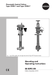
1
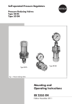
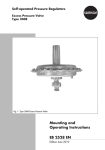
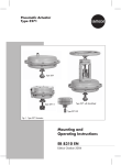
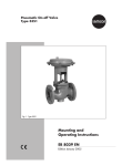
V2001 Valve Series Globe Valve for Heat Transfer Oil Type 3531 Fig. 1 ⋅ Type 3531 Valve with mounted rod-type yoke (partial view) Mounting and operating instructions EB 8131/8132 EN Edition April 2003 Contents Page Contents 1. 1.2 Design and principle of operation . . . . . . . . . . . . . . . . . . . . . . 4 Technical data . . . . . . . . . . . . . . . . . . . . . . . . . . . . . . . . 6 2. 2.1 2.2 Installation . . . . . . . . . . . . . . . . . . . . . . . . . . . . . . . . . 7 Mounting position . . . . . . . . . . . . . . . . . . . . . . . . . . . . . . 7 Strainer, bypass . . . . . . . . . . . . . . . . . . . . . . . . . . . . . . . 7 3. Operation . . . . . . . . . . . . . . . . . . . . . . . . . . . . . . . . . . 7 4. 4.1 4.2 Maintenance replacing parts . . . . . . . . . . . . . . . . . . . . . . . . 7 Replacing the metal bellows . . . . . . . . . . . . . . . . . . . . . . . . . 8 Replacing the seat and plug . . . . . . . . . . . . . . . . . . . . . . . . . 9 . . . . . . . . . . . . . . . . . . . . . . . . . . 10 5. Description of nameplate 6. Dimensions in mm . . . . . . . . . . . . . . . . . . . . . . . . . . . . . . 11 7. Customer inquiries 2 EB 8131/8132 EN . . . . . . . . . . . . . . . . . . . . . . . . . . . . . 11 General safety instructions General safety instructions The control valve must be mounted, started up and serviced by fully trained and qualified personnel only. Make sure employees or third persons are not exposed to any danger. All safety instructions and warnings in these instructions, particularly those concerning installation, start-up and maintenance, must be strictly observed. The control valve fulfills the requirements of the European Pressure Equipment Directive 97/23/EC. Valves with a CE marking have a declaration of con formity that includes information on the applied conformity assessment proce dure. The declaration of conformity can be viewed and downloaded on the In ternet at http://www.samson.de. For appropriate operation, make sure that the control valve is only used in ap plications where the operating pressure and temperatures do not exceed the operating values based on the valve sizing data submitted in the order. Note that the manufacturer does not assume any responsibility for damage caused by external forces or any other external influences. Any hazards which could be caused in the control valve by the process me dium, operating pressure, control signal or moving parts are to be prevented by means of appropriate measures. Proper shipping and appropriate storage are assumed. Caution For installation and maintenance work on the control valve, make sure the relevant section of the plant is depressurized and, depending on the process medium used, drained as well. Depending on the application, cool down or heat the valve to ambient temperature prior to starting any work on the valve. When working on the valve, make sure that the supply lines for the air supply as well as the control signals are disconnected or locked to prevent any ha zards that could be caused by moving valve parts. Special care is needed when the actuator springs of a pneumatic control valve are pretensioned. These actuators are labeled correspondingly and can also be identified by three long bolts at the bottom of the actuator. Prior to starting any work on the valve, you must relieve the compression from these preten sioned springs. EB 8131/8132 EN 3 Design and principle of operation 1. Design and principle of operation The Type 3531 Globe Valve is based on the modular design principle and can be combined with a pneumatic or electric actuator as follows: Control valve V2001-P V2001-PA V2001-IP V2001-E1 V2001-E3 Pneumatic Electropneumatic Electric Actuator type 3372-01xx 2780-2 3372-03xx 5824-30 3374 The process medium flows through the valve in the direction indicated by the arrow. The position of the valve plug (3) changes in response to changes of the control signal acting on the actuator. The plug stem is sealed by means of a metal bellows and an additional packing (4.2), and connects to the actuator stem (8.1) via the stem connector (7). 4 EB 8131/8132 EN Legend for Fig. 2 1 1.1 1.2 2 3 4 4.1 4.2 4.3 4.4 5 5.1 5.2 5.3 5.4 6 6.1 6.2 6.3 6.4 7 8.1 8.2 9 10 11 12 13 14 15 X Valve body Nut Gasket Seat Valve plug Guide bushing Bushing Packing Washer Spring (DN 65/80) Bellows assembly with plug stem and metal bellows Coupling nut Bellows housing Sealing ring Flange Plug stem Stem connector nut Lock nut Screw Washer Stem connector Actuator stem Rod-type yoke Nut Washer Spring Washer Bushing Cap Guide Position for open-end wrench Design and principle of operation DN 32 to 50 6.1 6.2 4 4.1 DN 15 to 25 8.2 9 7 8.1 4.2 4.3 5 5.1 DN 65/80 4 4.2 4.4 4.3 5.3 X 5 5 5.2 6 1.1 X 6 14 5.4 1.2 15 X 3 6.3 6.4 2 1 10 11 12 13 14 3 2 6.3 6.4 Fig. 2 ⋅ Sectional drawings EB 8131/8132 EN 5 Design and principle of operation 1.2 Technical data Valve DN 15 to 80 ANSI 1/2" to 3" PN 25 Class 150/300 Type B1 acc. to EN 1092-1, Ra 3.2-12.5µm Groove type D acc. to EN 1092-2 Raised face Nominal pressure Type of connection Flanges Seat/plug seal Metal IV (0.01 % K85) Leakage rate acc. to IEC 534-4 Characteristic Equal percentage Rangeability 50 : 1 Temperature range 10 ( 70*) to 220 °C DN K85 values m!/h C8 values Seat diameter mm 15 1/2" 20 3/4" 1.6 ⋅ 4 2⋅5 9.5 ⋅ 14 15 to 430 °F 25 1" 32 40 11/2" 50 2" 65 2 1/2" 80 3" 2.5 ⋅ 6.3 4 ⋅ 10 16 25 35 50 80 3 ⋅ 7.5 5 ⋅ 12 30 40 60 94 14 ⋅ 19 14 ⋅ 24 40 65 Materials Valve body Bonnet A216 WBC S235JR DN 15 to 25: 1.4305 ⋅ DN 32 to 80: 1.4104 1.4305 Seat Plug Metal bellows Packing Body gasket * On request 6 Spheroidal graphite iron/cast steel EB 8131/8132 EN 1.4571 PTFE Graphite on metal core Installation 2. Installation 4. Maintenance replacing parts Valve and actuator are assembled by the manufacturer. For more details on the actuator used, please refer to the corresponding mounting and operating instructions. The control valve is subject to wear and tear, especially at the seat, plug, metal bellows and packing box. Depending on the application conditions that prevail, the valve must be inspected at appropriately scheduled intervals to prevent any problems before they occur. If external leakage occurs, the metal bellows or packing box may be damaged. If the valve does not seal properly, this may be because tight shut-off is prevented by dirt or other foreign particles present between the seat and plug or due to a damaged seating surface. It is recommended that the parts be removed, thoroughly cleaned and replaced as necessary. 2.1 Mounting position The valve can be mounted in any position. However, you are required to strictly observe the limitations inherent to the used actuator type. CAUTION! The valve must be installed free of stress and free of excessive vibrations. If necessary, support the pipelines near the connections. Do not install supports on the valve or on the actuator. Thoroughly flush the pipeline prior to installation of the valve. 2.2 Strainer, bypass We recommend that you install a SAMSON Type 2 Strainer upstream of the valve. In addition to a bypass line, shut-off valves should be installed both upstream of the strainer and downstream of the control valve so that the plant need not be shut down for maintenance routines. 3. Operation Operating instructions depend on the actuator used. Please refer to the mounting and operating instructions for the corresponding actuator. CAUTION! If you intend carrying out maintenance work on the valve, first depressurize the relevant plant section and, depending on the process medium, drain it as well. Let the plant section cool down to reach ambient temperature, if necessary. Prior to starting any work, disconnect the electric or pneumatic control signal for the actuator. On pneumatic actuators, additionally remove the signal pressure line. As the process medium cannot drain completely out of the valve, be aware that some of the process medium could still be trapped in the valve. We recommend that you remove the valve from the pipeline. EB 8131/8132 EN 7 Maintenance replacing parts Note! The tightening torques and special tools re quired for installing and removing the seat are listed in the table on page 9. Important! Prior to carrying out any repairs, always separate the actuator from the valve by re moving the stem connector clamps (7) and the nut (9). Then lift the actuator off the valve. 4.1 Replacing the metal bellows Leakage occurring at the packing box is due to a damaged metal bellows. The complete bellows assembly as well as the packing (4.2) must be replaced as described below. It is recommended that the sealing ring (5.3) at the top of the bellows housing and the gasket (1.2) at the bottom of the bellows housing be replaced, too. Disassembly: 1. With nominal sizes DN 15 to 50, unscrew the stem connector nut (6.1) and lock nut (6.2). 2. First unscrew the coupling nut (5.1). Next, remove the nuts (1.1). After that, lift and remove the flange (5.4). Then remove the complete bonnet from the valve body. 3. Securely hold the flattened plug stem end by the flats (x) using an open-end wrench (width across flats SW 10 for DN 15 to 50 and SW 13 for DN 65/80) while unthreading the screw (6.3). 4. First remove the valve plug (3). Then remove the guide (15) with nominal sizes DN 15 to 25, the cap (14) with 8 EB 8131/8132 EN DN 32 to 50 and the cap (14), bushing (13), washer (12), spring (11) and washer (10) with DN 65/80. Pull the bellows assembly (5) out of the bellows housing (5.2) and remove the sealing ring (5.3). 5. Clean all parts thoroughly and check them for signs of damage. Replace the bellows assembly consisting of the plug stem, the metal bellows and the packing. Reassembly: 1. Apply lubricant (order no. 8150-0119) to the sealing ring (5.3) and the threaded part of the bellows housing, then place the sealing ring onto the bellows housing. Insert the bellows assembly (5) with the plug stem into the bellows housing and slide the flange (5.4) over the bellows housing. Tighten the coupling nut (5.1) finger tight only. 2. With nominal sizes DN 15 to 50, slide the guide (15) or cap (14) onto the plug stem and with nominal sizes 65/80, slide the washer (10), spring (11), washer (12), bushing (13) and cap (14) onto the plug stem. Apply lubricant (order no. 8150-0119) to the screw thread, place the washer (6.4) and valve plug (3) on the screw (6.3) and firmly tighten the screw into the plug stem. CAUTION! In doing so, use an open-end wrench on the flattened end of the plug stem (X) to hold the stem in place and to prevent the metal bellows from being rotated. Maintenance replacing parts 3. Place the gasket (1.2) onto the valve body. Then insert the complete bonnet into the valve body. 4. Align the flange (5.4) and tighten the nuts (1.1) according to the tightening torques specified in the table on the right. 5. Tighten the coupling nut (5.1) according to the tightening torques specified in the table on the right. 6. With nominal sizes DN 15 to 50, thread the lock nut (6.2) and stem connector nut (6.1) onto the upper end of the plug stem until there is a 50-mm gap between the upper edge of the bellows assembly (5) and the upper edge of the stem connector nut (6.1) in the closed valve position. DN Seat wrench order no. 15 to 25 1/2 to 1" 32 to 50 11/2 to 2" 65 to 80 21/2 to 3" 9932-3330 1280-3009 9110-2467 Tightening torque ±10% Seat thread M32 x 1.5 120 Nm Coupling nut (5.1) Body nuts (1.1) M58 x 1.5 500 Nm M90 x 1.5 1050 Nm 80 Nm M10 10 Nm M12 30 Nm M16 90 Nm 4.2 Replacing the seat and plug When replacing the seat and/or plug, it is recommended that the sealing ring (5.3) at the top of the bellows housing and the gasket (1.2) at the bottom of the bellows housing be additionally replaced. To replace the plug (3), proceed as follows: Follow the steps as described in chapter 4.1, except replace the old plug with a new one. To replace the seat (2), proceed as follows: Follow the steps as described in chapter 4.1, except replace the old seat with a new one. To unthread the seat (2), use an appropriate seat wrench (refer to the table on the right). Lubricate the thread and sealing cone of the new seat (lubricant order no. 8150-0119) and screw in. EB 8131/8132 EN 9 Description of nameplate 5. Description of nameplate 2 1 3 SAMSON No DIN version SAMSON psi N ∆p ANSI version Fig. 3 ⋅ Nameplate 10 EB 8131/8132 EN Kvs bar T ˚C 11 9 8 2 ∆p PN bar DN 3 1 Made in Germany 12 9 Size Cl Cv ˚F 10 5 4 No psi T 1 2 3 4 5 8 9 11 12 5 4 Made in Germany 11 12 Valve type Model number Model index Order number or date K85 value Nominal size Nominal pressure Permissible temperature (°C) Body material For ANSI version 1 Valve type 2 Model number 3 Model index 4 Order number or date 5 Nominal size 9 Permissible temperature (°F) 10 Body material 11 C8 value (K85 x 1.17) 12 ANSI class (nominal pressure) Customer inquiries 6. Dimensions in mm DIN DN (mm) L mm H mm 15 20 25 130 150 160 284 32 40 50 180 200 230 296 65 80 290 310 ANSI L (in) Class DN (in) 150 300 1/2" 7.50 7.62 1" 396 3/4" 7.25 50 (1.96) H H (in) 11.2 7.75 1 1/2" 8.75 9.25 2" 10.00 10.50 2 1/2" 10.90 11.50 3" 11.75 12.50 11.65 L 15.6 Max. operating pressure 25 bar 7. Customer inquiries Should you have any inquiries, please submit the following details: Type designation and order no. (see nameplate) Product no., nominal size and valve version Pressure and temperature of process medium Flow rate in m3/h Bench range (signal pressure range), e.g. 1.4 to 2.3 bar, when a pneumatic actuator is used Installation drawing EB 8131/8132 EN 11 EB 8131/8132 EN S/Z 2003-04 SAMSON AG ⋅ MESS- UND REGELTECHNIK Weismüllerstraße 3 ⋅ 60314 Frankfurt am Main ⋅ Germany Phone: +49 69 4009-0 ⋅ Fax: +49 69 4009-1507 Internet: http://www.samson.de