1
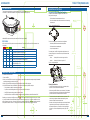
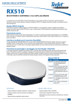
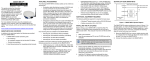
U S ER GUI DE
RX510
L1/L2 GPS+GLONASS RECEIVER AND ANTENNA
Thank you for choosing TeeJet Technologies’ RX510 as your GPS solution. The information and instructions provided are available to enhance
or expand the performance of the RX510. Contact your local dealer for more information or visit www.teejet.com.
Integrated GNSS Design
The RX510 provides an integrated L1/L2 GPS+GLONASS receiver and antenna in a single compact enclosure. Designed to meet or exceed
stringent MIL-STD-810G specifications, the RX510’s rugged metal housing ensures high performance even in the most challenging work
environments.
Precision Performance
The RX510 features 14 channels for each of L1 and L2 GPS and 12 channels for each of L1 and L2 GLONASS code and phase tracking. An
additional two channels are dedicated for Satellite-Based Augmentation System (SBAS: WAAS, EGNOS and MSAS) signals as well as one
channel for L-band (OmniStar).
Multiple Interfaces Deliver Maximum Flexibility
Three NMEA 0183 compatible RS-232 serial ports, one NMEA2000 compatible CAN port and built-in Bluetooth ensure the RX510 delivers
maximum flexibility. An Emulated Radar ground speed output, a one pulse per second output (1 PPS) and an event mark input are also
provided. Three daylight readable status LEDs simplify infield diagnoses.
Smooth, Pass-to-Pass Accuracy with ClearPath® Technology
ClearPath technology is integrated into every RX510 antenna. ClearPath uses the very accurate carrier phase calculations to provide ultra
smooth positions and excellent pass-to-pass accuracy for agricultural applications. ClearPath functions autonomously and with most available
corrections services. It will also bridge through short periods of poor satellite availability. ClearPath’s steady, smooth output is especially well
suited for manual guidance and autosteer installations.
RX510 Options
Part #
Description
90-02755 Kit, RX510 GPS Receiver,
GPS/GLONASS/WAAS/
ClearPath
78-50192 RX510,GPS Receiver, GPS/
GLONASS/WAAS/ClearPath
90-02703 Kit, RX510 GPS Receiver,
GPS/GLONASS/OmniStar
XP/HP
78-50184 RX510 GPS Receiver, GPS/
GLONASS/OmniStar XP/HP
90-02744 Kit, Quick Release Mount for
RX510
45-05808 Cable, Antenna, Power to
Serial w/Pins
BENEFITS
F E AT U R E S
• Scalable dual-constellation, dual-frequency performance
• GPS and GLONASS satellite capability
• Smooth, consistent positions for pass-to-pass accuracy
• ClearPath® and AdVance® RTK positioning
• Rugged design for on-machine applications
• Robust power handling for 12 V to 24 V vehicle power
www.teejet.com
U SER G UI DE
TE E J E T TECHNOLOGIES
GETTING STARTED
This guide provides the information you need to set up and begin using your new RX510,
a combined L1+L2 GNSS receiver and antenna, with L-band support and Emulated Radar (ER) output.
MOUNTING INSTRUCTIONS
Intermediate Mounting Plate Template
A template for the intermediate mounting plate has been drawn in the
background of this user guide.
• Red lines indicate holes where attachement will occur.
9.2 in
234 mm
• Green lines indicate the outline of the mount and other holes for attaching
the release plate.
0.402 in (10.20 mm)
Opening
Figure 1-1: Intermediate Mounting Plate
3.5 in
89 mm
9.2 in
234 mm
Additional NMEA outputs are available, please contact TeeJet Technical Support for details.
RX510 LEDs
LEDs on the front of the RX510 provide basic receiver status information. The operation of the LEDs on the RX510 is summarized in the
following table:
Red
Yellow
Green
Condition
Off
Off
Off
Power is not available. (Red indicator may also not be lit if a boot failure has occurred.)
On
Off
Off
Power available but no satellites are being tracked
On
Flashing Off
Tracking at least one satellite but not a valid position
On
On
Off
Position valid in basic autonomous mode
On
On
Flashing SBAS tracking, but not enough data for enhanced solution
On
On
On
On
Flashing Flashing Fixed position with bad integrity
Position valid in an enhanced accuracy mode* (WAAS/EGNOS/MSAS/DGPS,
OmniSTAR VBS/XP/HP, or RTK)
The universal mounting plate can be used in several configurations:
• Stand-alone plate that is hard-mounted onto the implement
• Hard-mounted onto an intermediate plate
• As part of the quick-release kit
The mounting holes in the RX510 will align with the dimple locations in the
universal mounting plate. You can use Metric or Imperial Countersunk head
bolts as follows:
8.217 in
(208.70 mm)
• Metric.............. Quantity 4 M6x 1.0mm bolts no longer than 15mm
• Imperial........... Quantity 4 1/4-20 bolts no longer than 1/2"
Figure 1-2: Complete Mounting Kit
Quick Release Latch
Universal Mounting Plate
R2.01 in
(5.10 mm) TYP.
* When acting as a reference receiver, all lights on solid indicates a good fixed position.
OMNISTAR® SUBSCRIPTION
To subscribe to OmniSTAR XP or HP:
1. Power on the RX510.
2. Before you call OmniSTAR, find a clear view of the sky towards the equator that will be available before and approximately 45 minutes after
completing the subscription purchase from OmniSTAR.
3. Before you call OmniSTAR, find the 6-digit OmniSTAR Serial Number (OSN) on the RX510 shipping box.
4. Call OmniSTAR Customer Service (1-888-883-8476 in North, Central and South America) to start the subscription.
• Pricing information is available at: http://omnistar.com/pricing.html
• If you intend to use GLONASS together with GPS, you will need to specify the G2 subscription.
• OmniSTAR will require a credit card number for subscription charges.
• OmniSTAR will ask for the OmniSTAR Serial Number, and when they ask for the Manufacturer, tell them "Manufacturer ID 007"
Depending on your location, the OmniSTAR service you subscribed to, and the satellite information reported by the device you are connected
to, you may see the Station ID number (PRN number) change to somewhere in the range of 1000 to 1021 once the subscription is received
and the convergence process begins. It may take up to 45 minutes for complete OmniSTAR XP/HP convergence to take place and the GGA
Quality Indicator to transition to a value of "5", during which time the Station ID number (PRN number) may change several times.
98-01405 R0 US
Intermediate
Mounting Plate
Mounting Considerations
• Choose a location that has a clear view of the sky so that each satellite
above the horizon can be tracked without obstruction.
3.937 in
(100.00 mm)
• When mounting the RX510 Receiver, a space of at least 6″ (15 cm) between
the receiver and any bend in the cable is required. Any length shorter than 6″
puts undue stress on the cable and the enclosure for the RX510.
• The receiver should not be mounted where water can pool around it. The
receiver housing is designed to withstand rain and splashing, but not
submersion in liquids for sustained periods of time.
• Mount the receiver above all other metal objects to avoid multipath. Satellite
signals received by the GPS receiver by a reflection from an object can
decrease positioning accuracy. For example, roof racks, large headlight
enclosures, etc., can cause multipath that may result in a jump in GPS
position.
0.492 in
(12.5 mm)
TYP.
1.969 in
(50.00 mm)
www.teejet.com
U S ER G U IDE
SPECIFICATIONS
Performance
Channel Configuration
14 GPS L1, 14 GPS L2
12 GLONASS L1, 12 GLONASS L2 (optional)
2 SBAS1
1 L-band
Horizontal Position Accuracy (RMS)2
Autonomous (L1).......................................... 1.5 m
Autonomous (L1/L2)..................................... 1.2 m
SBAS ........................................................... 0.6 m
CDGPS ........................................................ 0.6 m
DGPS .......................................................... 0.4 m
OmniSTAR VBS .......................................... 0.6 m
OmniSTAR XP ........................................... 0.15 m
OmniSTAR HP 0.1m RT-20®3 (optional) ...... 0.2 m
RT-2™3 (optional) ...............................1 cm+1ppm
Measurement Precision
GPS GLONASS
L1 C/A Code.........................4.0 cm .......15.0 cm
L1 Carrier Phase..................0.5 mm ........1.5 mm
L2 P(Y) Code........................8.0 cm .........8.0 cm
L2 Carrier Phase..................1.0 mm ........1.5 mm
Maximum Data Rate
Measurements ..................1Hz, 5Hz, 10Hz, 20Hz4
Position .............................1Hz, 5Hz, 10Hz, 20Hz4
Time to First Fix
Cold Start5 ......................................................65 s
Hot Start6 ........................................................35 s
Signal Reacquisition
L1 .................................................... 0.5 s (typical)
L2 .................................................... 1.0 s (typical)
Accuracy
Time Accuracy7.................................... 20 ns RMS
Velocity Accuracy8 ..........................0.03 m/s RMS
Physical and Electrical
Dimensions ........................... 9.2″ x 9.2″ x 3.5″ (H)
............................233 mm x 232 mm x 89 mm (H)
Weight .......................................... 4.19 lbs, 1.9 kg
Input Voltage .................................+9 to +36 VDC
Power Consumption .......................3.7 W (typical)
Connector............................. 23-pin Tyco Ampseal
Mounting...............1/4 NC and M6 mounting holes
Communication Ports
3 RS-232 serial ports
One port configurable to RS-422
Default NMEA messages
Com Port 1............................ 19200 baud rate,
5 Hz GGA, ZDA 5 sec.
1 CAN Bus NMEA 20008
1 Bluetooth
Emulated Radar
Default operation frequency.......36.11 Hz/km/h
1 PPS
Event mark input
Environmental
Temperature
Operating ..........-40°F to +158°F, -40°C to +70°C
Storage .............-67°F to +194°F, -55°C to +90°C
Humidity .............................95% non-condensing
Vibration
Random ........................................ MIL-STD-202G
Sinusoidal ........................................ ASAE EP455
Shock ................................. MIL-STD-810G, 516.6
Immersion .......................... MIL-STD-810G, 512.5
Blowing Rain ...................... MIL-STD-810G, 506.5
Water Jets................................... IEC 60529 IPX6
Object Ingress and Immersion
..................................................... IEC 60529 IP67
Aggravated Cycle .............. MIL-STD-810G, 507.5
Compliance
Emissions......FCC, CE, Industry Canada, BT SIG
Immunity .......................................................... CE
Vehicular Standards
ISO 7637: Compliance ensures product’s ability to
operate through vehicular electrical system surges
(including inductive load switching transients,
crank cycle and load dump)
ISO 15003: Compliance ensures product’s ability
to withstand vehicular electrical system abnormal
conditions (short circuits to battery or ground,
overvoltage reverse polarity and abnormal power
voltage)
1 Satellite Based Augmentation Systems (SBAS) include WAAS (North America), EGNOS (Europe) and MSAS (Japan).
2 Typical values. Performance specifications subject to GPS system characteristics, US DOD operational degradation, ionospheric
and tropospheric conditions, satellite geometry, baseline length, multipath effects and the presence of intentional or unintentional
interference sources.
3 Expected accuracy after convergence. RT-20 and RT-2 are independent of ClearPath.
4 Contact TeeJet Technologies for 20Hz operation.
5 Typical value. No almanac or ephemerides and no approximate position or time.
6 Typical value. Almanac and recent ephemerides saved and approximate time entered.
7 Relative time accuracy does not include biases due to RF or antenna delay.
8 Export licensing restricts operation to a maximum velocity of 515 meters per second.
9 Fixed CAN messages in firmware.
TeeJet Technologies
1801 Business Park Drive
Springfield, Illinois 62703 USA
Tel: (217) 747-0235 • Fax: (217) 753-8426
www.teejet.com
98-01405 R0 US English
© TeeJet Technologies 2011
Warranty
1 Year From Date of Purchase
Electrical Connection
Connector’s Pin-outs
1............................................................... Power +
2................................................................ Power 3.................................................................CAN1 4................................................................CAN1 +
5.................................................................. TXD 2
6..................................................................RXD 2
7.....................................................TXD1/TXD1 +*
8.........................................RTS1/AUXTX/TXD1 -*
9.................................................. Signal Ground 2
10........................................................... Reserved
11............................................................ Reserved
12........................................................... Reserved
13........................................................... Reserved
14.................................................Chassis Ground
15................................................ Signal Ground 1
16.................................................................... MKI
17................................................................... PPS
18..................................................................... ER
19................................................................MODE
20........................................................... Reserved
21........................................................... Reserved
22......................................CTS1/AUXRX/RXD1 -*
23...................................................RXD1/RXD! +*
* The RX510 is RS-232/RS-422-selectable through pin 19