1
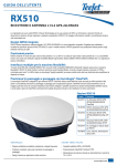
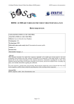
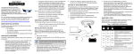
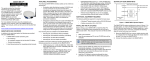
U S ER GUI DE
RX610
L1/L2 GPS+L1/L2 GLONASS RECEIVER SMART ANTENNA
with integrated cellular modem for access to wireless RTK corrections
Thank you for choosing TeeJet Technologies’ RX610 as your RTK solution. The information and instructions provided are available to enhance
or expand the performance of the RX610. Contact your local dealer for more information or visit www.teejet.com.
Integrated GNSS Design
The RX610 provides an integrated L1/L2 GPS+GLONASS receiver and antenna in a single compact enclosure. Designed to meet or
exceed stringent MIL-STD-810G specifications, the RX610’s rugged metal housing ensures high performance even in the most challenging
work environments.
Integrated Cellular Modem
The RX610 comes equipped with an embedded CDMA (Carrier Division Multiple Access) or GPRS/HSDPA/GSM (General Packet
Radio Service / High Speed Downlink Packet Access / Global System for Mobile) radio to allow NTRIP data to be received
over a cellular network. The CDMA radio is Verizon Wireless carrier approved and the GPRS/HSDPA/GSM radio is PTCRB and
GFC certified to ensure optimal operation. An external cellular connector with optional high efficiency antenna provides robust
connections even in poor coverage areas.
Precision Performance
The RX610 features 14 channels for each of L1 and L2 GPS and 12 channels for each of L1 and L2 GLONASS code and phase
tracking. An additional two channels are dedicated for Satellite-Based Augmentation System (WAAS, EGNOS and MSAS)
signals as well as one channel for L-band (OmniSTAR®).
Multiple Interfaces Deliver Maximum Flexibility
Two NMEA 0183 compatible RS-232 serial ports, one NMEA2000 compatible
CAN port and built-in Bluetooth ensure the RX610 delivers maximum
flexibility. An Emulated Radar ground speed output, a one pulse per
second output (1 PPS) and an event mark input are also provided.
Three daylight readable status LEDs simplify infield diagnoses.
Smooth, Pass-to-Pass Accuracy with
ClearPath® Technology
ClearPath technology is integrated into every RX610 antenna.
ClearPath uses the very accurate carrier phase calculations to
provide ultra smooth positions and excellent pass-to-pass accuracy
for agricultural applications. ClearPath functions autonomously and
with most available corrections services. It will also bridge through short
periods of poor satellite availability. ClearPath’s steady, smooth output is
especially well suited for manual guidance and autosteer installations.
CDMA Whip Antenna shown
BENEFITS
F E AT U R E S
• Scalable dual-constellation, dual-frequency performance
• GPS and GLONASS satellite capability
• Smooth, consistent positions for pass-to-pass accuracy
• ClearPath® and AdVance® RTK positioning
• Rugged design for on-machine applications
• Robust power handling for 12 V to 24 V vehicle power
• OmniSTAR® compatibility
• Integrated cellular modem for access to wireless RTK Network
www.teejet.com
U SER G UI DE
CORS NETWORK RTK / NTRIP CORRECTIONS VIA CELLULAR NETWORK
Setup and usage of the NTRIP feature on TeeJet RX610 systems when paired with TeeJet Matrix PRO.
Description
DEFINITIONS
• NTRIP allows the RX610 receiver/smart antenna to receive RTK
corrections from local CORS or RTK networks, where available.
CORS (Continuously Operating Reference Station)/
Network RTK
• The cellular modem built into the RX610 is used to access the Internet,
from which the RTK correction data is sourced.
A series of base stations spread across a given geographic
region (such as an entire state/county) that are networked
via a centralized computer and which broadcast RTK
correction data over the Internet. CORS networks may be
publicly or privately owned/operated and may offer a free
signal or require an annual subscription fee. By accessing
a CORS network via a cellular connection, the end-user
eliminates the need to own a base station.
Benefits
Using NTRIP allows the RX610 to generate RTK precision GPS coordinates
without using a local base station.
Limitations
NTRIP can only be used when a good connection to the Internet is present.
Internet connections supported through the internal modem built into the
RX610 are CDMA (Verizon) or GPRS/HSDPA/GSM (AT&T, T-Mobile). A
Data Plan through a local cellular carrier must be purchased for the RX610
in order for the system to operate on CORS networks.
NTRIP (Networked Transportation of RTCM via Internet
Protocol)
An internet based application that makes the RTCM
Correction data from the CORS stations available to
anyone with an internet connection and the appropriate
log on credentials to the NTRIP server. Typically uses a
cellular link to connect the rover to the internet and the
NTRIP server.
Required Items
• In order to use NTRIP, it is necessary to be within the bounds of the
network being used. Only NTRIP streams providing CMR, CMR+, or
RTCM 3 format corrections are supported. GLONASS is only supported
with RTCM 3 format when available through RTK provider.
• Data Plan obtained from cellular provider for integrated modem in
RX610. 5GB per month rate plans are recommended for network RTK.
Network RTK
COMMON
SATELLITE
COMMON
SATELLITE
NETWORK
SERVER
INTERNET
REFERENCE
STATION
TEEJET
RX610
REFERENCE
STATION
REFERENCE
STATION
REFERENCE
STATION
2
98-01411 R0 US
MASTER
STATION
T EE JE T T EC H N OLO G IE S
GETTING STARTED
This guide provides the information you need to set up and begin using your new RX610.
0.402 in (10.20 mm)
Opening
9.2 in
234 mm
11.125 in
280 mm
3.5 in
89 mm
12 in
300 mm
9.2 in
234 mm
3.25 in
83 mm
2.25 in
57 mm
CDMA Whip Antenna
12 in
300 mm
3.25 in
83 mm
GPRS/HSDPA/GSM Antenna
RX610 LEDs
8.217 in
(208.70 mm)
LEDs on the front of the RX610 provide basic receiver status information. The operation of
the LEDs on the RX610 is summarized in the following table:
Red
Yellow
Green
Condition
Off
Off
Off
Power is not available or there has been a hardware
failure.
On
Off
Off
Power available but no satellites are being tracked.
No cellular network connection.*
On
Flashing Off
Tracking at least one satellite but not a valid position.
No cellular network connection.
On
On
Off
Position valid in basic autonomous mode. No cellular
network connection.
On
On
Flashing SBAS tracking, but not enough data for enhanced
solution. Connected to cellular network but not
receiving RTK corrections.
On
On
On
On
R2.01 in
(5.10 mm) TYP.
3.937 in
(100.00 mm)
Position valid in an enhanced accuracy mode**
(WAAS/EGNOS/MSAS/DGPS, OmniSTAR VBS/
XP/HP, or RTK). Connected to cellular network and
receiving RTK corrections.
Flashing Flashing Fixed position with bad integrity. Connected to
cellular network but not receiving RTK corrections.
* If the RX610 NTRIP client is not active, LED operation will not reflect the status of the cellular network.
** When acting as a reference receiver, all lights on solid indicates a good fixed position.
0.492 in
(12.5 mm)
TYP.
1.969 in
(50.00 mm)
www.teejet.com
3
U SER G UI DE
MOUNTING PLATE INSTALLATION INSTRUCTIONS
Intermediate Mounting Plate Template
A template for the intermediate mounting plate (included in the optional
Quick Release Mounting kit part number 90-02744) has been drawn in the
background of this user guide (pages 3 and 6).
Figure 1-1: Intermediate Mounting Plate
• Red lines indicate holes where attachment will occur.
• Green lines indicate the outline of the mount and other holes for
attaching the release plate.
The universal mounting plate can be used in several configurations:
• Stand-alone plate that is hard-mounted onto the implement
• Hard-mounted onto an intermediate plate
• As part of the quick-release kit
The mounting holes in the RX610 will align with the dimple locations in
the universal mounting plate. You can use Metric or Imperial Countersunk
head bolts as follows:
Figure 1-2: Complete Mounting Kit
Quick Release Latch
Universal Mounting Plate
• Metric.............. Quantity 4 M6x 1.0mm bolts no longer than 15mm
• Imperial........... Quantity 4 1/4-20 bolts no longer than 1/2"
Mounting Considerations
• Choose a location that has a clear view of the sky so that each satellite
above the horizon can be tracked without obstruction.
Intermediate
Mounting Plate
• RX610 cable is typically connected near the Quick Release Latch,
usually towards the back of the cab.
• The accompanying cellular antenna should be mounted at least
12″ / 30 cm from the RX610 receiver on a metal surface.
• When mounting the RX610 Receiver, a space of at least 6″ / 15 cm
between the receiver and any bend in the cable is required. Any
length shorter than 6″ / 15 cm puts undue stress on the cable and the
enclosure for the RX610.
• The receiver should not be mounted where water can pool around it.
The receiver housing is designed to withstand rain and splashing, but
not submersion in liquids for sustained periods of time.
• Mount the receiver above all other metal objects to avoid multipath.
Satellite signals received by the GPS receiver by a reflection from an
object can decrease positioning accuracy. For example, roof racks, large
headlight enclosures, etc., can cause multipath that may result in a jump
in GPS position.
ANTENNA INSTALLATION
Mounting Considerations
• Be sure to connect the correct antenna to the receiver.
• Do not connect a CDMA whip antenna to a GPRS/HSDPA/GSM RX610 receiver.
• Do not connect a GPRS/HSDPA/GSM antenna to a CDMA RX610 receiver.
• Mount the cellular antenna at least 12″ / 30 cm from the RX610 receiver.
• In most installations, the cellular antenna should be mounted on top of the cab as far forward as possible on a metal surface of at least 4″
square. If the mounting surface is not metal, use the included metal plate and Velcro® to create a metal base for the antenna.
4
98-01411 R0 US
T EE JE T T EC H N OLO G IE S
CABLE CONNECTIONS
The following diagram is reflective of a typical RX610 with Matrix Pro and FieldPilot configuration. Due to the variety of possible configurations,
this should be used for reference purposes only.
Figure 1-3: System Diagram with Matrix Pro and FieldPilot
Matrix Pro 570G
Matrix Pro 840G
Power/DATA
45-05626
RX610 GPS Receiver, RTK
RS-232
RS-232
45-05808
Smart Antenna Cable
POWER IN
Power/CAN/Data Cable
(included with FieldPilot
and BoomPilot kits)
CAN
Steering Control
Module (SCM)
SCM Power I/O
45-07703
DC: xx/xx
CAN
Valve Output
SCM COM 2
GPS In
COM 1
POWER IN
GPS Power
Co
nn
(+ ecto
12
v) to
Remote
Engage/Disengage
Seat Sensor
FieldPilot Interface
78-08072
DC: xx/xx
Steering
Wheel Sense
45-05381
DC: xx/xx
Steering Valve
Engage / Disengage
32-04020
DC: xx/xx
Power
SCM Harness
RX610 Options
45-10103
DC: xx/xx
Part #
Description
90-02791
Kit: RX610 GPS RTK Receiver – CDMA, North America;
Cable; Antenna
78-50193 RX610,GPS Receiver – CDMA, North America
78-50196 CDMA Whip Antenna
78-50197 CDMA Whip Antenna Base
90-02792
Kit: RX610 GPS RTK Receiver – GPRS/HSDPA/GSM, North
America; Cable; Antenna
90-02793
Kit: RX610 GPS RTK Receiver – GPRS/HSDPA/GSM,
Europe; Cable; Antenna
78-50194 RX610 GPS Receiver – GPRS/HSDPA/GSM, North America
78-50195 RX610 GPS Receiver – GPRS/HSDPA/GSM, Europe
78-50198 GPRS/HSDPA/GSM Antenna
78-50199 GPRS/HSDPA/GSM Antenna Base
90-02744
Kit: Quick Release Mount for RX510/RX610
45-05808
Cable – Antenna, Power to Serial w/Pins
www.teejet.com
5
U SER G UI DE
ACTIVE CELLULAR DATA PLAN CONFIRMATION
TeeJet Technologies will provide the RX610 pre-configured with only the cellular data plan to be purchased by the end-user. In order to preconfigure the RX610, the items listed on bulletin 98-01410 (obtained from dealer) were required before contacting TeeJet Technologies to place
your order: If these requested items have changed or were provided with a mistake, please contact your local dealer or TeeJet Technologies for
further assistance.
SIM CARD INSTALLATION
SIM Card Installation is for GPRS/HSDPA/GSM units only. A SIM card is not used with the CDMA unit.
To install the SIM Card:
1. Remove the SIM cover by loosening the two screws that secure the cover.
NOTE: When you are replacing the SIM cover, make sure it is installed straight or you may inadvertently cause the SIM card to eject.
2. Install the SIM following the orientation shown on the SIM cover (notch up and in, as shown).
The SIM connector is a push -in/push-out type. If the SIM is correctly installed, its outside edge will be essentially flush with the surrounding
enclosure metal surface.
NOTE: To remove the SIM push it in slightly and it should then be partially ejected by the SIM holder.
The modem will not work if the SIM is in the partially ejected “ready for removal” position. Ensure the SIM door is properly aligned, then
secure it in place.
WARNING: Secure the SIM cover to the base using a flat-head screwdriver. Screws should be torqued to 4-6 in-lb / 22-34 cm-kg, to ensure the
unit does not leak.
6
98-01411 R0 US
T EE JE T T EC H N OLO G IE S
MATRIX PRO GPS SETTINGS
GPS Port Setting on Matrix Pro
Working with GPS signals such as OmniSTAR HP/XP or RTK will
require the GPS port to be set to External. GPS Port sets port
transmission to Internal or External.
1. Press CONFIGURATION side tab
2. Press GPS .
3. Press GPS Port DOWN arrow
4. Select External .
.
Quality Indicator on Matrix Pro
When the RX610 is providing RTK correction, the Quality Indicator on
the Matrix Pro should read "4".
Figure 1-5: GPS Status from Operation Screens
Mark A
-13
7.2 km/h
to access the list of options.
5. Press RETURN arrow
or CONFIGURATION side tab
return to the main Configuration screen.
to
Figure 1-4: GPS Port
Mark A
-13
Configuration
Vehicle
Implement
AutoSteer
Tilt
7.2 km/h
GGA Rate: 5 Hz
VTG Rate: 5 Hz
Num Sats: 10
Lightbar
HDOP: 1
GPS
PRN: 135
GGA Quality: 4
Video
Receiver: 1
Config->GPS
GPS Type
GPS/DGPS
GPS Port
External
GPS Status
Internal
Information
External
Figure 1-6: GPS Status from Setup Screen
Config->GPS
GPS Type
GPS/DGPS
GPS Port
Internal
GPS Status
Config->GPS
GPS Type
GPS Port
GPS Status
Information
GPS Information
GGA Rate: 5 Hz
GPS/DGPS
VTG Rate:
5 Hz
Num Sats: 10
HDOP:
1
Internal
PRN: 135
GGA Quality: 4
Receiver: 1 Information
Version:
OK
NOTE: If GPS is not available, all entries will be “Invalid”
www.teejet.com
7
U S ER G U IDE
SPECIFICATIONS
Performance
Channel Configuration
14 GPS L1, 14 GPS L2
12 GLONASS L1, 12 GLONASS L2 (optional)
2 SBAS
1 L-band
Horizontal Position Accuracy (RMS)1
Autonomous (L1).......................................... 1.5 m
Autonomous (L1/L2)..................................... 1.2 m
SBAS2........................................................... 0.6 m
CDGPS......................................................... 0.6 m
DGPS........................................................... 0.4 m
OmniSTAR VBS........................................... 0.6 m
OmniSTAR XP............................................ 0.15 m
OmniSTAR HP.............................................. 0.1 m
RT-20®3 (optional)......................................... 0.2 m
RT-2™3 (optional)................................1 cm+1ppm
Measurement Precision
GPS GLONASS
L1 C/A Code.........................4.0 cm........15.0 cm
L1 Carrier Phase..................0.5 mm.........1.5 mm
L2 P(Y) Code........................8.0 cm..........8.0 cm
L2 Carrier Phase..................1.0 mm.........1.5 mm
Maximum Data Rate
Measurements...................1Hz, 5Hz, 10Hz, 20Hz4
Position..............................1Hz, 5Hz, 10Hz, 20Hz4
Time to First Fix
Cold Start5.......................................................65 s
Hot Start6.........................................................35 s
Signal Reacquisition
L1..................................................... 0.5 s (typical)
L2..................................................... 1.0 s (typical)
Accuracy
Time Accuracy7.................................... 20 ns RMS
Velocity Accuracy8...........................0.03 m/s RMS
Physical and Electrical
Dimensions............................ 9.2″ x 9.2″ x 3.5″ (H)
............................233 mm x 233 mm x 90 mm (H)
Weight........................................... 4.63 lbs, 2.1 kg
Input Voltage..................................+9 to +36 VDC
Power Consumption........................4.5 W (typical)
Connector............................. 23-pin Tyco Ampseal
Mounting...............1/4 NC and M6 mounting holes
Communication Ports
2 RS-232 serial ports................230, 400 BPA max
One port configurable to RS-422
1 CAN Bus NMEA 20008
1 Bluetooth
1 PPS
Ground speed output
Event mark input
Environmental
Temperature
Operating...........-40°F to +149°F, -40°C to +65°C
Storage..............-40°F to +185°F, -40°C to +85°C
Humidity..............................95% non-condensing
Vibration
Random......................................... MIL-STD-202G
Sinusoidal......................................... ASAE EP455
Shock................................. MIL-STD-810G, 516.6
Immersion......................... MIL-STD-810G, 512.5
Blowing Rain..................... MIL-STD-810G, 506.5
Water Jets.................................. IEC 60529 IPX6
Object Ingress & Immersion...... IEC 60529 IP67
Aggravated Cycle............. MIL-STD-810G, 507.5
Ingress Protection Rating............................ IP67
Compliance
Emissions......FCC, CE, Industry Canada, BT SIG
Immunity & Safety............................................ CE
Vehicular Standards
ISO 7637: Compliance ensures product’s ability
to operate through vehicular electrical system
surges (including inductive load switching
transients, crank cycle and load dump)
ISO 15003: Compliance ensures product’s
ability to withstand vehicular electrical system
abnormal conditions (short circuits to battery
or ground, overvoltage reverse polarity and
abnormal power voltage)
Radios
Bluetooth................................................BT SIG
CDMA.......................................Verizon certified
GSM/GPRS/HSDPA.....PTCRB & GCF certified
Warranty
1 Year From Date of Purchase
Cellular Connectivity
CDMA Option
Dual-band....................................... 800/1900 MHz
1xRTT data..................................up to 153.6 kbps
External antenna connector
GSM/GPRS/HSDPA Option
Tri-band UMTS/HSDPA......... 850/1900/2100 MHz
Quad-band EGSM.......... 850/900/1800/1900 MHz
HSDPA.....................................................7.2 Mbps
GPRS multi-slot....................................... Class 12
EDGE multi-slot....................................... Class 12
External antenna connector
External SIM access
Electrical Connection
Connector’s Pin-outs
1............................................................... Power +
2................................................................ Power 3.................................................................CAN1 4................................................................CAN1 +
5.................................................................. TXD 2
6..................................................................RXD 2
7.....................................................TXD1/TXD1 +*
8.........................................RTS1/AUXTX/TXD1 -*
9.................................................. Signal Ground 2
10........................................................... Reserved
11............................................................ Reserved
12........................................................... Reserved
13........................................................... Reserved
14.................................................Chassis Ground
15................................................ Signal Ground 1
16.................................................................... MKI
17................................................................... PPS
18..................................................................... ER
19................................................................MODE
20........................................................... Reserved
21........................................................... Reserved
22......................................CTS1/AUXRX/RXD1 -*
23...................................................RXD1/RXD! +*
* The RX610 is RS-232/RS-422-selectable through pin 19
1 Typical values. Performance specifications subject to GPS system characteristics, US DOD operational degradation, ionospheric and tropospheric
conditions, satellite geometry, baseline length, multipath effects and the presence of intentional or unintentional interference sources.
2 Satellite Based Augmentation Systems (SBAS) include WAAS (North America), EGNOS (Europe) and MSAS (Japan).
3 Expected accuracy after convergence. RT-20 and RT-2 are independent of ClearPath.
4 Contact TeeJet Technologies for 20Hz operation.
5 Typical value. No almanac or ephemerides and no approximate position or time.
6 Typical value. Almanac and recent ephemerides saved and approximate time entered.
7 Relative time accuracy does not include biases due to RF or antenna delay.
8 Export licensing restricts operation to a maximum velocity of 515 meters per second.
TeeJet Technologies
1801 Business Park Drive
Springfield, Illinois 62703 USA
Tel: (217) 747-0235 • Fax: (217) 753-8426
www.teejet.com
98-01411 R0 US English
© TeeJet Technologies 2011