1
Pspug.book Page 255 Wednesday, November 11, 1998 1:52 PM
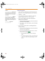
Timing characteristics
Inertial and transport delay
The simulator uses two different types of internal delay
functions when simulating the digital portion of the
circuit: inertial delay and transport delay. The application of
these concepts is embodied within the implementation of
the digital primitives within the simulator. Therefore,
they are not user-selectable.
Inertial delay
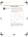
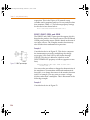
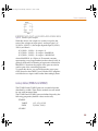
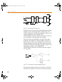
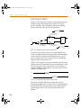
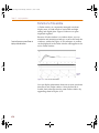
The simulation of a device may be described as the
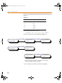
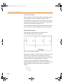
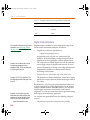
application of some stimulus (S) to a function (F) and
predicting the response (R).
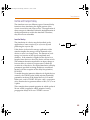
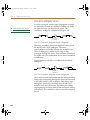
S
F
R
If this device is electrical in nature, application of the
stimulus implies that energy will be imparted to the
device to cause it to change state. The amount of such
energy is a function of the signal’s amplitude and
duration. If the stimulus is applied to the device for a
length of time that is too short, the device will not switch.
The minimum duration required for an input change to
have an effect on a device’s output state is called the
inertial delay of the device. For digital simulation, all delay
parameters specified in timing models are considered
inertial, with the exception of the delay line primitive,
DLYLINE.
To model the noise immunity behavior of digital devices
correctly, the TPWRT (pulse width rejection threshold)
parameter can be set in the digital device’s I/O model.
When pulse width ≥ TPWRT and pulse width < propagation
delay, then the device generates either a 0-R-0, 1-F-1, or an
X pulse.
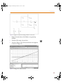
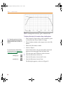
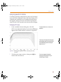
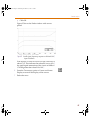
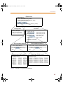
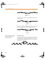
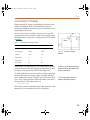
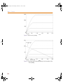
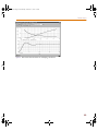
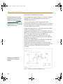
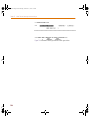
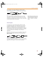
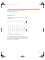
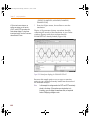
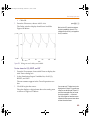
This example shows normal operation in which a pulse of
20 nsec width is applied to a BUF primitive having
propagation delays of 10 nsec. TPWRT is not set.
255