1
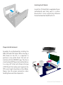
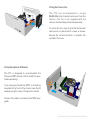
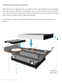
Page
2.................
3.................
4.................
5 - 6 ...........
7.................
8.................
9-11 ...........
12...............
13...............
14-15 .........
Index, Foreword
Product Overview
Preparation for Assembly
Installing the Motherboard
Installing Case Fan & Optional IRRC
Wiring Diagram
Fitting the Optical & Hard Drives
Installing a PCI Card
Replacing the Top Panel
Notes
Foreword
Thank you for your purchase of this Streacom product. Every care has been taken to
ensure that it meets with the highest standards and quality that we have set for
ourselves.
Should you have any questions that are not covered in this user guide, support can be
given via email through our website at www.streacom.com
We sincerely hope that you enjoy using our product!
P2 - INDEX
Specification
Chassis Material
Available Colours
Motherboard Compatibility
Hard Drive Support
Optical Drive Support
Component Cooling
Front Ports
External Dimensions
Expansion Slot
Power Supply Support
IR Support
Net Weight
2
3
4
1
Aluminum
Silver / Black - sandblasted finish
Mini ITX
1 x 2.5" + 1 x 2.5" or 3.5"
Slot loading drive, universal eject button
1 x 80x80x25mm Fan (Not Included)
2 x USB ports 2.0 & 3.0 compatible (USB 3.0 not included)
240 × 250 × 100mm (W×D×H)
1 x Low-profile expansion card
NanoPSU & external DC adapter (not included)
MCE compatible IR receiver & remote (not included)
2.5KG
5
6
11
8
7
9
10
12
13
14
Key Features
1...... Power Button
2...... Power LED
3...... ODD Loading Slot
4...... ODD Eject Button
5...... Top Panel
6...... USB Ports 2.0 & 3.0*
7...... IR Receiver Window
8...... DC Power Jack Hole
9...... 80mm Fan Bracket
10.... IO Shield Opening
11.... HDD/ODD Cage
12.... PCI Slot (Half-Height)
13.... USB PCB
14.... Power Button PCB
*Requires USB 3.0 cable which is sold separately
OVERVIEW - P3
Removing the Top Panel
The top panel is held in place with 4 screws, all
of which are accessible from the under side of
the chassis. Remove the screws and slide the
top panel upwards, away from the chassis.
Removing the HDD/ODD Cage
The HDD/ODD cage is held in place by 4 screws
which are all accessible from the top as
shown. Once all 4 screws are removed, lift the
cage out of the chassis.
P4 - PREPARING FOR ASSEMBLY
Installing the I/O Shield
Locate the I/O shield that is supplied with your
motherboard and firmly push it in place.
Ensure that it clicks in place fully otherwise
the motherboard will be difficult to fit.
Prepare the Motherboard
Assemble the motherboard by installing the
RAM, CPU and CPU Cooler. When choosing a
CPU Cooler for the F7C, it is important to
purchase a low profile Cooler that will not
interfere with the HDD/ODD cage. The choice
of motherboard (CPU position) and hard drives
(i.e. using a 3.5" drive), will influence the type
of CPU Cooler that can be used. In general, the
CPU cooler height should be less than 30mm.
Always take the proper precautions when
handling these sensitive components.
INSTALLING THE MOTHERBOARD - P5
Installing the Motherboard
Carefully lower the motherboard into the
chassis, with the I/O port side leading so
that the ports fit into the I/O shield.
When the motherboard is correctly in
position, fix it to the chassis stand-offs using
the screws provided. Ensure that all the
holes correctly align before fully tightening
the screws.
Connect the PSU & Other Cables
With the motherboard in place, you can now
connect the PSU and any other internal
connectors such as the power button switch.
You should also connect the SATA cables in
perpetration for installing the HDD/ODD cage
assembly.
Connect the front USB ports to the
motherboard with the cable supplied. See
diagram on next page for details.
P6 - INSTALLING THE MOTHERBOARD
Fitting the Chassis Fan
T h e F 7 C c a n a c c o m m o d a t e a s i n g le
80x80x20mm fan to extract warm air from the
chassis. The fan is not supplied with the
chassis and must be purchased separately.
To install the fan, align it with the fan bracket
and secure it in place with 2 screws as shown.
Ensure the airflow direction is towards the
outside of the case.
Fitting the Optional IR Module
The F7C is designed to accommodate the
Streacom IRRC remote control and IR receiver
(sold separately).
If you have purchased the IRRC, it should be
mounted to the front of the chassis near the IR
window using 2 screws in the position shown.
Connect the cables as shown in the IRRC user
guide.
INSTALLING THE CHASSIS FAN & IRRC (OPTIONAL) - P7
USB 2.0 Connector
Motherboard
USB
USB 3.0 Connector
USB 2.0 Cable x 2
GND
D+
D+5V
GND
D+
D+5V
USB
NC/SHIELD
GND
D+
D+5V
WARNING: Never connect USB 2
& USB 3 cables at the same time.
USB 3.0 Connector
Front USB Ports PCB
HDD+
HDDRESET1
RESET1
NC
USB 3.0 Cable (Sold Separately)
LED+
LEDPWS2
PWS2
LED+
LEDPWS1
PWS1
Chassis Power Switch PCB
Cable colours shown are for illustrative purposes only, actual colours will vary.
P8 - WIRING DIAGRAM
Fitting the Lower Hard Drives
With the cage out of the chassis, begin by fitting the lower hard drive. This procedure can be skipped
if you only plan to install a single 2.5" hard drive.
The lower mounting can accommodate either 1 x 3.5" or 1 x 2.5" hard drive. Depending on which drive
you are using, use the appropriate screws and mounting holes as shown. Please also ensure that the
CPU cooler fitted to the motherboard is low profile to allow for the extra height of a 3.5" drive.
1
1
2
2
1
2
1
2
1
2
FITTING THE OPTICAL & HARD DRIVES - P9
Fitting the Primary Hard Drive & Optical Drive
Before fitting the slot loading drive, affix a self adhesive rubber pad (included in the accessory bag) to
the drives eject button. Mount the slot loading drive using 4 screws, 2 either side. Do not fully tighten
the screws as the position of the drive will need to be adjusted to ensure correct operation of the eject
button. With left side eject buttons, 2 pads may be required.
The primary 2.5" hard drive is mounted behind the optical drive using 4 screws as shown in the
diagram.
Self Adhesive
Rubber Pad
P10 - FITTING THE OPTICAL & HARD DRIVES
Replacing the HDD/ODD Cage
With all the drives now fitted to the cage,
carefully lower it into the chassis. Note that the
front mounting points are under the screw
holes and the back are above.
Replace the 4 screws to secure the cage in
place.
Adjust the position of the optical drive so that
the drive eject button makes light contact with
the chassis eject button bar.
Test that the button operates correctly by
listening for the eject button clicking sound
when pressing the chassis eject button.
Once the correct position has been found,
tighten the 4 screws to secure the optical drive
in place.
FITTING THE OPTICAL & HARD DRIVES - P11
Installing PCI Card (Optional)
To install an expansion card, first remove the
pre-installed PCI blanking plate by removing
the single lower screw. The PCI mount can
also be removed to make it easier to install the
expansion card. This is done by removing the 2
screws either side on the mount.
Carefully place the card into the
motherboard slot ensuring the rear side
(where the ports are located) firstly passes
through the expansion slot opening of the
chassis. Once the card is fully seated into the
motherboard, replace the PCI mount and
finally secure the card with the single screw
from underneath the mount.
P12 - INSTALLING THE PCI CARD
Replace the Top Panel
With all the components installed, the chassis
can now be closed. Prior to doing this, ensure
that all cables are connected and all
components are securely fitted. Replace the
top panel and secure it in place using 4 screws
from under the chassis.
Connect Power & Other Cables
With the chassis now fully assembled, all that
remains is to connect the power and other
cables.
REPLACING THE TOP PANEL - P13
P14 - NOTES
NOTES - P15
Melbournestraat 56,
3047 BJ Rotterdam,
The Netherlands
www.streacom.com
V1.12.07