1
Controller operating unit
B 70.4045
Operating Instructions
3.98 00348855
Contents
1
Introduction
1.1
Preface .................................................................................................................. 5
1.2
Delivery package ................................................................................................. 5
1.3
1.4
Typographical conventions ................................................................................. 6
Type designation .................................................................................................. 7
2
Electrical connection
2.1
Notes on installation ............................................................................................ 8
2.2
Isolation ................................................................................................................ 9
2.3
Suitable cables ................................................................................................... 10
2.4
2.5
Connection diagram .......................................................................................... 11
Network connection .......................................................................................... 12
2.6
LON termination resistance .............................................................................. 14
3
Mounting in position
3.1
Location and climatic conditions ..................................................................... 15
3.2
3.3
Dimensions ......................................................................................................... 15
Fitting the operating unit in position ................................................................ 16
3.4
Removing the operating unit ............................................................................ 17
4
Displays and controls
18
5
Overview of functions
20
5.1
5.2
5.3
Controller operating unit ................................................................................... 20
Operating levels of the controller operating unit ............................................ 21
Controller module .............................................................................................. 22
6
Process level
6.1
6.2
Sequence of the process windows .................................................................. 23
Contents of the process windows ................................................................... 24
6.3
Editing the process windows ........................................................................... 26
7
Parameter level
29
7.1
7.1.1
7.1.2
7.1.3
7.1.4
7.1.5
7.1.6
Controller module ..............................................................................................
Module .................................................................................................................
Analogue input .....................................................................................................
Setpoints .............................................................................................................
Ramp ...................................................................................................................
Controller .............................................................................................................
Disturbance correction ........................................................................................
30
30
30
35
37
42
49
3.98/ JUMO mTRON controller operating unit
5
8
15
23
Contents
7.1.7
7.1.8
7.1.9
7.1.10
7.1.11
7.1.12
7.1.13
7.1.14
7.1.15
Self-optimisation .................................................................................................
Controller parameters ..........................................................................................
Pulse module .......................................................................................................
Mathematics ........................................................................................................
Limit comparator .................................................................................................
Control output conversion ...................................................................................
Analogue output ..................................................................................................
Logic output ........................................................................................................
Combination alarm ..............................................................................................
51
53
55
58
59
62
63
64
64
7.2
7.2.1
7.2.2
7.2.3
7.2.4
7.2.5
7.2.6
7.2.7
Controller operating unit ...................................................................................
Module .................................................................................................................
Process windows .................................................................................................
Alarm windows ....................................................................................................
Display .................................................................................................................
Logic input ...........................................................................................................
Logic output ........................................................................................................
Inhibits .................................................................................................................
65
65
66
66
66
67
67
69
8
Installation
70
8.1
Installation level ................................................................................................. 70
8.2
8.3
Operating several installations in one bus system ......................................... 71
Operating an installation with several operating units .................................. 72
9
Current alarms
9.1
9.1.1
9.1.2
Alarm windows .................................................................................................. 73
Range monitoring ................................................................................................ 73
Controller failure .................................................................................................. 74
10
Key combinations
75
11
Current module data
76
12
Specific module conditions
77
12.1
Action after a power failure .............................................................................. 77
12.2
Action on errors of communication ................................................................. 77
12.3
Action on faulty installation .............................................................................. 77
12.4
Display of symbols ............................................................................................ 77
73
3.98/ JUMO mTRON controller operating unit
1 Introduction
1.1 Preface
Please read these Operating Instructions carefully before starting up the
instrument.
Keep the manual in a place which is at all times accessible to all users.
Please assist us to improve this manual wherever necessary.
Your suggestions will be most welcome.
Phone:
Germany
abroad
Fax:
Germany
abroad
(0661) 60 03-727
(int. +49) 661 6003-0
(0661) 6003-508
(int. +49) 661 6003-607
With the controller operating unit it is possible to
1. set the parameters for all modules in the system,
2. display and alter process variables during operation,
3. output an alarm in the event of a system failure or error,
4. switch the user language over to English, German or French.
H
Trademarks
If the instrument does not respond as described in the Operating
Instructions, you are asked not to carry out any manipulations on
the unit which are not permitted. You could endanger your rights
under the instrument warranty. Please contact the nearest office or
the main factory.
LON and Neuron are registered trademarks of the Echelon Corporation.
1.2 Delivery package
Please check each delivery for completeness and damage.
If anything is missing or damaged, please contact the nearest office or the
main factory.
The equipment supplied consists of:
- the JUMO mTRON controller operating unit,
- Operating Instructions,
- 1 plug-in connector with screw terminals
- 2 mounting brackets.
3.98/ JUMO mTRON controller operating unit
5
1 Introduction
1.3 Typographical conventions
Warning signs
V
A
The signs for Danger and Warning are used in this Manual under the following
conditions:
Danger
This symbol is used when there may be danger to personnel if the instructions
are disregarded or not followed accurately!
Warning
This symbol is used if there may be danger to equipment or data if the instructions are disregarded or not followed accurately!
Note signs
H
v
abc1
Note
This symbol is used when your special attention is drawn to a remark.
Reference
This symbol refers to further information in other handbooks, chapters or
sections.
Footnote
Footnotes are notes which refer to certain points in the text. Footnotes consist
of two parts:
Marking in text and footnote text.
The markings in the text are arranged as continuous raised numbers.
The footnote text (in smaller typeface) is placed at the bottom of the page and
starts with a number and a full stop.
h
Action
This symbol indicates that an action is described. The individual steps are marked by this asterisk, e.g.:
h switch off the supply
h pull connectors off the module
6
3.98/ JUMO mTRON controller operating unit
1 Introduction
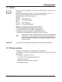
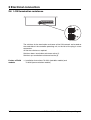
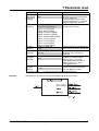
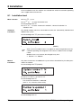
1.4 Type designation
The type code of the controller operating unit only specifies the supply voltage
(1), which must correspond to the voltage shown on the label.
The label is affixed to the housing.
(1)
704045 /0- . .
(1) Supply............................................................................ . .
Type
Code
93 — 263V AC 48 — 63Hz
01
20 — 53V DC/AC 0/48 — 63Hz
22
3.98/ JUMO mTRON controller operating unit
7
2 Electrical connection
2.1 Notes on installation
❏
The choice of cable, the installation and the electrical connection of
the controller operating unit must conform to the requirements of
VDE 0100 “Regulations on the installation of Power Circuits with nominal voltages below 1000 V”, or the appropriate local regulations.
❏
Work on the controller operating unit must only be carried out to the
extent described and, like the electrical connection, only by properly
qualified personnel.
❏
If contact with live parts is possible when working on the controller
operating unit, it has to be isolated on both poles from the supply.
❏
The external fuse of the supply should not be rated above 10A (slow).
❏
Electromagnetic compatibility conforms to the standards and
regulations listed under Technical Data.
v Data Sheet 70.4045 “Technical Data”
8
❏
The controller operating unit is not suitable for installation in
hazardous areas.
❏
Run input, output and supply lines separately, and not parallel to
each other.
❏
If no technical earth is available in the system, connect terminal TE on
the module to the protective earth (PE).
❏
Earth the LON interface at both ends on terminal TE.
❏
Do not loop earth connections, i.e. do not run them from one module
to another; run them singly, e.g. to earth terminals on the rail (short
leads!).
❏
Apart from faulty installation, incorrect settings on the module may
interfere with the proper operation of the subsequent process. Provision should therefore always be made for safety devices independent
of the module, such as overpressure valves or temperature limiters/
monitors. Setting up must be restricted to properly qualified personnel. Please refer to the appropriate safety regulations in this connection.
3.98/ JUMO mTRON controller operating unit
2 Electrical connection
❏
Setup interface and inputs are not isolated.
If any inputs are carrying a voltage, they have to be disconnected before the setup operation with a grounded PC, or carry out setup with
an unearthed PC or laptop.
❏
Pull off plug connectors with screw terminals only when the circuits
are de-energised.
2.2 Isolation
3.98/ JUMO mTRON controller operating unit
9
2 Electrical connection
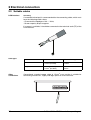
2.3 Suitable cables
LON interface
Screening
A screened twisted pair is recommended for the connecting cable, which must
have the following cable values:
- Characteristic impedance 100 — 120Ω,
- Screen capacity 60pF/m approx.
If a screen is available, it should be connected to the technical earth (TE) of the
LON interface.
Cable types
Other
connections
10
Structure
Cable cross-section
Max. cable length
Line
1.4 mm2 (16 AWG)
0.34mm2 (22 AWG)
2700m
1400m
Ring/star/mixed
1.3 mm2 (16 AWG)
0.34mm2 (22 AWG)
500m
400m
Conventional stranded copper cable of 1.5mm2 cross-section is suitable for
connecting transducers, supply and logic inputs to screw terminals.
3.98/ JUMO mTRON controller operating unit
2 Electrical connection
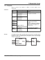
2.4 Connection diagram
Module underside
with plug-in
connector
Connector
Switches for
termination resistance
V
The electrical connection
must only be carried out by
properly qualified personnel!
A
The supply must correspond to the
voltage specified on the label.
Connection for
Terminals
Logic inputs
Input 1
Input 2
Notes
Floating contacts
1
3
2
3
Logic output
5V 40 mA
4 +
3 −
LON interface
7 = TE
screen
6 = Net_A
5 = Net_B
any
polarity
Diagram
9 = not used
Supply
as label
AC
UC=DC/AC
L1 line
N neutral
TE technical earth
L1
N
TE
3.98/ JUMO mTRON controller operating unit
any
} polarity
technical
earth
11
2 Electrical connection
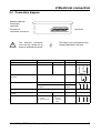
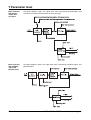
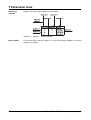
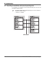
2.5 Network connection
LON
The JUMO mTRON automation system incorporates the fieldbus network
concept called LON (Local Operating Network).
A screened twisted pair is used as a transmission line.
The connection can be made as line, ring, star or mixed structure
(free topology):
Line structure
The mechanical ends are provided at both ends with a termination resistance
which is activated by a switch on the module.
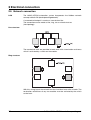
Ring structure
With this wiring layout the network remains functional even after a break. The
termination resistances of any two modules must be activated by the switch
on the front.
12
3.98/ JUMO mTRON controller operating unit
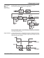
2 Electrical connection
Star structure
In this wiring layout the termination resistances of any two modules have to be
activated.
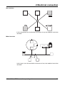
Mixed structure
In this layout, too, the termination resistances of any two modules have to be
activated.
3.98/ JUMO mTRON controller operating unit
13
2 Electrical connection
2.6 LON termination resistance
The switches for the termination resistance of the LON network are located on
the underside of the controller operating unit, to the left of the plug-in screw
connectors.
h Set the switches as required
Switches down: termination resistance active (1)
Switches up: termination resistance inactive (2)
Further mTRON
modules
14
v Installation Instructions 70.4010 (controller module) and
70.4040 (communication module)
3.98/ JUMO mTRON controller operating unit
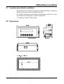
3 Mounting in position
3.1 Location and climatic conditions
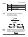
The operating unit is suitable for fitting into control panels/doors. Protection is
IP65 on the front and IP20 at the back (EN 60 529).
The ambient temperature at the location can be between 0 and 50°C at a relative humidity not exceeding 80% without condensation.
v Data Sheet 70.4035 “Technical data“
3.2 Dimensions
3.98/ JUMO mTRON controller operating unit
15
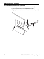
3 Mounting in position
3.3 Fitting the operating unit in position
h Insert the operating unit into the panel cut-out from the front (1)
h Insert the mounting brackets into the recesses at the sides (2)
h Tighten up the mounting brackets evenly against the back of the panel (3)
16
3.98/ JUMO mTRON controller operating unit
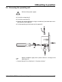
3 Mounting in position
3.4 Removing the operating unit
V
Switch off the power supply!
h Pull off the setup plug (1)
h Pull off the connector (2)
h Release the mounting brackets using a screwdriver (3) and take them out of
the recesses at the sides (4)
h Pull the operating unit forward out of the panel (5)
H
Special conditions apply after a power failure or a change of the
operating unit.
v System Manual Part 8, Section 6.1 “Overview of levels”
3.98/ JUMO mTRON controller operating unit
17
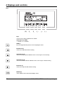
4 Displays and controls
Keys
(1)
(2)
(3)
(4)
(5)
(6)
Keys
six keys on the front to operate the module
Setting the key inhibit
v Section 7.2.7 “Inhibits”
P
l
PGM (1)
key to change between process level and program levels
o
Selection key (3)
selects forwards between different items in the ring list / incrementing
u
Selection key (4)
selects backwards between different items in the ring list / decrementing
r
Forwards (5)
moves one step forwards without storing
E
18
Backwards (2)
moves one step back without storing
ENTER (6)
stores edited values and acknowledges alarms
3.98/ JUMO mTRON controller operating unit
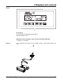
4 Displays and controls
Display
(7)
LC display (7)
2x 20 characters for displaying texts and data
Character height: 5.5mm
Adjusting contrast, language, switch-off time and display darkening
v Section 7.2.4 “Display”
Interface
Is only required in connection with the JUMO mTRON - iTOOL project design software.
(9)
3.98/ JUMO mTRON controller operating unit
19
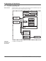
5 Overview of functions
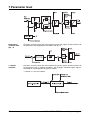
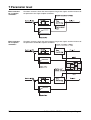
5.1
Controller operating unit
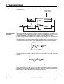
Block structure
The block diagram shows the module function (framed), with the hardware inputs indicated on the left, and the hardware output on the right..
Setting the
parameters for
the functions
v Chapter 7 “Parameter level”
20
3.98/ JUMO mTRON controller operating unit
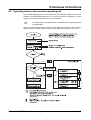
5 Overview of functions
5.2
Operating levels of the controller operating unit
The controller operating unit can be on different levels. After the supply has been switched on, the controller operating unit first assesses its network surrounding, i.e. which
modules are connected and their names (reset window).
A module with the setup connector inserted will not be found during the
reset procedure.
Then the controller operating unit switches automatically to the process level, where it
displays process windows. Errors and alarms are indicated as soon as they occur.
3.98/ JUMO mTRON controller operating unit
21
5 Overview of functions
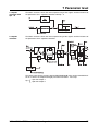
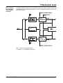
5.3
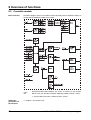
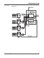
Controller module
Block structure
The block diagram shows the module function (framed), with the hardware inputs on
the left and the hardware outputs on the right.
H
Setting the
parameters for
the functions
22
Network-variable inputs/outputs are shown as arrows on the function
blocks. They can only be used when operating JUMO mTRON - iTOOL:
v System Manual 70.4000 “JUMO mTRON - iTOOL”
v Chapter 7 “Parameter level”
3.98/ JUMO mTRON controller operating unit
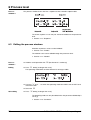
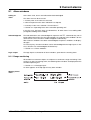
6 Process level
“Process level” means the cyclic sequence of process windows and, if appropriate,
also their operation.
6.1
Sequence of the process windows
The controller operating unit displays 4 different process windows for each controller
module. All connected controller modules are run through on the same level either
cyclically or by manual operation (adjustable via scroll time).
Set scroll time
v Section 7.2.2 “Process windows”
The diamond () indicates whether the scroll operation is activated:
() blinks cyclically: Controller modules 1 —n are run through cyclically in
ascending order
() is stationary:
Controller modules 1 —n can be switched over manually by keys
Manual
changeover
h Use the Ekey to hold a process window
(the diamond stops blinking)
h With the o and u keys, select the process windows of a controller
h Using the l and r keys, select the controllers on one process window level
Scroll operation
h Continue the cyclic sequence of the process windows with E
(diamond blinks)
3.98/ JUMO mTRON controller operating unit
23
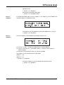
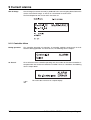
6 Process level
6.2
Contents of the process windows
4 types of process windows are available.
Process
window 1
The process window shows the controller values of the controller module:
Module name:
Name of the controller module
Unit:
Physical unit of the setpoint and process value
Operating mode: MAN., AUTO, TUNE
Setpoint:
Setpoint of the controller function
Process value: Process value of the controller function
Process
window 2
This process window shows the input variables of the controller module:
Module name: Name of the controller module
b1, b2:
Logic inputs 1 and 2
I1, I2:
Analogue inputs 1 and 2
24
3.98/ JUMO mTRON controller operating unit
6 Process level
Process
window 3
This process window shows the output variables of the controller module.
Modulating
controller
Controller output Y: Indicates which switching output is currently active
Module name:
Name of the controller module
Controller output Y: K1, Zero, K2
Process value:
Process value of the controller function
Switching state relay K1: 0.1
Switching state relay K2: 0.1
In the case of double-setpoint and modulating controllers, the selector of
the logic output 2 must be set to “Pulse 2” [1] instead of “Limit
comparator” [2].
v Section 7.1.14 “Logic output”
All other
controllers
On double-setpoint controller set Ymin from 0 to -100
v Section 7.1.8 “Controller parameters”
If the controller is in manual operation, output Y can be edited.
3.98/ JUMO mTRON controller operating unit
25
6 Process level
Process
window 4
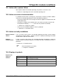
This process window shows the first 3 setpoints of the controller setpoint table.
The fourth setpoint w4 can only be viewed and edited at the parameter
level.
v Section 7.1.3 “Setpoints”
6.3
Editing the process windows
Alteration to process values can be inhibited.
v Section 7.2.7 “Inhibits”
The module name can be edited through the parameter level.
v Section 7.1.1 “Module”
Process
window 1
Editing
h Hold the scroll operation with
E (the diamond
is stationary)
h Press P briefly (no longer than 2sec)
The operating mode blinks and the diamond is no longer visible.
.
h Use keys o and u to switch the operating mode from MAN. over to AUTO and
switch off TUNE.
h Save with
Quit editing
h Press
E
P briefly (no longer than 2sec)
The operating mode can only be edited when the parameter SelManOp is
set to [3].
v Section 7.1.5 “Controller”
26
3.98/ JUMO mTRON controller operating unit
6 Process level
Altering the unit:
v Section 7.1.3 “Setpoints”
Activating the operating mode TUNE:
v Section 7.1.1 “Self-optimisation”
Process
window 3
As already described under “Process window 1”, the output Y can be edited if the
controller module is in MANUAL mode.
The output can only be edited if the parameter SelManOut is set to [2].
v Section 7.1.5 “Controller”
Process
window 4
The three setpoints can be edited as described in Section 6.3.1.
.
h Use keys o and u to edit the variable which is currently blinking
h Use key r to select w1—w3 forwards and key l for the reverse sequence
(without saving)
h Save with E and continue to the next value to be edited.
The setpoints can be selected via the 2 logic inputs.
Address 1 = [2]
Address 2 = [3]
v Section 7.1.3 “Setpoints”
The fourth setpoint w4 can only edited at the parameter level.
v Section 7.1.3 “Setpoints”
3.98/ JUMO mTRON controller operating unit
27
6 Process level
This page is left blank deliberately, for clarity of presentation !
28
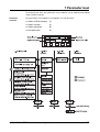
3.98/ JUMO mTRON controller operating unit
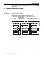
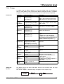
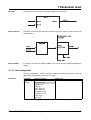
7 Parameter level
At the parameter level, the parameters of all modules can be indicated and edited
using a uniform method.
Parameter
selection
The parameters of all modules are arranged in a 4-step hierarchy:
h Select mTRON module
(1)
h Select function
(2)
h Select parameter
(3)
h Edit parameter
(4)
3.98/ JUMO mTRON controller operating unit
29
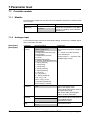
7 Parameter level
7.1 Controller module
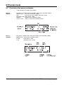
7.1.1
Module
A characteristic module name for the task of the module in the process facilitates work
on the system.
Parameter
Selection/settings
Module name
[Modname]
(Text)
Controller
k = factory setting
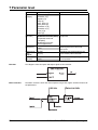
7.1.2
Explanation
Name of the module (16 characters)
Only the first 8 characters are visible in
the process windows of the controller
operating unit.
[ ] = short name in the controller operating unit
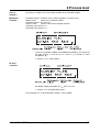
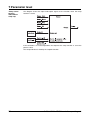
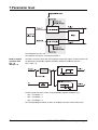
Analogue input
2 measurement inputs measure thermocouple voltage, resistance or standard signals
which are listed in the table.
[AnalogInp1],
[AnalogInp2]
Parameter
Selection/settings
Explanation
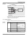
Sensor
[Sensor]
No sensor connected
[NoSens] (channel 1)
Thermocouple
CJ temperature internal [CJInt]
Thermocouple
CJ temperature constant
[CJ const]
Potentiometer [Potent]
0—400Ohm [0/400Oh] (channel 2)
0—50mV [0/50mV]
0—10V [0/10V]
2—10V [2/10V]
0—20mA [0/20mA]
4—20mA [4/20mA]
0—1V [0/1V]
0.2—1V [0.2/1V]
10—50mV [10/50mV]
-1 to +1V [-/+1V]
-10 to +10V [-/+10V]
0—50mA AC [50mA AC]
-50 to +50mV [-/+50mV]
-1999 to +9999 unit
0 unit
Defines the transducer to be
connected to the specific analogue
input
Scaling start
[ScalStart]
Scaling end
[ScalEnd]
Unit
[Unit]
-1999 to +9999 unit
100 unit
“0 — 400Ω” must be set for the
Pt100 transducer!
Heater current 0 — 50mA AC with
analogue input 2 only!
With standard signals, potentiometer and heater current:
Defines the display value
(measurement) of the start value of
the signal input range.
With Pt100 and thermocouples:
makes an offset correction.
The value defines the display value
(measurement) for the end value of
the standard signal or
potentiometer range.
Defines the physical unit of the
measurement value
(various)
°C [°C]
k =factory setting [ ] = short name in the controller operating unit
30
3.98/ JUMO mTRON controller operating unit
7 Parameter level
Parameter
Selection/settings
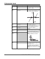
Explanation
Constant
cold junction
temperature
[CJTemp]
-5 to +100°C
50°C
Linearisation
[Linearisn]
Linear [Linear] (channel 2)
Pt100 [Pt100] (channel 1)
Type L: Fe-Con [TypeL]
Type K: NiCr-Ni [TypeK]
Type S: Pt10Rh-Pt [TypeS]
Type R: Pt13Rh-Pt [TypeR]
Type B: Pt30Rh-Pt6Rh [TypeB]
Type U: Cu-Con [TypeU]
Type T: Cu-Con [TypeT]
Type J: Fe-Con [TypeJ]
Type N: Ni-CrSi [TypeN]
-1999 to +9999 unit
0 unit
-1999 to+9999 unit
100 unit
Indicates the cold junction
temperature of the thermocouple.
It is only valid when
“Thermocouple constant cold
junction temperature” is selected
under the parameter “Sensor”.
Determines the linearisation
function for the sensor
Min. limit
[MinLimit]
Max. limit
[MaxLimit]
Warning
differential
[WarnDiff]
-1999 to +9999 unit
0 unit
Filter time
constant
[FiltTime]
0.0 — 40.0sec
1.0sec
k =factory setting
Function
If the measurement falls below the
preset value, an alarm is produced.
If the measurement goes above
the preset value, an alarm is
produced.
The value of the process value
produces a warning alarm if:
process value > max. limit warning differential and also if:
process value < min. limit +
warning differential.
The time constant which is used
to filter the measurement value
with two digital PT1 filters.
[ ] = short name in the controller operating unit
The block structure shows the input and output signals of the function.
3.98/ JUMO mTRON controller operating unit
31
7 Parameter level
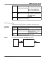
Block structure
with thermocouple and
resistance
The block diagram shows the signal flow when connecting thermocouples and
resistances/resistance thermometers of the Pt100 type.
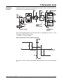
Block structure
with standard
signal and
potentiometer
The block diagram shows the signal flow when connecting standard signals and
potentiometers.
32
3.98/ JUMO mTRON controller operating unit
7 Parameter level
Block structure
with
AC current
(heater current)
The block diagram shows the signal flow when connecting an AC current.
An AC current can only be measured via the analogue input 2.
The AC current (heater current) is measured with the heating contact closed (operation
via the pulse module 1 (pulse 1 = 1)). The measurement is held until the next measurement (sample-and-hold element).
Range monitoring
A range monitoring function is integrated into each of the analogue input functions.
This function can be freely set via parameter to monitor the measurement. The alarm
signals (AIx_alarm, AIx_warning ) are available as output network-variables and can be
used to link up with other functions.
3.98/ JUMO mTRON controller operating unit
33
7 Parameter level
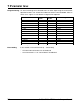
Range monitoring
On over/underrange of the selected current or voltage input range, the measurement
itself is characterised as an invalid value by the “Out-of-Range” message, so that the
operated functions can evaluate the invalid measurement. The table below shows on
which sensor signals a sensor break is recognised and reported.
Transducer
Resistance thermometer
Thermocouples
0—50mV
10—50mV
-50 to +50mV
0—10V
2—10V
-10 to +10V
0—1V
0.2—1V
-1 to +1V
0—20mA
4—20mA
AC 0—50mA
Potentiometer
X = recognised
Error handling
34
Sensor
Shortbreak
circuit
X
X
X
–
X
–
X
X
X
–
–
–
X
X
–
–
–
–
X
X
–
–
–
–
X
X
–
–
X (slider)
–
— = not recognised
Max. overrange
0%
0%
+/-20%
+/-20%
+/-10%
+/-20%
+/-20%
+/-10%
+/-20%
+/-20%
+/-10%
+/-20%
+/-20%
+/-10%
0%
In the event of a measurement error (e. g. sensor break),
-
the alarm and warning alarm are activated and
-
the measurement is set to “Out-of-Range” (invalid value).
3.98/ JUMO mTRON controller operating unit
7 Parameter level
7.1.3
Setpoints
There is a choice of four setpoints. In addition, an external setpoint can be
implemented.
Parameters
Parameter
Selection/settings
Unit
[Unit]
(various)
°C
Address 2
Setpt_Addr1 [0]
[SelAddress2] Setpt_Addr2 [1]
Logic_In 1 [2]
Logic_In 2 [3]
Setpt_Addr1 [0]
Address 1
[SelAddress1] Setpt_Addr2 [1]
Logic_In 1 [2]
Logic_In 2 [3]
Setpoint 4
[Setpt 4]
Setpoint 3
[Setpt 3]
Setpoint 2
[Setpt 2]
Setpoint 1
-1999 to +9999 unit
[Setpt 1]
0 unit
Explanation
Determines the physical units of the
setpoints
Determines via which signal sources
the setpoints are selected
Four setpoints can be programmed,
which can be selected either by the logic inputs or by two network
variables.
An external setpoint can be added to
setpoint 1. This provides an external
setpoint which uses setpoint 1 as a
correction value.
External
setpoint
[SelExtSetp]
No function [0]
The selected external setpoint is
added to the given setpoint 1.
Setpt_Ext [1]
AnIn1_Meas [2]
AnIn2_Meas [3]
k = factory setting [ ] = short name in the controller operating unit
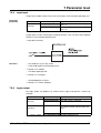
Function
The diagram shows the input and output signals of the function. The output signal of
the setpoint function is firmly linked to the ramp function. If the status of the ramp
function is on “OFF”, the output signal of the setpoint function is passed straight
through the ramp function.
3.98/ JUMO mTRON controller operating unit
35
7 Parameter level
Addressing
setpoints
Setpoints are selected according to the table below:
setpoint 1* = setpoint 1 + external setpoint
Error handling
36
If the function input “External setpoint” is in the Out-of-Range condition, it is passed
through to the output.
3.98/ JUMO mTRON controller operating unit
7 Parameter level
7.1.4
Ramp
A setpoint ramp with different gradients for rising and falling ramps can be implemented. The ramp profile can be influenced by different operating functions. In addition,
the process value can be monitored with regard to the setpoint (stop comparator).
Parameters
Parameter
Selection/settings
Explanation
Start
[SelStart]
Controller process value [0]
Ramp_Start [1]
Start profile [2]
Defines the start condition for the ramp
Unit gradient
[UnitGrad]
1/min [1/min]
1/h [1/h]
1/day [1/day]
-1999—0unit
-10 unit
Defines the physical unit of the
gradient
With an active ramp reset, the ramp
output equals the value of the ramp
start.
Window symmetrical [WinSym] The selected stop function defines the
Condition
process value range in which a ramp
for stop
Comparator high [CompHi]
stop is active.
[CondStop]
Comparator low [CompLow]
Ramp_Off [0]
The ramp output corresponds to the
Off
ramp end, i.e. the preset setpoint.
[SelOff]
Logic input 1 [1]
Logic input 2 [2]
Ramp_Reset [0]
The actual setpoint is set to the ramp
Reset
start by the ramp reset.
[SelReset]
Logic input 1 [1]
Logic input 2 [2]
Ramp_Stop [0]
External signal which stops the ramp
Stop
output.
[SelStop]
Logic input 1 [1]
In addition, the stop comparator
Logic input 2 [2]
compares the control variable (process
value) with the actual ramp output. The
ramp is stopped if the control
variable is outside the preset range.
Ramp function Off [Off]
Altogether two ramp types can be
[RampFunct] Ramp active [RampAct]
activated.
Ramp active
with ramp stop [RampStp]
Difference for 0—9999 unit
Defines the limit value for ramp with
stop
ramp stop
0.5 unit
[DiffStop]`
Gradient
negative
[GradntNeg]
Gradient
positive
[GradntPos]
0—99990unit
10 unit
Profile start
[Start]
These two variables determine the
speed of the ramp change.
The parameter “Gradient positive”
is active when:
ramp output < ramp end.
The parameter “Gradient negative” is
active when:
ramp output > ramp end.
Defines a value for the ramp start
-1999 to +9999 unit
0 unit
k = factory setting [ ] = short name in the controller operating unit
“Ramp off”
function
The diagram shows the input and output signals of the function when the ramp
function is on “OFF”.
The “actual” setpoint is looped through and appears at the output (ramp).
3.98/ JUMO mTRON controller operating unit
37
7 Parameter level
“Ramp active”
function
with/without
ramp stop
The diagram shows the input and output signals of the function when the ramp
function is active.
If the controller is in manual operation, the output of the ramp function is set to the
process value.
The ramp end value is fixed by the setpoint function.
38
3.98/ JUMO mTRON controller operating unit
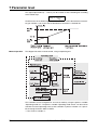
7 Parameter level
Block structure
The block structure shows the internal processing of the signals and the influence of
the parameters.
3.98/ JUMO mTRON controller operating unit
39
7 Parameter level
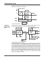
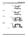
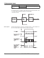
Ramp profile
On a setpoint change (ramp end), the parameters Gradient positive/negative become
effective in the following way:
The diagram below shows the ramp profile with different operating functions and module conditions.
40
3.98/ JUMO mTRON controller operating unit
7 Parameter level
Ramp active with
stop comparator
The progress of the process value along the ramp profile can be monitored by the selectable comparators which are available. Using the parameter Difference for ramp
stop, the distance to the ramp output signal can be set.
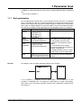
Error handling
Source
Response of “Output ramp” on Out-of-Range
Start
-
Output produces Profile start in the event of a (ramp) reset
Ramp end value
-
Output is set to Out-of-Range
When the error has been corrected, the output is set to the
controller process value.
Controller
process value
-
Ramp output is Out-of-Range
When the error has been corrected,
the ramp function outputs the following value if
-
a (ramp) stop has been activated
Profile start
-
a (ramp) reset has been activated
Profile start
-
a (ramp) Off has been activated
Ramp end
-
manual operation has been activated
Ramp setpoint = process value
3.98/ JUMO mTRON controller operating unit
41
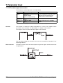
7 Parameter level
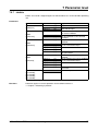
7.1.5
Controller
Different controller types can be configured here.
Parameters
Parameter
Selection/settings
Controller type 1-setp. controller/
[ContrType]
prop. controller [1SptCon]
2-setpoint controller [2SptCon]
Modulating controller
[ModCon]
Prop. controller with
act. driver [ActCont]
Out of Range Manual output prog. [0]
output
[SelOutROut]
Manual output Contr_ManOut [0]
[SelManOut]
Controller output [1]
Manual output prog. [2]
Contr_Manual [0]
Manual
operation
Logic input 1 [1]
[SelManOp]
Logic input 2 [2]
Operating unit [3]
No function [0]
Controller
output
AnIn2_Meas [1]
retransmission
Contr_OutRetr [2]
[SelOutRetr]
Controller
parameter set
[NrActPara]
Parameter set
selection
[SelParSeln]
[0]
[1]
Contr_Para [0]
Logic input 1 [1]
Logic input 2 [2]
Operating unit [3]
Manual output -100 to +100%
prog.
0%
[ManOutProg]
[Man.]
Operating
mode actual
[Auto]
[OperAct]
Operating
[Man.]
mode set
[Auto]
[OperSet]
Explanation
The functionality of the controller is
defined here. The controller types are
described below.
Signal source for output which is produced in the event of process value or
setpoint errors
Signal source for the control output in
manual operation
Signal source for changeover to
manual operation
v “Manual operation”
Signal source for output retransmission on modulating controllers and proportional controllers with integral actuator driver
Active parameter set for controller
Signal source for parameter set
switching
Fixed controller output which is to be
output in manual operation
The current operating mode appears
here
The setting for manual operation
[SelManOp] must be on [3]. Then it is
possible to change over from “Manual”
to “Auto” via the controller operating
unit.
Signal source for the controller
process value.
Process value AnIn1_Meas [0]
[SelProcVal]
AnIn2_Meas [1]
Maths [2]
Contr_ExtPV [3]
Ramp [0]
Signal source for the controller
Setpoint
setpoint.
[SelSetpt]
Maths [1]
Setpoint [2]
k = factory setting [ ] = short name in the controller operating unit
42
3.98/ JUMO mTRON controller operating unit
7 Parameter level
Parameter
Selection/settings
Explanation
Characteristic Direct (cooling) [Direct]
Defines the controller characteristic
[Charistic]
Reversed (heating) [Reversd]
With the setting “Characteristic
reversed” the control deviation (xw) is
formed from w - x. The output Y of the
controller is > 0, if the process value is
smaller than the setpoint. If the characteristic is switched to “Characteristic direct”, then the controller output
Y is > 0 if the process value is larger
than the setpoint.
Transfer characteristic of the controller
for controlling the process
Controller
structure
[Structure]
P [P]
I [I]
PD [PD]
PI [PI]
PID [PID]
k = factory setting [ ] = short name in the controller operating unit
Function
The diagram shows the input and output signals of the function.
v Section 7.1.8 “Controller parameters”
Proportional
controller
The block structure shows the internal processing of the signals and the influence of
the parameters with proportional controllers.
v “Additive disturbance”
“Multiplying disturbance”
3.98/ JUMO mTRON controller operating unit
43
7 Parameter level
Proportional
controller with
Xp1 = 0
The block structure shows the internal processing of the signals and the influence of
the parameters with proportional controllers with Xp = 0.
1-setpoint
controller
The block structure shows the internal processing of the signals and the influence of
the parameters with 1-setpoint controllers. The analogue controller output signal is
converted to switching pulses by a pulse module.
v Section 7.1.9 “Pulse module”
44
3.98/ JUMO mTRON controller operating unit
7 Parameter level
1-setpoint
controller with
Xp1 = 0
The block structure shows the internal processing of the signals and the influence of
the parameters for 1-setpoint controllers with Xp = 0.
2-setpoint
controller
The block structure shows the internal processing of the signals and the influence of
the parameters for 2-setpoint controllers.
The preset value for the contact spacing XSh (dead band) refers to the control deviation xw. It affects the output limiting by an amount of XSh/2 · 100%/Xp.
Xp1 with output 1
Xp =
Xp2 with output 2
{
3.98/ JUMO mTRON controller operating unit
45
7 Parameter level
The inhibit prevents the status pulse 1 = pulse 2 = 1.
The replacement value is set on pulse module 1.
Double-setpoint
controller with
Xp1 = 0
and Xp2 = 0
The block structure shows the internal processing of the signals and the influence of
the parameters for double-setpoint controllers without a feedback structure
(Xp1 = Xp2 = 0).
Further mixed structures can be set up for double-setpoint controllers, e.g.
-
Xp1 > 0 and Xp2 > 0
-
Xp1 = 0 and Xp2 > 0
-
Xp1 > 0 and Xp2 = 0
The corresponding functional sections of the block structures will then be active.
46
3.98/ JUMO mTRON controller operating unit
7 Parameter level
Modulating
controller
The block structure shows the internal processing of the signals and the influence of
the parameters for modulating controllers.
When the integrating effect of the actuator motor is considered, the result is a PI or
PID response for the control system.
v Section 7.1.9 “Pulse module”
Static characteristic of the actuator operation
The value set for the contact spacing XSh (dead band) refers to the control deviation
xw.
3.98/ JUMO mTRON controller operating unit
47
7 Parameter level
Apart from the effect of the D-element, the control deviation (xw) must lie outside the
dead band, so that pulses can be produced.
YR - output retransmission
Proportional
controller with
integral actuator
driver
∆YR
------------ = 100
--------TT
∆t
The block structure shows the internal processing of the signals and the influence of
the parameters for a proportional controller with integral actuator driver.
The advantages of the actuator driver:
An actuating controller has the advantage over a modulating controller of providing a
subordinate control loop. If a control deviation occurs, the actuator driver runs the motor to a new position. This is achieved by comparing the actuator position with the
controller output of the proportional controller. An actuating controller is more dynamic
than a modulating controller in correcting a control deviation. The subordinate control
loop, consisting of the actuator driver and the motor actuator, forms a PDT1 transfer
function. This control loop can be adjusted by the value entered for the actuator stroke
time TT. In this case, the setting and effect of the parameter XSh refers to the output
difference, not the control deviation. With an entered value of, for instance, 3% for
XSh, no further pulses will appear in a range of +/- 1.5% about the output variable
(output1) (see “Modulating controller”).
48
3.98/ JUMO mTRON controller operating unit
7 Parameter level
Error handling
7.1.6
Source
Response on Out-of-Range
Process value
-
Produces an Out-of-Range output
Setpoint
-
Produces an Out-of-Range output
Output
retransmission
-
Output corresponds to the replacement value
of the pulse module (only with actuating controllers!)
Manual output
-
Output of Manual output prog. (only in manual mode!)
Additive
disturbance
-
Disturbance correction inactive
Multiplying
disturbance
-
Disturbance correction inactive
Disturbance correction
Additive
disturbance
correction
The additive disturbance correction (DisAdd) has the effect of shifting the output relative to the controller output variable (Y) and the preset working point (YO).
The additive disturbance correction is made so that it compensates for the disturbing
influence (z) acting on the input of the process.
In order to achieve this compensation of the disturbance, the DisAdd signal must be
equal to the disturbance z, but of opposite sign.
The dimension of the DisAdd signal is scaled as % of the shift in the output.
Multiplying
disturbance
correction
The multiplying disturbance correction alters the gain factor in the transfer function of
the controller. This makes it possible to adjust the controller gain to match a varying
process amplification. To do this, it must be possible to measure the change of amplification in the process.
The gain factor (Kp) can be calculated from the preset proportional band (Xp) as
Kp = 100%
-------------Xp
3.98/ JUMO mTRON controller operating unit
49
7 Parameter level
The signal input DisMul (0 — 1000%) can be used to set the controller gain according
to the relationship
Kp = DisMul
------------------Xp
The dimension of the DisMul signal must be scaled in % of the desired normal controller gain. DisMul = 100 means that the disturbance correction is switched off.
Manual operation
The diagram illustrates manual control, using an operating unit.
The controller can be changed over to manual mode by using the process variable
“Operating mode set”. The process variable “Operating mode actual” can be used to
read out the actual operating status of the controller. In process window 1 it is possible to change over from MAN. to AUTO.
v See “Process window 1”
50
3.98/ JUMO mTRON controller operating unit
7 Parameter level
In addition, the parameter Manual output prog. can be provided through the operating
unit.
v See “Process window 3”
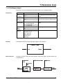
7.1.7
Self-optimisation
The self-optimisation function SO is a pure software function unit which is integrated
into the controller. The SO uses a special procedure to investigate the response of the
process to an output step. The process response (process value) of the control loop is
then used in a complex algorithm to calculate and then store the controller parameters
for a PID or PI controller. The SO procedure can be repeated as often as is required.
Parameter
Selection/ settings
Explanation
Start
[SelStart]
Tune_Start [0]
Logic input 1 [1]
Logic input 2 [2]
Operating unit [3]
Relay [Relay]
Analogue [Analog]
Semicoductor [Semicon]
Relay [Relay]
Analogue [Analog]
Semiconductor [Semicon]
Starts the self-optimisation
Output
mode 2
[OutpMode]
Output
mode 1
[OutpMode]
The controller parameter are calculated according to the output mode.
For relay outputs: the Cycle time
parameter is calculated for the pulse
modules.
For semiconductor relay outputs:
the Cycle time parameter is fixed at 8 x
controller sampling time.
For analogue outputs: there is no optimisation of the Cycle time parameter.
Starts the self-optimisation when “yes”
is entered, if [3] has been configured
for “Start”.
No start of self-optimisation
[no]
Start self-optimisation [yes]
k = factory setting [ ] = short name in the controller operating unit
________
[Start]
Function
The diagram shows the input and output signals of the function.
If a PI controller is configured, then the optimisation is for PI response. If a PID
controller is configured, then a PI response is optimised for 1st order control loops,
PID in other cases. For all other controller structures the configuration is optimised for
PID response.
3.98/ JUMO mTRON controller operating unit
51
7 Parameter level
Block structure
The block structure shows the internal processing of the signals and the influence of
the parameters.
Self-optimisation
procedure
The SO operates by two different methods which are automatically selected at the
start, depending on the dynamic state of the process variable and its distance to the
setpoint. The SO can be started from any dynamic state of the process value.
If there is a large difference between the setpoint and the process value when the selfoptimisation is activated, then a switching level is established, about which the control
variable performs a forced oscillation during self-optimisation. The switching level is
chosen so that the process value, as far as possible, does not exceed the setpoint.
If the control deviation between setpoint and process value is small, for instance when
the control loop has already stabilised, then forced oscillations are made about the
setpoint.
The recorded process data from this forced oscillation are used to calculate the controller parameters Tn, Tv, Xp1, Xp2, the cycle times for the pulse modules, an optimum
controller structure for this control loop, as well as a filter time constant for filtering the
process values, and to store them in the active parameter set.
If the second parameter set is selected, then only Xp1, Xp2, Tn und Tv are calculated.
52
3.98/ JUMO mTRON controller operating unit
7 Parameter level
Start from the
operating unit
The diagram shows the control of the self-optimisation from an operating unit.
The process variable “Start” is used to start the self-optimisation. The “Status” process variable can be used to read out the actual state of the self-optimisation. The status appears in process window 1 (MAN./AUTO/TUNE).
v Section 6.2 “Contents of the process window”
7.1.8
Controller parameters
The controller is adapted to the control loop here. A choice of two parameter sets is
available.
[ContrPar1],
[ContrPar2]
Parameter
Selection/settings
Explanation
Xp1
[Xp1]
0—9999 unit
10.00 unit
P range (proportional band)
The proportional band (Xp) ist the control deviation range for a 100% change
in the output.
100%
Y = Σ (P, I, D) ⋅ -------------Xp
P, I, D components as functions of the
control deviation
The proportional band has the same
dimension as the process value.
df
0 — 40 s
Filter time constant 1 (PT2 element):
[FiltTime]
Value
of the digital filter for smoothing
0s
the process value in the controller
function
T0
n x 420ms
Controller sampling time:
[SamplTim]
Time period for the determination of
0.42s
the process value
k = factory setting [ ] = short name in the controller operating unit
3.98/ JUMO mTRON controller operating unit
53
7 Parameter level
Parameter
Selection/settings
Explanation
TT
[TT]
15 — 9999 s
60 s
The stroke time TT is the time which
the actuator requires to move over the
range of 0 — 100%.
XSh
[XSh]
-1999 to +9999 unit
0.000 unit
Dead band
Xd2
[Xd2]
0 — 9999 unit
1.000 unit
Switching differential
Xd1
[Xd1]
0 — 9999 unit
1.000 unit
The range of control deviation in which
no controller output is produced
For controllers with Xp = 0
the switching differential influences the
amount of variation of the process
value about the setpoint.
Apart from this, these parameters have
no effect.
Controller output limiting
Ymax
[Ymax]
0 — 100 %
100 %
Ymin
[Ymin]
-100 to +100 %
0%
Y0
[Y0]
-100 to+100 %
0%
A controller output limiting is used to limit the controller output signal to a
maximum (Ymax.) or minimum (Ymin.)
value.
Example: proportional controller
Working point
For P and PD controllers: defines the
output when x = w.
For controllers with an I component:
Y0 defines the first output which is
produced after switching on the supply
voltage.
k = factory setting
54
[ ] = short name in the controller operating unit
3.98/ JUMO mTRON controller operating unit
7 Parameter level
Parameter
Selection/settings
Explanation
Tv
[Tv]
0 — 9999 s
80 s
Derivative time
Tn
[Tn]
0 — 9999 s
350 s
Xp2
[Xp2]
0 — 9999 unit
10.00 unit
k = factory setting
7.1.9
Is the time period by which the rising
response of a PD controller structure
reaches a certain output value in
advance of a P controller structure
Reset time
Is the time which is required, because
of the integrating action, to respond to
a step change to reach the same change in output as for the
P component
see parameter Xp1
[ ] = short name in the controller operating unit
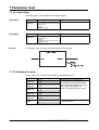
Pulse module
The two pulse modules convert continuous output signals into switching pulses.
[PulseMod1],
[PulseMod2]
Parameter
Selection/settings
Explanation
Cycle time
[CycleTim]
1 — 999.9s
20.0s
0 — 60s
0.0s
Cycle time of the switching pulses.
On/off time
[TOn/Off]
This parameter defines the minimum
length of the pulse which is output,
and also the minimum pause which is
made between pulses.
Used to protect the actuators
A defined output for the event of a
faulty input signal
Replacement 0 — 100%
value
0%
[ReplVal]
k = factory setting [ ] = short name in the controller operating unit
Function
The diagram shows the input and output signals of the function.
3.98/ JUMO mTRON controller operating unit
55
7 Parameter level
Block structure
for 1-setpoint
controllers
The block structure shows the internal processing of the signals and the influence of
the parameters for single-setpoint controllers.
Block structure
for 2-setpoint
controllers
The block structure shows the internal processing of the signals and the influence of
the parameters for double-setpoint controllers.
56
3.98/ JUMO mTRON controller operating unit
7 Parameter level
Block structure
for modulating
and actuating
controllers
The block structure shows the internal processing of the signals and the influence of
the parameters for modulating controllers, and for 2-setpoint controllers with an integral actuator driver.
XSh - Contact spacing (dead band)
v Section 7.1.8 “Controller parameters”
3.98/ JUMO mTRON controller operating unit
57
7 Parameter level
7.1.10 Mathematics
Two analogue input values can be combined in a mathematical formula.
Parameter
Selection/settings
Min. limit
[MinLimit]
-1999 to +9999
-1999
Max. limit
-1999 to +9999
[MaxLimit]
9999
Formula
Difference (a - b) [Diff]
[Formula]
Humidity (a : wet, b : dry)
[Hum]
Ratio (a/b) [Ratio]
Square root (a) [Root]
Square (a) [Square]
Minimum (a, b) [Minimum]
Maximum (a, b) [Maximum]
Absolute value (a) [Absolut]
Sum (a + b) [Sum]
Product (a ⋅ b) [Product]
Average (a, b) [Average]
AnIn1_Meas [0]
Input 1
[SelInput1]
AnIn2_Meas [1]
Exter_In [2]
Setpoint [3]
Ramp [4]
Controller Y1 [5]
Controller Y2 [6]
Input 2
AnIn1_Meas [0]
[SelInput]
AnIn2_Meas [1]
Exter_In [2]
Setpoint [3]
Ramp [4]
Controller Y1 [5]
Controller Y2 [6]
Replacement Limitation to limits [Limit]
value strategy Out-of-Range [OutRnge]
[ReplVStrat]
Explanation
Limits for the replacement value
strategy
Mathematical function
Humidity measurement by the
psychrometric method
Variable a
Variable b
Limitation to limits:
The output signal is limited to the limits
or, in the event of a faulty input signal,
is set to Out-of-Range.
Out-of-Range:
If limits are exceeded, the output
signal is set to Out-of-Range.
k = factory settting
58
[ ] = short name in the controller operating unit
3.98/ JUMO mTRON controller operating unit
7 Parameter level
Function
The diagram shows the input and output signals of the function.
Block structure
The block structure shows the internal processing of the signals and the influence of
the parameters.
Error handling
If an input is in the Out of Range condition, then “Out of Range” will be signalled to the
output.
7.1.11 Limit comparator
The limit comparator is used to monitor the difference between two input values for
going above/falling below a limit value or range.
Parameter
Parameter
Selection/settings
Explanation
Input 1
[SelInp1]
No function [0]
Input value 1
Controller_X [1]
Setpoints [2]
Ramp [3]
AnIn1_Meas [4]
AnIn2_Meas [5]
Controller_Y1 [6]
Controller_Y2 [7]
Exter_In [8]
Maths [9]
k = factory setting [ ] = short name in the controller operating unit
3.98/ JUMO mTRON controller operating unit
59
7 Parameter level
Parameter
Selection/settings
Explanation
Input 2
[SelInp2]
No function [0]
Controller_X [1]
Setpoints [2]
Ramp [3]
AnIn1_Meas [4]
AnIn2_Meas [5]
Controller Y1 [6]
Controller Y2 [7]
Exter_In [8]
Maths [9]
Comparator [Comp]
Window discriminator [WDis]
Comparator reversed
[CompRev]
Window discriminator
reversed [WDisRev]
0 — 9999
1.000
Input value 2
Function
[Function]
Hysteresis
[Hysteresis]
Replacement
value
[ReplVal]
Limit value
[LimitVal]
Off [Off]
On [On]
Defines the function of the limit
comparator
Difference between the relays
switching from ON to OFF and
OFF to ON
Switching state of the output in the
event of faulty communication
-1999 to +9999
Defines the switching level(s) of the limit comparator
0.000
k = factory setting [ ] = short name in the controller operating unit
Function
The diagram shows the input and output signals of the function.
Block structure
The block structure shows the internal processing of the signals and the influence of
the parameters.
60
3.98/ JUMO mTRON controller operating unit
7 Parameter level
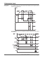
A selection can be made between four different limit comparator functions.
Comparator
Comparator
reversed
Window
discriminator
Window
discriminator
reversed
I1 - Input 1
I2 - Input 2
3.98/ JUMO mTRON controller operating unit
61
7 Parameter level
7.1.12 Control output conversion
The function is used to implement a cascade control.
Parameter
Selection/settings
Explanation
Add-in
[AddIn]
No function
The Add-in parameter has the effect
[NoFunct]
that the setpoint or the actual value is
added to the normalised control
Setpoint [Setpt]
output of the master controller.
Process value [ProcVal]
Setpoint start -1999 to +9999
Output signal for 0% controller output
[SetptStart]
0.000
Setpoint end -1999 to +9999
Output signal for 100% controller
[SetptEnd]
output
100.0
k = factory setting [ ] = short name in the controller operating unit
Function
This function is used for the scaling of Controller Y1, so that a slave setpoint can be
passed to a slave controller. The signal Add-in Y is output via the network.
The diagram shows the input and output signals of the function.
With the default settings this function is the same as the signal from Controller Y1 for
operating actuators.
Block structure
62
The block structure shows the internal processing of the signals and the influence of
the parameters.
3.98/ JUMO mTRON controller operating unit
7 Parameter level
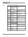
7.1.13 Analogue output
Input values are converted to physical output signals at the analogue output.
Parameters
Parameter
Selection/settings
Explanation
Conversion
start
[ConvStart]
-1999 to +9999
0.000
Input signal which corresponds to the
low range limit of the physical output
signal
Conversion
end
[ConvEnd]
-1999 to +9999
100.0
Input signals which corresponds to the
high limit of the physical output signal
Signal mode
[SignalMode]
0 — 20 mA [0/20mA]
4 — 20 mA [4/20mA]
0 — 10 V [0/10V]
2 — 10 V [2/10V]
0 — 100.0%
0%
Determines the physical output
signal
Replacement
value
[ReplVal]
Input
[SelInput]
Output signal in fault condition
Controller Y1 [0]
Input signal
Controller Y2 [1]
AnIn1_Meas [2]
AnIn2_Meas [3]
AnOut_In [4]
Maths [5]
k = factory setting [ ] = short name in the controller operating unit
Function
The diagram shows the input and output signals of the function.
Block structure
The block structure shows the internal processing of the signals and the influence of
the parameters.
3.98/ JUMO mTRON controller operating unit
63
7 Parameter level
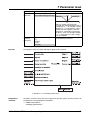
7.1.14 Logic output
Switching signals can be produced at two logic outputs.
[LogicOut1]
Parameter
Selection/settings
Explanation
Input
[SelInput]
Pulse 1 [0]
Signal source
Pulse 2 [1]
LC [2]
LogOut_In [3]
k = factory setting [ ] = short name in the controller operating unit
[LogicOut2]
Parameter
Selection/settings
Explanation
Input
[SelInput]
Pulse 1 [0]
Signal source
Pulse 2 [1]
LC [2]
LogOut_In [3]
k = factory setting [ ] = short name in the controller operating unit
Function
The diagram shows the input and output signals of the function.
7.1.15 Combination alarm
Various signals can be combined to produce a combination alarm.
Parameter
Selection/settings
Explanation
LC
[SelInput1]
yes [1]
Combination alarm produced [1]
no [0]
No combination alarm produced [0]
AI1_alarm
yes [1]
Alarms and warning alarms of measu[SelInput2]
no [0]
rement inputs AI1 and AI2 can
produce a combination alarm signal.
yes [1]
AI2_alarm
[SelInput3]
no [0]
AI1_warning
yes [1]
[SelInput4]
no [0]
AI2_warning
yes [1]
[SelInput5]
no [0]
0 — 255s
The combination alarm can be delayed
Delay time
by the preset time.
[Delay]
90s
k = factory setting [ ] = short name in the controller operating unit
64
3.98/ JUMO mTRON controller operating unit
7 Parameter level
Function
The diagram shows the input and output signals of the function.
Block structure
The block structure shows the internal processing of the signals and the influence of
the parameters.
In addition to the network variables which can be selected, the input networkvariables are monitored for communication errors or Out-of-Range condition (invalid
value).
With both errors a combination alarm will always be produced.
v System Manual 70.4010, Section 6.2 “Response to faulty communication”
7.2 Controller operating unit
7.2.1
Module
A characteristic module name for the task of the module in the process simplifies work
with the system.
Parameter
Module name
System number
[SystemNo]
Selection/settings
Operating unit
1 — 255
1
Explanation
Name of the module (16 characters)
The system number is valid for all modules of a system. It is transferred to
other modules during installation.
Module number
1 — 127
The module number differentiates the
[ModNo]
modules
of a system and has to be
127
entered only when, for example,
several operating units are operated in
one system.
k = factory setting [ ] = short name in the controller operating unit
3.98/ JUMO mTRON controller operating unit
65
7 Parameter level
7.2.2
Process windows
Parameter
Scroll time
[ScrollTim]
Selection/settings
0 — 255s
5s
Explanation
The process windows appear
cyclically in sequence for the preset
time.
0s
Scroll function is switched off
k = factory setting [ ] = short name in the controller operating unit
v Section 6.1 “Sequence of the process windows”
7.2.3
Alarm windows
Alarm windows signal alarm states which are defined by the user and which have to
be be eliminated (e.g overrange).
Parameter
Repeat time of
alarm indication
[ReIndAlarm]
Selection/settings Explanation
0 — 65535s
After aknowledging an alarm window, the
preset time elapses until the alarm message
60s
is indicated again, as long as the alarm
condition still exists, no other keys are
operated and no acknowlegement occurs.
0s
Repeat indication is switched off
No function [0]
Alarms are acknowledged only by key.
Acknowledge
LogicIn1
[1]
Alarms
are acknowledged by key, or via the
[SelAckn]
preset
HW
input.
LogicIn2 [2]
k = factory setting [ ] = short name in the controller operating unit
v Section 9.1 “Alarm windows”
7.2.4
Display
The display can be adapted to its surrounding using the following settings.
Parameter
Language
[Language]
Contrast
[Contrast]
Switch-off time
Selection/settings
Deutsch [Deutsch]
English [English]
Francais [Francais]
0 — 100%
50%
[OffTime]
1 — 999s
60 s
Display dark
0s
No function [0]
[SelDispDrk]
Explanation
One language is selected from the 3
device languages. The language alters
the dialog with the user, but not the system-specific designations, such as
the module name, for example.
LCD contrast against the background
After the last key stroke, the back-lighting remains switched on for the
preset time, after that it goes out.
If a key is pressed again, it lights up
afresh.
No time switch-off
The back lighting can not be switched
off.
The back lighting can be switched off
via the selected HW input.
LogicIn1 [1]
LogicIn2 [2]
k = factory setting [ ] = short name in the controller operating unit
66
3.98/ JUMO mTRON controller operating unit
7 Parameter level
7.2.5
Logic input
2 logic inputs enable external access to the functions of the controller operating unit.
[LogicIn1],
[LogicIn2]
Parameter
Characteristic
Selection/settings
Direct [Direct]
Explanation
When the switch is closed, the logic level is “1”.
[Charistic]
Invers [Reversd]
When the switch is closed, the logic level is “0”.
k = factory setting [ ] = short name in the controller operating unit
2 logic inputs can be connected via floating contacts. They can be used to operate
functions in the controller operating unit.
v Data Sheet 70.4045
Functions
-
Key inhibit via e.g. the key switch
-
Level inhibit against unauthorised access
v Section 7.27 “Inhibits”
-
LCD back-lighting on/off
v Section 7.2.4 “Display”
-
Acknowledgment of alarms
v Section 7.2.3 “Alarm windows”
7.2.6
Logic output
The logic output can produce an external alarm signal and operate a hooter, for
example.
Parameter
Characteristic
[Charistic]
Selection/settings
Direct [Direct]
Reversed [Reversd]
Explanation
The logics level remains unchanged
The logics level is reversed
Cycle time
0 — 100s
The cycle time (CycleTim) consists of
the switch-on time and the switch-off
time.
[CycleTim]
0
k = factory setting
No pulse response
[ ] = short name in the controller operating unit
3.98/ JUMO mTRON controller operating unit
67
7 Parameter level
Parameter
Switch-off time
[OffTime]
k = factory setting
Selection/settings
0 — 100s
1s
Explanation
Switch-off time of the logic output
[ ] = short name in the controller operating unit
The combination alarm is available as logic output (5V 40mA) at the connectors 3 and
4. It can be used e.g. to produce a hooter or a warning signal.
v Data Sheet 70.4045
Pulse response
68
Using the two parameters “Cycle time” and ”Switch-off time”, a pulse response can
be set at the logic output in order to operate a hooter, for example.
3.98/ JUMO mTRON controller operating unit
7 Parameter level
7.2.7
Inhibits
Inhibits are used to safeguard against unauthorised access via the controller operating
unit.
Parameters
Parameter
Inhibits
[SelKeyInh]
Process level
inhibit
[SelPrLvInh]
Logic_In1
Logic_In2
[1]
[2]
Parameter level
No function
[0]
Logic_In1
Logic_In2
Logic_In3
Logic_In4
Password
[1]
[2]
[3]
[4]
[5]
No function
[0]
Logic_In1
Logic_In2
Logic_In3
Logic_In4
Password
[1]
[2]
[3]
[4]
[5]
inhibit
[SelParLInh]
Installation level
inhibit
[SelInstInh]
Password
[Password1]
[Password2]
[Password3]
[Password4]
k = factory setting
Functions
Selection/settings
No function
[0]
Logic_In1
[1]
Logic_In2
[2]
No function
[0]
0000
0001 — 9999
Explanation
Keys can not be inhibited
Keys can be inhibited via the
selected HW input
The alteration of the process values
can not be inhibited.
The alteration of the process values
can be inhibited via the selected
HW input
The parameter level can not be
inhibited.
The parameter level can be inhibited
via the selected HW input
No function
The parameter level can be inhibited
via a password.
The installation level can not be
inhibited.
The installation level can be inhibited
via the selected HW input.
No function
The installation level is inhibited via a
password.
4-character password
[ ] = short name in the controller operating unit
Protection against incorrect operation and unauthorised access.
v Chapter 3 “Mounting in position”
3.98/ JUMO mTRON controller operating unit
69
8 Installation
At the installation level, the modules are selected with which the controller operating
unit is supposed to communicate.
8.1
Installation level
Menu selection
P > 2 sec
Use o or u to select installation level
Acknowledge with E
Use o or u to select “Automatic installation”, “Manual installation” or
✱ Press
✱
✱
✱
“Modules wink”
Automatic
installation
All mTRON modules which are connected to the bus are automatically identified and
added to the system.
✱ Acknowledge with
E (start of the installation)
The controller operating unit then carries out a reset (RESET) .
After a reset the module names may appear to have changed, because the
controller operating unit designates new names if module names are duplicated.
Module names can, however, be changed at any time
v Section 7.1.1 “Module”
Manual
installation
Only those instruments are added to the system whose installation key has been pressed on the module.
✱ Acknowledge with E (N blinks)
✱ “Set as “Y” with o, or leave as “N”
✱ Acknowledge with E
The number of controllers is indicated
(with “Y” it is set to the current value):
✱ Acknowledge with E
70
3.98/ JUMO mTRON controller operating unit
8 Installation
✱ Press installation key on one of the modules
✱ Press installation key on all modules which are to be added to the system
✱ Use P to quit the installation level
The controller operating unit then carries out a reset (RESET).
Modules “wink”
✱ Select “Modules wink” in the menu selection
✱ Using o or u select the required module name
(The selected module reacts instantly, without acknowledgment)
Controller modules and communication modules react with a blinking service LED.
Operating units display the message “Wink received”.
8.2
The module number is the instrument address for addressing the module
via the Modbus-RTU protocol.
v System Manual 70.4040 Part 9
Operating several installations in one bus system
If several installations are to be operated in one bus system, they must have different
system numbers.
Each controller operating unit must have a unique system number set up,
before the remaining modules are installed.
v Section 7.2.1 “Module”
3.98/ JUMO mTRON controller operating unit
71
8 Installation
8.3
Operating an installation with several operating units
If an installation is to incorporate several controller operating units, then they must
have different module numbers.
72
The module numbers of the controller operating units must be set before installing the remaining modules.
v Section 7.2.1 “Module”
3.98/ JUMO mTRON controller operating unit
9 Current alarms
9.1
Alarm windows
Calling an
alarm
At the alarm level, alarms are indicated and acknowledged.
The alarm level can be accessed
1. instantly after a new alarm has occured,
2. after the repeat time for alarm indication has elapsed,
3. manually via the menu selection “Current alarms”.
v Section 5.2 “Operating levels of the controller operating unit”
In the first case, the latest alarm is indicated first, all other alarms in ascending order
(arranged according to the module).
Acknowledgment
The indicated alarms are acknowledged in sequence with E , afterwards they are no
longer indicated until the time for repeat display has elapsed. If the conditions for the
alarm still exist, then the alarm window reappears automatically.
After all alarms windows have been acknowledged, the process windows are displayed again.
As well as by key, the alarm windows can be acknowledged via the logic inputs. In this
case, all alarms are acknowledged simultaneously.
v Section 7.2.3 “Alarm windows”
Logic output
The logic input is activated on all alarm windows, apart from the warning alarm.
9.1.1 Range monitoring
All controller measurement inputs are subject to a continuous range monitoring. If this
results in an alarm or warning alarm, the following alarm windows are displayed on the
controller operating unit.
v Section 7.1.2 “Analogue input”
An alarm appears at the top right of every alarm window.
Warning alarm/
alarm
3.98/ JUMO mTRON controller operating unit
73
9 Current alarms
Out-of-Range
Out-of-Range (measurement error) is produced in the event of going above /below the
sensor measurement range, as well as on sensor break or short-circuit.
The limits depend on the sensor which has been set.
9.1.2 Controller failure
During operation
The controller operating unit monitors all controller modules continuously for their
functions during operation. If a failure occurs, the following alarm is output:
on “Reset”
On reset/restart of the controller operating unit, the number of functional controllers is
compared with the number of controllers installed. If there is a deviation, the following
alarm is output once:
H
74
This alarm does not result in a repeat display.
3.98/ JUMO mTRON controller operating unit
10 Key combinations
At this level, the key combinations for “Installation”, “Reset” and “Wink” are
displayed. The key combinations for “Reset” and “Installation” are needed for
the installation. “Wink” is used to identify other modules.
Reset
A reset of the operating unit is always required after configuration of the system or system parts by the JUMO mTRON-iTOOL project design software
and subsequent transfer to the system (downloading).
✱ Press
P+E
simultaneously
Installation
key
If the P + o keys are pressed simultaneously on the controller operating unit,
it sends an identification message.
Receiving a
“Wink”
message
If a “Wink” message is sent from another controller operating unit to this operating unit, then it responds with the following display:
✱ Acknowledge the “Wink message” with any key.
3.98/ JUMO mTRON controller operating unit
75
11 Current module data
Parameter level
At this level, version number, measurement values and function outputs of all modules
of a system can be displayed. Selection and presentation of the parameters are
factory-set for each module type.
H
Selecting
parameters
This level only displays values!
Alterations can be carried out at the parameter level or in process windows.
The parameters of all modules can be accessed uniformly via a 2-step hierarchy:
1. Select mTRON-module
2. Select parameter
1. At present, no system error is defined (“0” is displayed).
2. “Combination alarm” corresponds to the logics level of the logic output
76
3.98/ JUMO mTRON controller operating unit
12 Specific module conditions
12.1 Action after a power failure
After a power failure the controller operating unit performs a normal re-start.
v Section 5.2 “Operating levels of the controller operating unit”
12.2 Action on errors of communication
If a module to which there is no longer any connection, or which has failed is addressed, then the controller operating unit shows the following response:
-
Next to the module name, the message “No contact” appears at the parameter and
module data levels.
-
The process variables of the module which can not be accessed are shown with
the replacement display: “---------” (value has not yet been transferred).
v Section 12.4 “Display of symbols”
-
In the case of a controller module, an alarm is produced
v Section 9.1.2 “Controller failure”
12.3 Action on faulty installation
Identical network
address
If, on a re-start or after “Reset”, the controller operating unit finds several modules
with identical network address, “Address error XX” is displayed, XX being the module
number which is present several times.
Different
module number
If, after a re-start or after “Reset”, the controller operating unit identifies a greater or
smaller number of controller modules as installed, the alarm “Controller No.: Error” is
produced.
v Section 9.1.2 “Controller failure”
Check installation or re-install it.
v Chapter 8 “Installation”
12.4 Display of symbols
Replacement
display of
numbers
Symbols
Meaning
+++++
Value invalid (Out-of-Range)
-------
Value not yet transferred
********
Value does not fit into the preset format (not enough places)
?????
Variable can not be shown
3.98/ JUMO mTRON controller operating unit
77