1
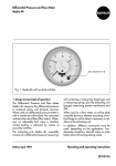
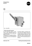
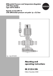
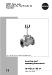
Differential Pressure
and Flowmeter
Media 04
Fig. 1 ⋅ Media 04
1. Design and principle of operation
The Media 04 Differential Pressure and Flowmeter is used for measuring the differential
pressure in industrial plants and building services. When used in conjunction with an orifice plate as differential pressure pick-up, the
instrument indicates the flow rate.
Edition March 1993
The Media 04 Indicating Unit consists essentially of the differential pressure cell with
measuring diaphragm and measuring
spring, and the indicating unit with pointer
mechanism and scale. For application as
flowmeter in addition to the indicating instrument, an orifice plate assembly (orifice flange
or orifice tube) is necessary.
Mounting and operating instructions
EB 9538 E
1
Differential pressure cell
1.1
1.2
1.3
1.4
1.5
1.6
1.7
1.8
Housing
High pressure head
Low pressure head
Spring plate
Measuring spring
Measuring diaphragm
Diaphragm plates
Diaphragm shaft
1.9
1.10
1.11
1.12
1.13
1.14
1.15
1.16
Guide springs
Connection link
Lever
Washer
Washer(s)
Screw
O-ring
Spring guide
2
Indicating unit
2.1
2.2
2.3
2.4
2.5
2.6
Rear cover
Closing cover
Regulating lever
Gear mechanism
Pointer
Zero adjustment screw
Fig. 2 ⋅ Top view section
The differential pressure ∆p = p1 – p2 creates
a force on the measuring diaphragm (1.6),
which is balanced by the measuring spring
(1.5). The deflection of the diaphragm (1.6)
and the lever (1.11), which is proportional to
2
the differential pressure, is transferred from
the pressure cell to the flexible washer (1.12)
and is transmitted to the pointer mechanism
via the adjusting lever (2.3).
therefore, it must be kept to a minimum and
must be considered when adjusting zero.
The dimension “K” (compensating height,
schematic 2) may be selected to suit the installation conditions.
2. Installation
2.1 Indicating unit
At the point of installation, fasten the instrument to the pipe, wall or mounting plate free
of vibrations. For mounting on a vertical or
horizontal pipe, use the mounting device with
clamp; for wall mounting, use mounting device without clamp (see dimension drawing,
section 6).
For panel-mounting (panel cut-out Ø114,
hole circle Ø120 mm) unscrew closing cover
and fasten rear cover with measuring cell to
panel as shown in the dimension drawing on
page 8.
2.2 Differential pressure lines
The differential pressure lines should have
tubes with an external Ø of 12 mm. The installation should be carried out according to
Fig. 3. Proper arrangement is absolutely
necessary. Pipe runs that would normally be
installed horizontally should be mounted with
a steady slope of not less than 1:20, i.e. sloping downward from the point that allows
venting.
The minimum bending radius shall not be less
than 50 mm.
Before the differential pressure lines are connected to the instrument they shall be flushed
thoroughly.
Make sure that the high-pressure line connects to the high-pressure connection and the
low-pressure line to the low-pressure one.
We recommend that both a shut-off valve
and also an equalizing valve be installed in
each differential pressure line. They are used
to shut off the two differential pressure lines
and short-circuit the lines at the indicating
unit for checking zero.
Attention: For connecting the differential
pressure lines, cutting ring connections are
necessary. Moreover, the free process fluid
connections of the differential pressure cell
must be closed by screw or vent plugs (see
section 5).
If the indicating unit is used for level measurement in vessels (Fig. 3), it must be arranged
below the liquid level to be measured. The
pressure line for the higher pressure must be
connected to the high-pressure chamber of
the indicating unit.
In liquid level measurements according to the
bottom left-hand schematic 1, the additional
hight “z” is included in the measurement;
M
h
z
K
= Measuring range
= Measured height
= Additional height
= Compensating height
z
h
H
H
H
h
h
Shut-off valve
Equalizing valve
K
-
+
Measurement on pressure vessels with condensating or non-condensating pressure cushion
+
-
Measurement on open vessel
with submerged ammeter
+
Measurement with cryogenic
plants (liquefied gases)
Fig. 3 ⋅ Installation schematics, e.g. liquid level measurement
3
2.3 Differential pressure pick-up (orifice
flange or orifice tube for flow measurement)
Before installing the differential pressure
pick-up, make sure that the pipeline upstream
and downstream of the standard orifice runs
properly. For she straight part of pipeline behind the orifice a length of 5 D suffices (D is
the internal pipe diameter). The required
length of the straight pipe run upstream of the
orifice depends on the aperture ratio “m”
and should amount to approximately L =
(130 m + 5) D.
The aperture ratio m =
d2
D2
4. Correcting zero
If shut-off and equalizing valves are installed
in the differential pressure lines, the zero
point can also be checked when the system is
being operated.
First, close shut-off valve in the low-pressure
line, then open equalizing valve and close
shut-off valve in the high-pressure line.
The pointer (2.5) must be positioned at zero.
Otherwise, adjust the zero adjustment screw
(2.6) until the zero position is reached.
To place into service, first open the shut-off
valve in the high-pressure line and then close
the equalizing valve. Finally, open the shutoff valve in the low-pressure line.
where d is the orifice diameter.
The high-pressure tap is to be located upstream of the orifice whereas the low-pressure tap is to be downstream of the orifice.
The sharp edge of the standard orifice must
be on the orifice inlet side, directed against
the medium flow (Fig. 4). The differential
pressure lines (copper tube 12 x 1) are to be
installed with a constant downward slope
from the differential pressure pick-up.
The indicating unit, therefore, should be arranged below the pipe to ensure that air inclusions can escape into the pipeline.
+
d
_
D
Fig. 4 ⋅ Orifice plate position
3. Start-up
Check zero point prior to start-up. If necessary, correct it at the zero adjustment screw
(2.6). Then slowly open the shut-off valves to
fill the system, so that the air in the diaphragm chambers can escape.
4
4.2 Measuring span — measuring range
The measuring span of the differential pressure flowmeter is determined by the differential pressure cell (three versions, different
measuring diaphragms (1.6) and guide
spring (1.9)) on the one hand, and by the
measuring spring (1.5) installed on the other
hand. The version of the measuring diaphragm and guide spring is printed on the
name plate.
The instrument is set by the manufacturer to
the measuring range specified in the order,
and the measuring range can be changed
subsequently only within the range permitted
by the measuring spring installed.
The measuring span can be adjusted continuously up to 60 % of the maximum measuring
span.
When a different span is to be adjusted, the
measuring spring (1.5) must be exchanged.
See instrument name plate and the table on
page 5.
turning it counterclockwise and downward a
little bit away from the center of motion of the
toothed segment.
Correct the zero point at the zero adjustment
screw (2.6) and apply again full load to the
measuring cell until the pointer shows 100 %.
Check the upper measuring range value at
the pressure gauge. Should it deviate from
the desired measuring range, repeat adjustment procedure as described above until
zero point and upper range value are correct.
Should the measuring range be changed
considerably, the zero point may drift out of
its adjustment range. In this case, try to adjust
the mid-value of the adjustment range by
turning the zero adjustment screw. Then,
remove pointer using a suitable pulling-off
device and reinstall it on the shaft at the position “Zero”.
4.2.1 Adjusting and changing the measuring range (Figs. 2 and 5)
Adjustment should preferably be made on
the test bench.
Unscrew the casing front section.
Adjust zero point at zero adjustment screw
(2.6).
Apply a pressure to the high-pressure side of
the measuring cell until the pointer indicates
full scale output 100 %. Read off the pressure
value at the checking pressure gauge (corresponds to the adjusted upper measuring
range value); then remove pressure.
If the measuring range is to be changed, the
black adjusting lever (2.3) is to be displaced
at the flattened point of the plastics part by
turning it either clockwise or counterclockwise (see Fig. 5).
If e.g. a wider measuring range is desired,
the adjusting lever (2.3) is to be moved by
Fig. 5 ⋅ Measuring range
adjustment
Measuring cell
1
Diaphragm 0.4/52
Guide spring 0.5
2
Diaphragm 0.4/70
Guide spring 0.8
3
Diaphragm 0.6/70
Guide spring 0.8
Measuring range (mbar)
Measuring spring
min.
max.
Wire-Ø
mm
Length
±0,1 mm
Order-no.
0 to 40
0 to 60
0 to 100
0 to 160
0 to 250
0 to 400
0 to 60
0 to 100
0 to 160
0 to 250
0 to 400
0 to 600
1.2
1.2
1.8
2.25
2.5
2.8
34.4
32.7
32.2
32
31.9
31.7
1400-5871
1400-5872
1400-5873
1400-5874
1400-5875
1400-5876
0 to 250
0 to 400
0 to 600
0 to 1000
0 to 400
0 to 600
0 to 1000
0 to 1600
2.25
2.5
3
3.4
32.4
32.2
31.8
31.6
1400-5879
1400-5880
1400-5881
1400-5882
0 to 1600
0 to 2500
3.6
31.6
1400-5885
Part
Designation
Order-no.
1.13
1.15
Washers
O-ring 22 x 2 — ECO
1400-5653
8421-0080
5
4.2.2 Changing the measuring range by exchanging the measuring spring
(Figs. 2 and 6)
Adjustment is to be made on the test bench
only.
If the measuring range is to exceed that of the
built-in measuring spring, the measuring
spring required shall be selected from the
table on page 7. Only the springs suiting the
existing measuring cell (see name plate) can
be exchanged. Proceed as follows:
Unscrew closing cover (2.2) and set zero
point with adjusting screw (2.6). Loosen
screws (1.14) and remove the spring plate
(1.4), spring guide (1.16), measuring spring
(1.5) and washer(s) (1.13) from the lowpressure side of the measuring cell. Install a
new spring (1.5) and fasten spring plate with
two screws (1.14). Check zero point, correct
deviation by installing washers of different
thickness (for oder number, see table on
page 7). For this purpose, the spring plate
must be removed each time. When zero point
is obtained, screw on the spring plate firmly;
check O-ring (1.15) for proper position and
replace, if necessary.
Adjust the measuring range as described in
paragraph 4.2.1.
Note on oxygen versions (O2)
Instruments for oxygen measurement are
provided with a label:
Oxygen! Keep free from oil and grease!
These versions have been assembled by the
manufacturer under special conditions and
have been washed afterwards.
Use suitable gloves when exchanging parts
which have contact with oxygen (e.g.
measuring springs).
6
Fig. 6 ⋅ Measuring range spring
5. Connection accessories
The instruments are delivered without process
fluid connections. Required cutting ring connections, screw and vent plugs or throttles for
damping of any oscillations caused by the
measured medium (especially for gas measurement) must be ordered separately.
Number
Designation
Order-no.
Standard
Rinsed for O2
2
Connections for tube 12 Ø, steel
1400-5842
1400-5843
2
Connections for tube 12 Ø, Niro
1400-5844
1400-5845
2
Connections for tube 10 Ø, steel
1400-5846
1400-5847
2
Connections for tube 8 Ø, steel
1400-5860
1400-5861
2
Connections for tube 12 Ø, with throttle, steel
1400-5848
1400-5849
2
Connections for tube 8 Ø, with throttle, steel
1400-5850
1400-5851
2
Connections for tube 6 Ø, with throttle, steel
1400-5852
1400-5853
2
Connections with throttle (special version for
measurement of liquefied gas)
—
1400-5858
2
Vent plugs, brass, with gaskets
1400-5654
1400-5658
2
Screw plugs, brass, with gaskets
1400-5655
1400-5659
1
Screw plug (half set), brass, with gasket
1400-5662
1400-5663
4
Gaskets
1400-5660
1400-5661
1
Mounting device for tube mounting
1400-5656
7
SAMSON AG ⋅ MESS- UND REGELTECHNIK
Weismüllerstraße 3 ⋅ D-60314 Frankfurt am Main
Postfach 10 19 01 ⋅ D-60019 Frankfurt am Main
Telefon (0 69) 4 00 90 ⋅ Telefax (0 69) 4 00 95 07
EB 9538 E
S/C 08.94
6. Dimensions in mm