1
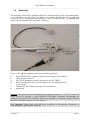
HV-TR150 User Manual _________________________________________________________________________________________________________________ 4. Technical Data Electrode output: floating current source, output impedance >1012 Maximum current: 1.25 µA into 100 M load Output current polarity: selected by +/0/- toggle switch Output current amplitude: selected by 10-turn potentiometer or analog input Modes of operation: set by two toggle switches or TTL signal CONT. / GATE switch enables manual or TTL gated operation AMP. / HV. switch connects the recording/application electrode output to amplifier’s headstage or to HV-TR150 current source output Display: current: XXXX nA Analog input: sensitivity 100 nA / V, Rin > 100 k, range ±10 V Current monitor: sensitivity 100 nA / V, Rout = 250 , not isolated Voltage monitor: VEL / 10, Rout = 250 , not isolated Size: Headstage size: front panel 12 HP (60.6 mm) x 3U (128,5 mm), 7” (175 mm) deep 65x25x25 mm EPMS-07 SYSTEM Dimensions: Power Requirements: 115/230 V AC, 60/50 Hz, fuse 2 A / 1 A, slow, 45-60 W (dependent on the modules plugged in) 19” rackmount cabinet, 3U high (1U = 1 3/4” = 44.45 mm) ___________________________________________________________________________ version 1.8 page 12