1
HV-TR150 User Manual
_________________________________________________________________________________________________________________
3.4.
Description of the Front Panel
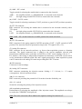
Figure 4: NV-TR150 front panel view
(1) CURRENT nA display
3 ½ digits display showing the amplitude of the injection current. The current that is set with
potentiometer #12 or via analog IN connector is always displayed, even if actually no current
flows (because the AMP. / HV. switch #3 is in AMP. position). This allows first to set the
desired current amplitude and then to activate the current flow.
(2) AMP. / HV. LEDs
LEDs indicating which module is connected to the electrode (when operating in combination
with an amplifier module using the same electrode).
AMP.:
HV.:
the amplifier module, e.g. BA-01M, is connected to the electrode.
the high voltage module HV-TR150 is connected to the electrode.
___________________________________________________________________________
version 1.8
page 7