1
HV-TR150 User Manual
_________________________________________________________________________________________________________________
3.5.
Headstage
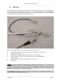
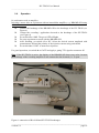
The headstage is housed in a small box that can be mounted directly onto a micromanipulator.
It is connected to the HV-TR150 by means of a shielded flexible cable and a multi-pole
connector, and it is connected to the headstage of the recording amplifier, e.g. BRAMP-01R
using a shielded flexible cable and a BNC connector.
Figure 5: HV-TR150 headstage with electrode holder (optional)
1
2
3
4
5
6
ELECTRODE: BNC connector for the electrode holder, driven shield
GND: ground connector
HV-TR150 headstage connector and cable to the HV-TR150
BNC connector and cable to the headstage of the recording amplifier,
e.g. BA-01M
OPERATE LED: indicates that injection current flows
holding bar
Caution: The current injection headstage has an output compliance of ±125 V if switch #3,
Figure 4 is in HV. position, i.e. if the OPERATE LED lights. In addition, all headstages are
equipped with sensitive FET amplifiers that can be damaged by electrostatic charge and must
therefore be handled with care (see also chapter 1).
Very Important: Always turn power off when connecting or disconnecting headstages or
when changing or adjusting the electrodes.
___________________________________________________________________________
version 1.8
page 9