1
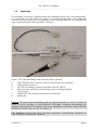
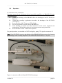
HV-TR150 User Manual _________________________________________________________________________________________________________________ 3.6. Operation In combination with an amplifier Injecting a tracer after an experiment with an intracellular amplifier, e.g. BRAMP-01R using continuous current Connect the headstage of the BRAMP-01R to the headstage of the HV-TR150 (see Figure 6) Connect the recording / application electrode to the headstage of the HV-TR150 (see Figure 6) Set switch #3 to AMP. The green LED #2 lights Do your experiment as usual with the BRAMP-01R After finishing, set switch #3 to HV. Select the desired current amplitude with potentiometer #12 and the polarity of the injection current using switch #11 Set switch #4 to CONT. to start tracer injection. For gated operation, set switch #4 to GATE and apply a gating TTL signal to connector #5. Note: If the HV-TR150 is active, the display of the BRAMP-01R shows any value, because the headstage of the recording amplifier is not connected to the electrode, i.e. is open. Figure 6: connection of BA-01M and HV-TR150 headstages ___________________________________________________________________________ version 1.8 page 10