1
HV-TR150 User Manual
_________________________________________________________________________________________________________________
(3) AMP. / HV. switch
Toggle switch for selecting the module that is connected to the electrode.
AMP.:
HV.:
the amplifier module, e.g. BRAMP-01R, is connected to the electrode.
the high voltage module HV-TR150 is connected to the electrode.
(4) CONT. / GATE. switch
Toggle switch for selecting continuous (CONT. position) or gated (GATE position) operation.
(5) TTL IN connector
BNC connector for selecting the module that is connected to the electrode remotely with a
TTL signal.
HI:
the high voltage module HV-TR150 is connected to the electrode
LOW:
the amplifier module, e.g. BRAMP-01R, is connected to the electrode.
Note: AMP. / HV. switch #3 must be in AMP. position for remote selection!
(6) TTL IN connector
BNC connector for the gating signal in GATED operation (CONT. / GATE. switch in GATE
position. The injection current is generated as long as the TTL signal is HI (+5 V).
(7) Analog IN connector
BNC connector for an external waveform, e.g. from a data acquisition system or a function
generator. The signal connected here is added to the current amplitude selected with
potentiometer #12 and can be used either in GATED or CONT. mode. Scaling: 100 nA / V.
For instance, when using as independent iontophoresis instrument, a RETAIN current can be
set by potentiometer #12 and switch #11, and a signal generated by a data acquisition system
can be connected to the analog IN connector providing the EJECT current.
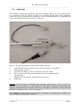
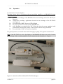
(8) HS connector
Connector for the headstage.
(9) Analog OUT connector
BNC connector monitoring the injection current. Scaling: 1 V / 100 nA, i.e. 1 V output
corresponds to 100 nA injection current.
(10) VEL:10 connector
BNC connector providing the potential in Volt at the electrode divided by ten.
(11) +/0/- switch
Switch for selecting the polarity of the injection current.
(12) Amplitude potentiometer
Potentiometer for selecting the amplitude of the injection current. The amplitude can always
be read at the CURRENT nA display #1.
Note: The value selected at #12 is added to the signal at Analog IN connector #7.
___________________________________________________________________________
version 1.8
page 8