1
10 Technical specifications
10 Technical specifications
11 Spare parts
Designation
Miniature fuses, type 5 x 20 mm, 1.5 A slow.
The product will be replaced in case of an Automatic
Door Control Unit defect.
Enclosure
Housing type
Height
Width
Depth
Weight without
packaging
Potential equalisation
Earthing
Protection category
Interfaces
LED display
Door outputs
Normally closed
contacts
Operational area
Temperature
Humidity
Storage temperature
Rated voltage
Fuses
Automatic Door Control
Unit
Plastic coating with metal
trim
1 U (44.5 mm)
136 mm
129 mm
approx. 0.6 kg
- 1)
- 1)
IP 40 according to
EN 60529
2x, Power Control
4x, Doors Status
4x, max. 24 V DC, 400 mA
4x, max. 30 V DC, 1 A
+5° to +45°C
+42° to +113°F
5 – 95%
-20° to +60°C
-4° to +140°F
1 x 24 V DC,
2.0 A SELV
1.5 A miniature fuse, slow,
UL approval
2 x RJ-12 sockets
EN
12 Wiring diagrams
A Word template for creating circuit diagrams can be
downloaded from the RITTAL homepage
www.rittal.com. This template allows all products of
the CMC-TC system to be represented and
integrated in circuit diagrams.
13 Glossary
CMC: Computer Multi Control
CMC-TC: Computer Multi Control – Top Concept
CU: Control Unit (Automatic Door Control Unit)
PU II: Processing Unit II
14 Customer service addresses
If you have technical questions, or
questions regarding our product range,
please contact the following service contact:
Tel.: +49 (0)2772/505-1855
http://www.rittal.com
E-mail: [email protected]
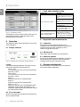
CMC-TC connection
Maximum cable length
CU to I/O unit
10 m, after consultation
with Rittal, up to 50 m,
UL approval
CU to Basic CMC
10 m, after consultation
with Rittal, up to 50 m,
UL approval
CU to LCP Plus
10 m, after consultation
with Rittal, up to 50 m,
UL approval
1)
Not required because 24 V DC safety extra-low voltage
Automatic Door Control Unit
9