1
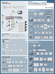
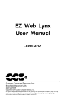
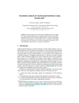
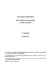
Operating Instructions ZI 1293 /. . . Multi-Zone Control Unit USA 05/07 Info Z 6 / HK 6.1 Contents 01. Introduction 3 02. Special features 3 03. Technical data 3 04. Range of the control units ZI 1293 /. . . 4 05. Electrical connection 05.1 Pin diagram for ZI 1293 /. . . 5.2 Assignments of Zones - Plug 5 5 5 06. Start-up 06.1 Functions of the keys and displays 6 6 07. Description of the displays and keys 07.1 Description of keys 07.2 Alarm displays 7 7 7 08. 8.1 8.2 8.3 08.4 08.5 8.6 08.7 Settings Activating control zones Deactivating control zones Set value settings Changing of settings Selector mode Reset of factory settings Soft Start 8 8 8 9 9 10 11 11 09. Menu points 12 10. Connector pin assignment 13 11. Replacing fuses 14 12. Safety instructions 15 2 1. Introduction The HASCO multi-zone controller ZI 1293 / . . . provides clear display of all SET and ACTUAL values. These are divided into groups of 6 zones. 2. Special Features 쐽 쐽 쐽 쐽 쐽 쐽 쐽 쐽 쐽 쐽 6 unit sizes are offered : 6, 12, 18, 24, 30 and 36 control circuits. Modular construction providing 3200 W per control circuit. Programmable soft start. Standard alarm input and output. Manual or automatic change to selector mode. Programmable setting for short-term temperature increase. Temperature stand by mode Performance display in Ampere and % selector ratio. Thermocouple monitoring Syncronized heat-up The control unit ZI 1293 /. . . corresponds to the important protection requirements in agreement with the EU guidelines. The Control unit ZI 1293 /. . . also corresponds to the important protection requirements following the UL (USA) and CSA (Canada) guidelines. 3. Technical data ZI 1293 / 6 /... ZI 1293 / 12 /... ZI 1293 / 18 /... ZI 1293 / 24 /... ZI 1293 / 30 /... Outside dimensions (W x H x D) Device fuse protection Connected voltage Power output Thermocouple Operating range Control accuracy Ambient temperature Alarm control outputs Alarm outputs Power fuse Degree of protection ZI 1293 / 36 /... 350 x 200 x 400 350 x 380 x 400 32 A / Phase 3 phases 120VAC / 60 Hz, L1-L3 = black / white / red 3200 W / zone ( max. 19 kW ) Fe-Cu Ni, Typ J 122 . . . 932°F ± 2 °F (at optimum conditions) 50 . . . 104°F 2 Switch inputs 2 relay changeover contacts max. 33 VAC / 70 VDC FF 16 / 500 IP 21 (EN 60529) 3 4. Range of the control units ZI 1293 /. . . ZI 1293 / 6 / 16 6 Control circuits ZI 1293 / 12 / 16 12 Control circuits ZI 1293 / 18 / 16 18 Control circuits ZI 1293 / 24 / 16 24 Control circuits ZI 1293 / 30 / 16 30 Control circuits ZI 1293 / 36 / 16 36 Control circuits 4 5. Electrical connection The power and thermocouple linkage between mold and control unit ZI 1293 /. . . is made with a seperate power cable ZI 1222 /. . . and TC cable ZI 1223 /. . . . The following must be adhered to when using all ZI 1293/. . . temperature control zones : The maximum power input of 19 kW must not be exceeded! 5.1 Pin diagram for ZI 1293 /. . . (Examples) e.g. ZI 1293/6x16 1 2 3 4 5 6 7 8 9 10 11 12 13 14 15 16 17 18 19 20 21 22 23 24 1 2 3 4 5 6 7 8 9 10 11 12 13 14 15 16 17 18 19 20 21 22 23 24 Load + - TC e.g. ZI 1293/12x16 1 2 3 4 5 6 7 8 9 10 11 12 13 14 15 16 17 18 19 20 21 22 23 24 1 2 3 4 5 6 7 8 9 10 11 12 13 14 15 16 17 18 19 20 21 22 23 24 Load + - TC Allocation of pin connection according to DIN 16765 5.2 Assignments of Zones - Plug Load Zone 1, 13, 25 2, 14, 26 3, 15, 27 4, 16, 28 5, 17, 29 6, 18, 30 7, 19, 31 8, 20, 32 9, 21, 33 10, 22, 34 11, 23, 35 12, 24, 36 TC PIN 1 / 13 2 / 14 3 / 15 4 / 16 5 / 17 6 / 18 7 / 19 8 / 20 9 / 21 10 / 22 11 / 23 12 / 24 Zone 1, 13, 25 2, 14, 26 3, 15, 27 4, 16, 28 5, 17, 29 6, 18, 30 7, 19, 31 8, 20, 32 9, 21, 33 10, 22, 34 11, 23, 35 12, 24, 36 PIN 1+ / 132+ / 143+ / 154+ / 165+ / 176+ / 187+ / 198+ / 209+ / 2110+ / 2211+ / 2312+ / 24- 5 6. Start-up Connect T/C and power cables to mold. Check with Volt / Ohm meter to make sure power and T/C cables are connect. Plug cables into controllers. Switch control unit On at the main switch at the back. Set the set temperature. Make sure that unused control zones are switched off (see page 8). The control unit now heats the mould evenly, moist heating elements are dried out. During this time, the temperature deviation alarm displays blinks in all active zones. The temperature in ºF is shown in the zone window. In the switched-off control zones the display shows “OFF”. After reaching the set temperature, production can start with the calculated parameters. If failures occur during start-up, then the cause of the failures can be recognized by the corresponding displays at the individual zones (see page 7). 6.1 Function of the keys and displays Alarm displays Dialog window A Key Set value A A Set value display, Power-regulation ratio display A Actual value display A Key Scroll A Zone window heating impluse display Key Temperature Boost Key Load current (A), Power-regulation ratio display P A Key Programming abort / zone off ESC PRG I Key Up / Down Key Programming / Enter Key Manuell Key Temperature Lowering 6 7. Description of the displays and keys 7.1 Discription of keys Key display lights up when operated (function On). Set value The set point values appear in the zone windows or “OFF” in the non-active zones. P A Load current (A) / power regulation ratio (%) The actual load current (A) / power regulation ratio (%) appears in the active zone windows. Boost function active Temperature is raised for a short period. Same function via external alarm-communication connection-cable. Lowering active Temperature is permanently lowered. Same function via alarm plug. 7.2 Alarm displays Thermocouple Lights up if thermocouple is broken and ”- - -” appears in the zone window. If the automatic selector mode (Automode) is active, then the display alternates between ”- - -” and ”- A -”. The display blinks up for reverse poling and the room temperature appears in the zone window. Temperature deviation It is flashing during the heating phase of the soft start ramp. In addition, the current load are double-side disconnected for over temperature (max exceeding of set value). Current overload Lights up when the set maximum current is exceeded (see change set values) or for missing load. For current overload the load are double-side disconnected. 7 8 Settings 8.1 Activating control zones Key Command Display Display set temperature The set temperatures are displayed in the zone windows or “OFF” in the inactive zone. The key display lights up. Select zone The selected zone number is displayed in the dialog window. Confirm zone “TEMP” is displayed in the dialog window, the set values in the zone windows blink to be altered. Storing The selcted zone is activated. Set temperature Off The actual temperatures are displayed in the zone windows or “OFF” in the inactive zones. Key display “Off”. Control operation. Abort without storing : Abort Goes back one programming step without changing the set values. 8.2 Deactivating control zones Key Command Display Display set temperature The set temperatures are displayed in the zone windows or “OFF” is displayed in the inactive zones. Select zone The selected zone number is displayed in the dialog window. Confirm zone “TEMP” is displayed in the dialog window, the set point values flashes in the zone windows to be altered. Deactivate zone Press key for 3 sec. till “OFF” is displayed in the zone windows. Store deactivating Press key again. Set temperature Off The actual temperatures are displayed in the zone windows or “OFF” is displayed in the inactive zones. Key display Off. Control operation. Abort without storing : Abort Goes back one programming step without changing the set values. 8 8.3 Set value settings Key Command Display Display set temperature The set temperatures are displayed in the zone windows or “OFF” in the inactive zones. The key display lights up. Select zone The selected zone number is displayed in the dialog window; ALL for all zones. Confirm zone “TEMP” is displayed in the dialog window, the selceted windows flash (ALL for all). Setting the set value The changed set values are displayed. Storing The changed set points are accepted and shown in the zone window. The dialog display is turned off. Set temperature Off The actual temperatures are displayed in the zone windows or OFF in the inactive zones. Key display Off. Control operation. Abort without storing: Abort Goes back one programming step without changing the set values. 8.4 Changing of settings Key Command Display longer than 5 sec. Change settings “ALL” is displayed in the dialog window. The zone numbers are displayed in the zone windows. Select zone The selected zone number is displayed in the dialog window and ALL for all zones. Confirm zone The first menu point appears in the dialog window. The actual temperatures are displayed in the zone windows or “OFF” for the inactive zones. Select menu point The respective menu point is displayed in the dialog window. Confirm menu point The current set point values blink in the zone windows to be changed or for same set values for all zones. Only the middle zone window above the dialog display flashes. Change settings The changed settings are shown flashing. Storing The changed settings are accepted. Exit set mode Dialog display is deleted, the actual temperatures are displayed in the zone windows or OFF in the inactive zones, normal operation. Abort without storing: Abort Goes back one programming step without changing the set values. 9 8.5 Selector mode Key Display CAUTION: The hotrunner block is not controlled In this operating state and will not switch off for over temperature. Therefore, overheating and destruction of the hotrunner block is possible! Command Display set value The set values appear in the zone windows or ”OFF” in the inactive zones. The key display lights up. Select zone Set the desired zone for the actuator operation. Manual operation is only possible for individual zones! Confirm zone "PULS" appears in the dialog window. Set load In percent (P 01… P100 = 1… 100 %). Confirm setting The set value is accepted. Set value display Off The display of the manually operated zone is alternatively ”P” for (pulse operation) and the actual current value (for a defective thermocouple ”- - -”). In the zone windows without manual operation, the actual values are displayed or ”OFF” for the inactive zones. The set manual operation is reset by switching off the device at the main switch! Abort without storing: Abort Goes back one programming step without changing the set values. 10 8.6 Reset of factory settings Key Command Display longer than 5 sec. To change settings Press and hold the “PRG” key for 5 seconds then the dialog window displays “ALL” and zone numbers appear in the zone windows. To select zone The selected zone number appears in the dialog window and “ALL” is displayed for all zones. To confirm zone The first menu point appears in the dialog window. The actual temperatures are displayed in the zone windows or OFF is displayed for the inactive zones. Select menu point The respective menu point is displayed in the dialog window. Choose PRESET Confirm menu point The dialog window display alternates between "PRESET” and ”OK?” Storing The settings are reset at work. Exit set mode Dialog display is deleted, the actual temperatures are displayed in the zone windows or OFF in the inactive zones, normal operation. Abort without storing : Abort Goes back one programming step without changing the set values. 8.7 Soft Start After switching on the controller, the temperature increases to the set soft start temperature of ramp 1 (rE = 248°F). After reaching this temperature, the dwell time rt is activated (for 1 minute). This is permitting any residual moisture in the heating elements to escape. Ramp 2 The 2nd ramp r2 starts once the dwell time rt has expired for all activated control zones. The temperature then increases to the set value for production run. Set temperature +Ot -Ut rt r2 rE = 248°F r1 11 9. Menu points Menu points Display At works Over temperature switch point (Ot) Settings Value range OVTEMP 50 °F 32 . . . 122 °F above set value Under temperature switch point (Ut) U N T E M P 50 °F 32 . . . 122 °F below set value Final temperature ramp 1 (rE) RMPEND 248 °F 248 . . . 320 °F Temperature rise ramp 1 (r1) RMP T1 2 °F / 4 s 2 °F /10 s … 2 °F / 2 s Temperature rise ramp 2 (r2) RMP T2 2 °F / 2 s 2 °F /10 s … 2 °F / 2 s Dwell time of the final temperature ramp 1 (rt) RMPPSE 2 min. 0 … 4 min. AUTO 0 (Off) 1 = On 0 = Off Automatic selector mode Temperature decrease (Operating time min 15 minutes!). For active function, after thermocouple break, heating is continued with the average output performance of the past 15 minutes. 122 °F 50 . . . 392°F below set value below set value TC TYP J J or L Temperature unit UNIT °F °F or °C Reset of in-plant settings PRESET - - All changed settings could be reset of in-plant settings Software Version of the Control Card FW VER - V ... Shows Software version Access code / input lock CODE 0 (deactivated) 0 - 250 Deactivate ramp synchronisation SYNC 1 (On) 1 = On 0 = Off Thermocouple selection type J or type L TEMPDN Remarks The following functions can be set individually for each zone Raising the boost temperature TEMPUP 68 °F 41 . . . 140°F Duration of the boost process UPTIME 20 s 0 …180 s CURR 16 A 1 …16 A TMPMAX 842 °F 122 . . . 932°F Over current switch point Set value limit 12 10. Connector pin assignment Controller alarm Alarm output of the controller (potential-free normally open contact) Connection from controller to injection molding machine Alarm outputs 1 = overtemperature 2 = undertemperature Ö M S max. 50 V/ 2 A PIN Description 1 2 3 6 7 8 Ö -Alarm M -Alarm S -Alarm S -Alarm M -Alarm Ö -Alarm 1 1 1 2 2 2 (OVTEMP) (OVTEMP) (OVTEMP) (UNTEMP) (UNTEMP) (UNTEMP) Temperature reduction Alarm output of the injection molding machine Connection from injection molding machine to controller Alarm inputs 1 = temperature reduction 2 = boost normally open contact PIN Description 04 + 05 10 + 12 E1-Reduction E2-Boost 13 11. Replacing fuses Working on the unit may only be carried out by authorized technicians, before opening unplug the unit. To change the fuses please open front panel and disconnect plugs. Pull the concerned control card. Replace of fuses only with a same type! The control cards are designed for 6 zones in each case, allocation see below. Assembly in reversed order. Allocation zones / control cards Card 1 Card 2 Card a b c d e f g h Fuses Control Cards i j k l 6 5 4 3 2 1 Zone Card Fuse Zone Card Fuse 1 2 3 4 5 6 7 8 9 10 11 12 13 14 15 16 17 18 1 1 1 1 1 1 2 2 2 2 2 2 3 3 3 3 3 3 a+b c+d e+f g+h i+j k+l a+b c+d e+f g+h i+j k+l a+b c+d e+f g+h i+j k+l 19 20 21 22 23 24 25 26 27 28 29 30 31 32 33 34 35 36 4 4 4 4 4 4 5 5 5 5 5 5 6 6 6 6 6 6 a+ b c+d e+ f g+ h i+j k+l a+ b c+d e+ f g+ h i+j k+l a+ b c+d e+ f g+ h i+j k+l 14 12. Safety instructions 쐽 HASCO-connecting cables and connecting housings are to be used for the electrical connections (power and thermocouple connections) between control unit and the mold. This will ensure optimum controlling accuracy. 쐽 The control units are matched to the HASCO range of standard elements. No guarantee can be given for trouble-free functioning if components of foreign brands are used. 05 07 1 i / No. 102316 쐽 Connection, repair and maintenance work may only be carried out by trained electrical technicians. 쐽 During work on the control units and the linked cables, devices, machines and tools, all parts must be disconnected from the mains. The system must also be safeguarded from being unintentionally turned on again. 쐽 HASCO-connecting cables must be regularly checked for mechanical damage and replaced as necessary. 쐽 The devices must be located such that sufficient ventilation and cooling is available. 쐽 The controllers must be protected from moisture and wet. 쐽 The devices must be applied in a technically meaningful way. 쐽 Unplug the unit when replacing the fuse. 쐽 From a unit size of ZI1293/ 18/ 16 it is recommended to clean the dust filter once a while resp. to replace it depending on operating period and condition. 쐽 Furthermore the cooling ribs of the unti should be checked and if necessary removed from contamination. This may only be carried out by authorized service people. Alterations reserved © by HASCO D-58505 Lüdenscheid 쐽 When changing fuses the plug must be pulled out. HASCO Hasenclever GmbH + Co KG · D-58505 Lüdenscheid · Tel. (0 23 51) 95 70 · Fax (0 23 51) 95 72 37 · www.hasco.com · [email protected]