1
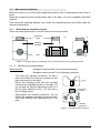
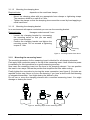
3.2
Electrical Connection
Complete the mechanical installation before you connect the device electrically.
Set up all electrical connections while the voltage supply is switched off.
M12 circular connector
3-wire circuitry
cable gland
transmitter
3-wire circuitry
n.c.
(-)
(+)
n.c.
2
1
6
ϑ
ϑ
Figure 5: Variants of electrical connection
Route the cable so that it does not apply force or torque to the measuring insert.
For devices with field housing, hold the housing with the other hand when you screw or
unscrew the field housing cap.
4
Operation
During device operation, take care that the device remains within its intended temperature
range. No other monitoring is necessary.
Permissible media temperature:
-40…150 °C
Permissible ambient temperature:
-40…100 °C
When supplied with a transmitter, the permissible ambient temperature is reduced to 85°C.
Restricted ambient conditions may apply in explosion protected environments (see
XA_001).
4.1
Calibration
We recommend an annual recalibration.
Uninstall only the measuring insert. This way the measuring position remains unchanged
as it is defined by the clamping element.
During calibration you must not exceed 100 °C at the electrical connector due to inside
gaskets. If your device is equipped with an integrated temperature transmitter you must
not exceed 85 °C at the housing.
Apply new heat conductive paste when you reinstall the measuring insert after the
calibration. This ensures a good and constant thermal coupling between insert and pipe.
For further details please consult the separate calibration guideline for the Clamp-on family
(TA_008).
BA_049 Rev 1L3 Resistance Thermometer Clamp-on technology
Page 5/6