1
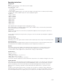
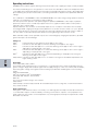
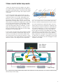
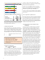
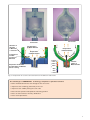
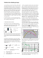
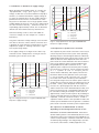
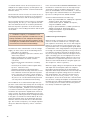
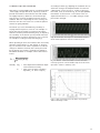
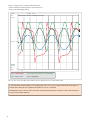
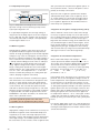
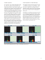
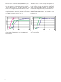
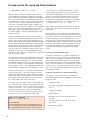
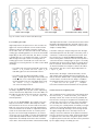
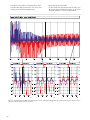
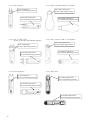
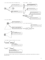
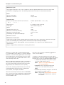
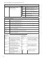
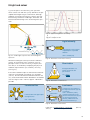
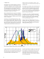
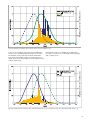
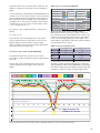
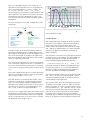
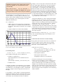
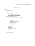
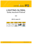
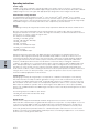
ECG
Luminaire
US
Lamp
Fig. 13: Simplified circuit diagram showing the electronic operation of high intensity discharge lamps
Voltage in V
Current in A
Time in ms
Fig. 14: Current and voltage of a metal halide lamp
operated on a rectangular electronic ballast
For a conventional ballast, it can be presumed that the
service life is defined by the choke temperature tw. A
10 °C increase in the tw temperature means that the
service life is halved.
In electronic ballasts, these circumstances are far
more complicated. The mortality rate of individual components, the circuit design and above all the electronic
load and the temperatures at which the units are operated have a considerable influence on the service life
behavior.
This is why the nominal service life of electronic
ballasts is stated in combination with a failure probability. For example, all units in the product family
POWERTRONIC® PTi have a nominal service life of
40,000 hours with failure probability of maximum
10% when operated at the maximum permissible
temperatures.
The service life of electronic ballasts is influenced
directly by the temperature at which the units are operated. This is why 2 temperature values are defined
to describe the thermal behavior. The ambient temperature ta describes the temperature immediately
surrounding the unit and thus prevailing around the
electronic components. To be clear, this is not the
room temperature or the ambient temperature of the
luminaire.
When an electronic ballast is fitted in a luminaire, the
real ambient temperature ta of the ballast can only be
measured with great difficulty and at great effort. This
is why a second temperature has been stipulated: the
tc temperature. Basically this is the casing tempera-
ture which can be measured by a thermocouple at a
set point – the tc point – and is defined as maximum
permissible temperature at which safe operation of the
electronic ballast is still guaranteed. In addition, the tc
temperature is set in relation to the ballast service life.
That means that the measured tc temperature permits
very precise conclusions as to the anticipated service
life of the electronic ballast.
OSRAM’s HID electronic ballast for example principally
reaches its full nominal service life at the maximum
permitted tc temperature. In practice, this means
that any temperature levels below the t c temperature
always prolong the effective service life. As a rule of
thumb, it can be presumed that a temperature 10 °C
below the printed maximum tc temperature will double
the service life of the electronic ballast.
However, it is not advisable to use only the absolute
maximum tolerable tc value for conclusions regarding
the quality and service life of an electronic ballast. This
is because on the one hand, the position and therefore
indirectly also the value of the t c point can be freely
defined by every electronic ballast manufacturer. On
the other hand, the rule of stating the nominal service
life at the maximum permitted t c temperature has not
yet become established throughout the electronic
ballast industry. In practice this means that many
electronic ballasts only achieve approx. 50% of their
nominal service life at maximum tc temperature.
Nominal service life (B10): max. 10% of the
electronic ballasts have failed
A serious evaluation of the electronic ballast
service life is only possible by comparing the
electronic ballast ambient temperature t a with
the corresponding service life.
Comparison of the service life using only the t c
temperature is not appropriate.
3.2.3 Advantages of operation with electronic
ballast POWERTRONIC ® PTi
The following table provides an overview of the advantages of operating lamps with the electronic ballast.
The corresponding values and statements are based
on tests and experience with POWERTRONIC® PTi
ballasts, so that they cannot necessarily be transferred
1:1 to ballasts of other makes.
In comparing the conventional and the electronic
ballast, the performance of the conventional ballast
constitutes the reference parameter and is given a
value of 100. This is also based on the fact that the
lamp parameters are defined with the reference
conventional ballast.
For more details, please refer to the POWERTRONIC®
Technical Guide – Electronic control gears for metal
halide lamps.
13