1
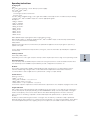
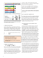
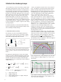
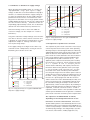
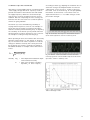
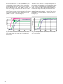
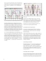
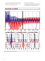
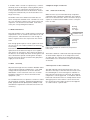
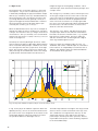
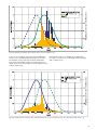
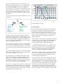
5 Reducing the wattage of high intensity discharge lamps
5.1 Introduction
5.2 Wattage reduction techniques
High intensity discharge lamps generate light by exciting mercury and other metals within an arc tube into
a plasma generated by the current flow between two
electrodes.
The following dimming methods are generally known
(by conventional means or electronic ballast):
• Reduction in supply voltage
• Phase control: leading edge, trailing edge
Discharge lamps must be operated with a ballast and
are rated for a certain lamp wattage. Either conventional chokes or electronic ballasts can be used.
• Increase in choke impedance or decrease in lamp
current (amplitude modulation)
• Change in frequency for high-frequency operation
To change the nominal lamp wattage of a lamp, the
following general physical conditions are significant for
the resulting effects:
• The electrodes of discharge lamps are rated for
a certain lamp current. If the current is too high,
parts of the electrodes melt and evaporate. If
the current is too low, the electrode is operated
in cold state. This changes the mechanisms for
releasing electrons from the electrode with more
electrode material being deposited on the tube
wall. Deviations in lamp current from the nominal value in both directions can therefore cause
blackening of the arc tube wall with a decline
in luminous flux, together with negative effects
on the light colour and possibly also on the service life.
• The partial vapor pressure of the filling particles
responsible for generating light depends on the
temperature of the arc tube wall. A change in
the arc tube wall temperature resulting from a
change in lamp wattage influences the composition of the filling in the plasma arc and thus the
electrical and photometric properties of the
lamp.
5.2.1 Reducing the supply voltage
A reduction in supply voltage beyond recommended
limits (see sections 3.1.2 and 3.1.3) will decrease the
lamp wattage. Reducing lamp wattage results in decreased lamp voltage and re-ignition peak voltage, and
is generally to a lesser extent than the supply voltage.
This reduction in the gap between the re-ignition peak
and the supply voltage makes it more probable that
the lamp will go out. This applies particularly to aged
lamps where the lamp voltage and re-ignition voltage
have already increased.
Fig. 25 shows, as an example, the behavior of certain
lamp types on reducing the supply voltage. Here the
ratio of re-ignition voltage to effective supply voltage
(ULS/US) has been standardized to 1 for 220 V supply
voltage. It can be seen that when the supply voltage decreases, this ratio generally assumes values of
greater than 1. This also means that the gap between
ULS/US referred to the ratio at 220 V
HCI-TM 250 W/WDL
HCI-TS 70 W/WDL
HCI-TT 150 W/WDL
HQI-TS 150 W/WDL
• At higher arc tube wall temperatures, the metals
do not recombine with the iodides and the pure
metals can migrate into the wall (applies to quartz
arc tubes).
• Drop in luminous flux through blackening
of thearc tube
• Change in color properties
• Reduction in service life
1,4
ULS/US referred to the ratio at 220 V
Wattage reduction has the following side effects:
HQI-TS 150 W/NDL
1,3
1,2
1,1
1
0,9
140 150 160 170 180 190 200 210 220 230 240 250 260
Supply voltage US in V
Fig. 25: Relative change in the re-ignition peak (ULS )
to supply voltage (US ) referred to the ratio at 220 V for
various metal halide lamps
23