1
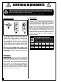
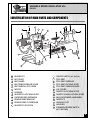
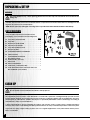
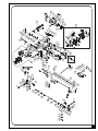
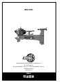
SETUP & OPERATION MANUAL FEATURES Quick lock control levers easily position tool rest. Large 12″ inboard bowl turning capacity. Stable cast-iron frame, head & tailstock to reduce chatter and vibration for smoother turning. “MAXI-LATHE VS+” 12″ X 17″ WOOD LATHE variable speed Maximum distance of 17 5⁄16″ between centers. Maximum distance of 49″ between centers with optional bed extension (Item #25205). Quick release belt tension lever for faster, easier speed changes. Three variable speed ranges: 300 to 900, 600 to 1800 & 1200 to 3600 rpm. Digital spindle speed display. 10″ tool rest with sturdy 1″ diameter support post. Forward/reverse switch. Features positive spindle indexing in 10° increments - total 36 index positions. SPECIFICATIONS SPINDLE SPEED (VARIABLE) 300 TO 3600 RPM SWING OVER BED 12″ (304 MM) SWING OVER TOOL REST 9 ¼″ (236 MM) SWING OVER SIDE BED 19 ¼″ (490 MM) SWING OVER SIDE TOOL REST 16 ⅝″ (424 MM) DISTANCE BETWEEN CENTERS 17 5⁄16″ (440 MM) SPINDLE THREAD 1″ (25.4 MM) - 8 TPI TAILSTOCK THROUGH HOLE ⅜″ (10 MM) MORSE TAPER MT #2 SELF EJECTING TRAVEL 2 ⅛″ (55 MM) MODEL #25-200 TOOL REST 10″ (254 MM) FACE PLATE 3″ (76 MM) INDEXING POSITION 36 X 10° MOTOR M1 ¾ HP, 110 V, 8 A, 2500 RPM WEIGHT 146 LBS (66.5 KG) VERSION 1_REVISION 6 - DECEMBER 20/12 © Copyright General® International 12/2012 GENERAL® INTERNATIONAL 8360 Champ-d’Eau, Montreal (Quebec) Canada H1P 1Y3 Telephone (514) 326-1161 • Fax (514) 326-5555 • www.general.ca THANK YOU for choosing this Variable Speed Maxi Lathe VS+ model 25-200 by General® International. This unit has been carefully tested and inspected before shipment and if properly used and maintained, will provide you with years of reliable service. To ensure optimum performance and trouble-free operation, and to get the most from your investment, please take the time to read this manual before assembling, installing and operating the unit. The manual’s purpose is to familiarize you with the safe operation, basic function, and features of this unit as well as the set-up, maintenance and identification of its parts and components. This manual is not intended as a substitute for formal woodworking instruction, nor to offer the user instruction in the craft of woodworking. If you are not sure about the safety of performing a certain operation or procedure, do not proceed until you can confirm, from knowledgeable and qualified sources, that it is safe to do so. Once you’ve read through these instructions, keep this manual handy for future reference. GENERAL® INTERNATIONAL WARRANTY All component parts of General® International products are carefully tested and inspected during all stages of production, and each product is thoroughly inspected upon completion of assembly. Because of our commitment to quality and customer satisfaction, General® International agrees to repair or replace, within a period of 24 months from date of purchase, any genuine part or parts which, upon examination, prove to be defective in workmanship or material. In order to obtain this warranty, all defective parts must be returned freight pre-paid to General® International Mfg. Co., Ltd. Repairs attempted without our written authorization will void this warranty. Disclaimer: The information and specifications in this manual pertain to the unit as it was supplied from the factory at the time of printing. Because we are committed to making constant improvements, General® International reserves the right to make changes to components, parts or features of this unit as deemed necessary, without prior notice and without obligation to install any such changes on previously delivered units. Reasonable care is taken at the factory to ensure that the specifications and information in this manual corres-ponds with that of the unit with which it was supplied. However, special orders and “after factory” modifications may render some or all information in this manual inapplicable to your machine. Further, as several gene-rations of this model of wood lathe and several versions of this manual may be in circulation, if you own an earlier or later version of this unit, this manual may not depict your tool exactly. If you have any doubts or questions contact your retailer or our support line with the model number of your unit for clarification. RULES FOR SAFE OPERATION To help ensure safe operation, please take a moment to learn the machine’s applications and limitations, as well as potential hazards. General® International disclaims any real or implied warranty and holds itself harmless for any injury that may result from improper use of its equipment. 1. Do not operate the wood lathe when tired, distracted, or under the effects of drugs, alcohol or any medication that impairs reflexes or alertness. 2. The working area should be well lit, clean and free of debris. 3. Keep children and visitors at a safe distance when the wood lathe is in operation; do not permit them to operate the wood lathe. 4. Childproof and tamper proof your shop and all machinery with locks, master electrical switches and switch keys, to prevent unauthorized or unsupervised use. 5. Stay alert! Give your work your undivided attention. Even a momentary distraction can lead to serious injury. 6. Fine particulate dust is a carcinogen that can be hazardous to health. Work in a well-ventilated area and whenever possible use a dust collector and wear eye, ear and respiratory protection devices. 7. Do not wear loose clothing, gloves, bracelets, necklaces or other jewelry while the wood lathe is in operation. Wear protective hair covering to contain long hair and wear non-slip footwear. 8. Be sure that adjusting wrenches, tools, drinks and other clutter are removed from the machine before operating. 9. Keep hands well away from the spindle, the spin ning workpiece, and all moving parts. Use a brush, not hands, to clear away chips and dust. 10. Do not use stock containing defects such as checks, splits, cracks, knots or foreign objects. Before starting, inspect stock and remove all foreign objects such as dirt, nails, staples or any object that could damage a tool or become dislodged and fly free and cause injury. 11. Select appropriate turning speed for the size and type of workpiece being turned and use lowest speed when starting a new workpiece. 12. Before turning on the wood lathe, make sure the workpiece is securely installed between centers and that all locking levers and moveable or removable parts are tightened down and secured. 13. Adjust the cutting tool parallel and as close as possible to the workpiece and, before starting the lathe, turn the workpiece by hand, at least one full rotation to make sure that it does not come in contact with the cutting tool. 14. Maintain turning tools with care. Keep turning tools sharp and clean for best and safest performance. 15. Avoid working from awkward or off balance positions. Do not overreach and keep both feet on floor. 16. Keep guards in place and in working order. If a guard must be removed for maintenance or cleaning be sure it is properly re-attached before using the tool again. 17. Use of parts and accessories NOT recommended by GENERAL INTERNATIONAL may result in equipment malfunction or risk of injury. 18. Never stand on machinery. Serious injury could result if the tool is tipped over. 19. Always disconnect the tool from the power source before servicing, changing accessories, performing any maintenance or cleaning, or if the machine will be left unattended. 20. Make sure that switch is in the “OFF” position before plugging in the power cord. 21. Make sure the tool is properly grounded. If equipped with a 3-prong plug it should be used with a three-pole receptacle. Never remove the third prong. 22. Do not use this wood lathe for any purpose other than its intended use. If used for other purposes, GENERAL INTERNATIONAL disclaims any real or implied warranty and holds itself harmless for any injury, which may result from that use. 3 ELECTRICAL REQUIREMENTS BEFORE CONNECTING THE MACHINE TO THE POWER SOURCE, VERIFY THAT THE VOLTAGE OF YOUR POWER SUPPLY CORRESPONDS WITH THE VOLTAGE SPECIFIED ON THE MOTOR I.D. NAMEPLATE. A POWER SOURCE WITH GREATER VOLTAGE THAN NEEDED CAN RESULT IN SERIOUS INJURY TO THE USER AS WELL AS DAMAGE TO THE MACHINE. IF IN DOUBT, CONTACT A QUALIFIED ELECTRICIAN BEFORE CONNECTING TO THE POWER SOURCE. THIS TOOL IS FOR INDOOR USE ONLY. DO NOT EXPOSE TO RAIN OR USE IN WET OR DAMP LOCATIONS. EXTENSION CORDS GROUNDING INSTRUCTIONS If you find it necessary to use an extension cord with your machine, use only 3-wire extension cords that have 3prong grounding plug and a matching 3-pole receptacle that accepts the tool’s plug. Repair or replace a damaged extension cord or plug immediately. A B C In the event of an electrical malfunction or short circuit, grounding reduces the risk of electric shock. The motor of this machine is wired for 110V single phase operation and is equipped with a 3-conductor cord and a 3-prong grounding plug A to fit a grounded type receptacle B. Do not remove the 3rd prong (grounding pin) to make it fit into an old 2-hole wall socket or extension cord. If an adaptor plug is used C, it must be attached to the metal screw of the receptacle. Note: The use of an adaptor plug is illegal in some areas. Check your local codes. If you have any doubts or if the supplied plug does not correspond to your electrical outlet, consult a qualified electrician before proceeding. CIRCUIT CAPACITY Make sure that the wires in your circuit are capable of handling the amperage draw from your machine, as well as any other machines that could be operating on the same circuit. If you are unsure, consult a qualified electrician. If the circuit breaker trips or the fuse blows regularly, your machine may be operating on a circuit that is close to its amperage draw capacity. However, if an unusual amperage draw does not exist and a power failure still occurs, contact a qualified technician or our service department. 4 Make sure the cord rating is suitable for the amperage listed on the motor I.D. plate. An undersized cord will cause a drop in line voltage resulting in loss of power and overheating. The accompanying chart shows the correct size extension cord to be used based on cord length and motor I.D. plate amp rating. If in doubt, use the next heavier gauge. The smaller the number, the heavier the gauge. TABLE - MINIMUM GAUGE FOR CORD TOTAL LENGTH OF CORD IN FEET 50 FEET 100 FEET AMPERE 110 VOLTS 25 FEET RATING -------> 6 TO 10 -------> 10 TO 12 -------> 12 TO 16 -------> <5 AWG 150 FEET 18 16 16 14 18 16 14 12 16 16 14 12 14 12 * NR * NR * NR = Not Recommended VARIABLE SPEED MAXI-LATHE VS+ 25-200 IDENTIFICATION OF MAIN PARTS AND COMPONENTS RPM SPEED / VITESSE TR/MIN 8.8.8.8. ON/OFFARRÊT EN MAR CHE/ MAX. MIN. Ù HEADSTOCK FACE PLATE BELT GUARD BELT TENSION RELEASE LEVER BELT TENSION LOCK LEVER MOTOR FLYWHEEL HEADSTOCK LOCKING LEVER OUTBOARD BED EXTENSION SPINDLE SPEED READOUT SPINDLE SPEED CONTROLLER HEADSTOCK PIVOT PIN ON/OFF SWITCH (KEY SWITCH) TOOL REST TOOL REST CARRIAGE TOOL REST LOCKING LEVER TOOL REST CARRIAGE LEVER LIVE CENTER TAILSTOCK LOCKING LEVER TAILSTOCK QUILL LOCKING LEVER QUILL MOVEMENT HANDWHEEL TAILSTOCK LEVELING FOOT LATHE BED FORWARD/REVERSE SWITCH (NOT SHOWN) 5 UNPACKING & SET UP UNPACKING This model 25-200 is heavy – 146 lbs (66.5 kg). Do not over-exert. The help of an assistant will be needed for the following step. Carefully unpack and remove the wood lathe and its components from the box and check for damaged or missing items as per the list of contents below. NOTE: Please report any damaged or missing items to your General International distributor immediately. LIST OF CONTENTS Once the parts have been removed from the packaging, you should have the following items: A H F B Qty A- TOOL REST LOCKING LEVER . . . . . . . . . . . . . . . . . . . .1 D E B- TOOL REST . . . . . . . . . . . . . . . . . . . . . . . . . . . . . . . . . .1 J C C- HEADSTOCK SPUR CENTER . . . . . . . . . . . . . . . . . . . . .1 D- TAILSTOCK LIVE CENTER . . . . . . . . . . . . . . . . . . . . . . .1 E- TOOL REST EXTENSION POST . . . . . . . . . . . . . . . . . . . .1 F- KNOCK OUT BAR . . . . . . . . . . . . . . . . . . . . . . . . . . . . .1 M G- OUTBOARD EXTENSION HARDWARE . . . . . . . . . . . . . .2 H- SAFETY GLASSES . . . . . . . . . . . . . . . . . . . . . . . . . . . . . .1 I- N G I L K OUTBOARD BED EXTENSION . . . . . . . . . . . . . . . . . . . .1 J- BELT TENSION LEVER . . . . . . . . . . . . . . . . . . . . . . . . . .1 K- LEVELING FEET (with nuts) . . . . . . . . . . . . . . . . . . . . . .4 L- FACE PLATE . . . . . . . . . . . . . . . . . . . . . . . . . . . . . . . . . .1 M- FACE PLATE WRENCH . . . . . . . . . . . . . . . . . . . . . . . . . .1 N- ALLEN KEYS (3 MM AND 6 MM) . . . . . . . . . . . . . . . . .1 O- LATHE WITH HEADSTOCK, TAILSTOCK AND TOOL REST CARRIAGE (NOT SHOWN) . . . . . . . . . . . . . . . . .1 CLEAN UP Be sure to work in a well ventilated area for the clean-up process. The unpainted cast-iron surface of the lathe bed is covered with a protective coating that helps prevent rust from forming during shipping and storage. Remove this protective coating by rubbing with a rag dipped in kerosene, mineral spirits or paint thinner. (Handle and dispose of potentially flammable solvent soaked rags according to manufacturers’ safety recommendations.) A putty knife held flat to avoid scratching the surface, may also be used to scrape off the coating followed by clean-up with solvent. Avoid rubbing the lathes painted surfaces as many solvent based products will remove paint. To prevent rust, apply a light coating of paste wax or use regular applications of any after-market surface protectant or rust inhibitor. 6 INSTALLATION & ASSEMBLY For your convenience this lathe is shipped from the factory partially assembled and requires only minimal assembly and set-up before being put into service. Before starting the assembly, make sure that the switch is in the “OFF” position and that the power cord is unplugged. Do not plug in or turn on the lathe until you have completed the assembly and installation steps described in this section of the manual. SPEED RPM / VITESSE TR/MIN 8.8.8.8. ON/OFFARRÊT EN MARCHE/ SPEED RPM / VITESSE TR/MIN 8.8.8.8. MAX. MIN. F ON/OF/ARRÊT EN MARCHE MAX. MIN. The unit should be installed on a flat, sturdy and stable surface able to support the weight of the machine and the workpiece with ease. Never install the machine over the edge of a table or workbench. Install the leveling feet and set the lathe on your workbench. Adjust the leveling feet to ensure that all four feet sit firmly on the bench. Make sure that the machine does not rock. If you prefer an optional steel stand (item 25195N) is available from your local General International dealer. The stand is equipped with mounting holes allowing the lathe, after removing the leveling feet, to be bolted directly to the stand. For your safety it is essential that the machine does not rock or tip during operation. Upon start-up or during operation, if you notice any rocking, tipping or chattering of the base turn the machine off immediately and re-adjust the leveling feet as needed to stabilize the lathe on the bench. If a permanent shop placement is practical, consider removing the leveling feet on the base and drilling matching through-holes in the mounting surface of your workbench or stand to bolt the lathe in place (hardware not included) on your workbench. A B C A. Lathe B. Hex head bolt C. Flat washer D. Workbench or stand E E. Flat washer F. Lock washer F D G G. Hex nut 7 SPEED RPM / VITESS 8.8.8 MIN. Top View A SPEED RPM / VITESS 8.8.8 MIN. C D B Release the headstock locking lever A and pull the headstock pivot pin B outwards and pivot the headstock 180º. Lock the headstock in place by pulling the headstock locking lever forward C. Side View Use the 2 mounting bolts and lock washers D to attach the outboard bed extension to the bed as shown. SPEED RPM / TR/MIN VITESSE 8.8.8.8. OFF RRÊT ON/HE/A EN MARC MAX. MIN. Install the belt tension release lever as shown. E F Install the tool rest on the tool rest carriage. TOP VIEW G Thread the face plate onto the headstock spindle E and tighten using the supplied face plate wrench (Insert the knock-out bar in the spindle hole F to keep the spindle from turning while tightening the face plate). 8 Then lock the face plate by tightening the two set screws G using a 3 mm Allen key. Install the supplied tool rest locking lever on to the tool rest extension post and set the post aside for use during outboard turning. BASIC ADJUSTMENTS & CONTROLS ON /OFF POWER SWITCH: The wood lathe is equipped with a rocker type ON/OFF switch located on the headstock A, that is equipped with a lock-out key. To prevent unwanted or unauthorized start-up or usage remove the lock-out key and store it in a safe place B. To start the lathe, insert the lock-out key and pull up the switch C.To stop the lathe, push down on the power switch D. Press DOWN to STOP B Pull UP to START C A D FORWARD / REVERSE SWITCH ALWAYS BE SURE TO STOP THE LATHE SPINDLE COMPLETELY BEFORE CHANGING DIRECTION. WHEN MOUNTING A FACE PLATE, ALWAYS MAKE SURE THE SET SCREWS IN THE FACE PLATE ARE TIGHTENED SECURELY AFTER THE FACE PLATE IS INSTALLED. FAILURE TO DO SO MAY RESULT IN THE FACE PLATE UNSCREWING FROM THE SPINDLE. The Forward/Reverse switch E is located on the rear of the headstock F. E F Forward: The spindle rotates toward to the operator from the top of the workpiece. Reverse: The spindle rotates backward to the operator from the top of the workpiece. 9 CHANGING SPINDLE SPEED: This model 25-200 MAXI-LATHE VS + is equipped with an electronic variable speed controller allowing the user to change the speed of the spindle (within the 3 different spindle speed ranges: 300-900, 600-1800 & 1200-3600 rpm) by simply turning the speed control dial. The digital spindle speed readout will indicate the operating spindle speed. Note: Turning speeds vary depending on the size and diameter of the workpiece as well as which stage you are at in the overall turning process. When turning a smaller diameter workpiece, a higher spindle speed is recommended. Proper spindle speed selection comes with practice and experience and when in doubt always start at a slower speed increasing when you are sure that it is safe to do so. SP EED REC O MMEN DAT ION S 3 SPEE D R ANGES DIAMETER OF WORK ROUGHING RPM GENERAL CUTTING RPM FINISHING RPM UNDER 2” 1500 2650 3600 2 TO 4” 800 1400 2000 4 TO 6” 800 1400 2000 6 TO 8” 800 1400 2000 8 TO 10” 300 700 1000 10 TO 12” 300 700 1000 Use the chart as a basic guideline for selecting the appropriate spindle speed. H High : 1200-3600 RPM Low : 300 to 900 RPM Medium : 600-1800 RPM M L Changing between the 3 speed ranges requires moving the drive belt from one set of drive pulleys to another. The speed range will vary. To reposition the belt and change spindle speed ranges: 1. Turn off and unplug the lathe from the power source. 2. To access the belt and pulleys, loosen the belt guard locking screw A and open the belt guard located on the headstock B. E L MH 5. Set the belt by hand to the required pulley position (High/Medium/Low) E. 10 C B A D 3. Release the belt tension locking lever C. 4. Release the tension on the belt by pulling the belt tension release lever backward D. F G 6. Push the belt tension release lever forward to re-tension the belt F and lock the belt tension lever G. 7. To verify the belt positioning and ensure the belt will run smooth on the pulleys; rotate the fly wheel A by hand to turn the spindle while observing the belt movement. If the belt moves smoothly re-install the belt guard – if the belt wobbles between the pulleys repeat steps 3-6 as needed. A TOOL REST CARRIAGE & TOOL REST ADJUSTMENTS: C B 1. The tool rest carriage can be moved along the bed slide ways as needed. Loosen the tool rest carriage lever B and move the carriage to the desired location. Re-tighten the lever securely after adjustment. 2. The tool rest should be adjusted so that its top is 1/8" above the center of the workpiece. Loosen the tool rest locking lever C and adjust the height and position of the tool rest as needed. Re-tighten the lever securely after adjustment. MOUNTING & REMOVING HEADSTOCK SPUR CENTER: E D 1. The headstock spindle has an MT#2 taper hole into which the spur center fits D. Make sure the shank of the spur center and the spindle hole are clean and free of debris, then fit the spur center firmly in the spindle hole by hand E. 2. To remove the headstock spur center, knock it out from the opposite end of the spindle using the supplied knock-out-bar. Note: When knocking out the spur center, always hold it by hand to prevent it from falling. MOUNTING & REMOVING TAILSTOCK LIVE CENTER: 1. The tailstock has an MT#2 taper hole into which the live center fits. Make sure the shank of the live center and the tailstock hole are clean and free of debris and fit the live center firmly in the spindle hole by hand. 11 2. To remove the live center from the tailstock quill, loosen the tailstock quill locking lever F and move the quill out by turning the quill movement handwheel G until the quill end is nearly inside the tailstock and the live center can be removed by hand. Note: When removing the live center, always hold it by hand to prevent it from falling H. Back View G H F MOVE TAILSTOCK QUILL IN/OUT: The tailstock quill can be moved in and out of the tailstock casting by turning the tailstock quill movement handwheel. Back View B Back View A 1. To move the tailstock quill, loosen the quill locking lever A. 3. Re-tighten the quill locking lever to secure the quill in its new position. 2. Turn the the quill movement handwheel B to move the quill as needed. TAILSTOCK MOVEMENT: The tailstock is used to support the other end of the workpiece to be turned and can be moved along the bed slideways to suit the length of the workpiece. To move the tailstock on the bed: A 1. Loosen the tailstock locking lever A. B 2. Move the tailstock by hand to the desired location on the bed. 3. Re-tighten the tailstock locking lever B to secure the tailstock in its new position. MOUNTING A WORKPIECE TO THE FACEPLATE: TOP VIEW For turning applications where the workpiece cannot be secured between the headstock and tailstock centers (such as bowl turning) the faceplate must be used to secure the workpiece to the headstock spindle. REMOVE THE FACE PLATE 1. Unlock the face plate by loosening and removing the two set screws A using a 3 mm Allen key. A B 2. Loosen the face plate by inserting the supplied knock out bar in the spindle hole to keep the spindle from turning while loosening the face plate using the supplied face plate wrench, as shown in B, then unscrew and remove the face plate. 12 3. With the face plate removed from the lathe, mount the workpiece onto the faceplate with wood screws (not included) through the mounting holes on the face plate. Make sure the screws are not so long that they will enter the area of the workpiece where the material is to be removed. 4. Re-install the face plate on the headstock. PIVOTING THE HEADSTOCK (FOR OUTBOARD TURNING): For outboard bowl turning on larger diameter work pieces the headstock can be pivoted 180° To pivot the headstock: C D A B 1. Loosen the headstock locking lever A. 2. Unscrew the knurled end of the indexing pin (turn counter clockwise) and pull out on the headstock pivot pin to release the headstock B. 3. Rotate the headstock 180° to outboard position. C and D. 4. Release the headstock pivot pin and re-tighten it (turn clockwise) on its shaft. 5. Adjust the positioning of the headstock on the bed and tighten the headstock locking lever to secure the headstock in place. CHECKING ALIGNMENT BETWEEN CENTERS: There is a small amount of play built into the headstock on the bed to allow the headstock to pivot freely. Whenever the headstock is pivoted back from the outboard position, the alignment between the headstock and tailstock centers should be double checked and adjusted as needed. To check the alignment between the headstock and tailstock centers: B C A 1. Pivot the headstock to its normal spindle turning position and lock it in place. 2. Install a spur center in the headstock and a live center in the tailstock. 5. Look down at the two centers from above to verify that the points are in alignment. If the points line up B, proceed with normal turning operations. 3. Release the tailstock locking lever and advance the tailstock on the bed A until the points of the 2 centers just barely touch each other. 6. If the points are not lined up release the headstock locking lever and manually adjust the headstock position using the play in the headstock to line up the center points C. 4. Using the tailstock locking lever, secure the tail stock on the bed with the points still touching. 7. With the points lined up, hold the headstock in place and tighten the headstock locking lever. 8. With the points lined up, proceed with normal turning operations. 13 PERIODIC MAINTENANCE • Keep the unit clean and free of dust by wiping with a cloth or vacuuming off any woodchips or dust after each use. • All bearings are sealed and permanently lubricated and no further lubrication is required. • Regular applications of any after-market surface protectant or rust inhibitor will help prevent rust and keep the tool rest, head, and tailstock sliding smooth on the bedway. • Always turn off and unplug the lathe when you have completed turning and to avoid unauthorized use, remove the switch key and store it in a safe place. • Periodically inspect the power cord and plug for damage. Replace the power cord and the plug at the first signs of visible damage. NOTES 14 RECOMMENDED OPTIONAL ACCESSORIES A large range of optional aftermarket accessories can be used with this lathe. Your local dealer may be able to offer suggestions based on what is readily available in your area. Key issues to keep in mind when shopping for aftermarket accessories are: Headstock and tailstock feature a MT#2 taper – to avoid damaging the lathe use only headstock and tailstock centers with a matching taper. Headstock spindle threads are 1” diameter x 8 threads per inch (T.P.I.) – to avoid stripping or damaging the threads, use only threaded headstock attachments (such as face plates and jaw chucks) that have matching threads. We also offer a large variety of optional accessories to help you increase productivity, accuracy and safety when using your lathe. Here’s a small sampling of accessories available from you local General International dealer. For more information about our products, please visit our website at www.general.ca Steel support stand for maxi-lathes - #25-195N Free-up valuable bench space in your shop and mount your lathe to dedicated stand. Easy to assemble. This sturdy steel stand is designed specifically to fit General International models 25100, 25-114, 25-114QC & 25-200 Maxi Lathes. STEEL SUPPORT STAND FOR MAXI-LATHE BED EXTENSIONS #25-196 For models: 25-100, 25-114, 25-114QC and 25200. #25-105 │ 4" - 4 JAW SCROLL CHUCK 1" - 8 4 Piece Woodturning Chisel Set - #25-210 Designed specifically for use on lathes with 1” dia. x 8 TPI headstock threads. Made from hi-speed steel this kit comes in it’s own wooden carrying case and features 4 of the most commonly used turning tools including a 3/4” parting tool, a 1/2” round nose scraper, a 1” skew chisel and 1/2” bowl gouge. 32″″ BED EXTENSION (FOR 49 5⁄16″″ BETWEEN CENTERS) - #25-205 Portable Dust Collector - #10-050M1 Designed for flexibility and mobility. Featuring an adjustable multi-position support arm and a wide, rotating dust hood this unit is ideal for use on wood lathes. 15 PARTS LIST 25-200 IMPORTANT: When ordering replacement parts, always give the model number, serial number of the machine and part number. Also a brief description of each item and quantity desired 16 PART N0. REF. N0. DESCRIPTION SPECIFICATIONS QTY 25200-001 25200-002 25200-003 25200-004 25200-005 25200-006 25200-007 25200-008 25200-009 25200-010 25200-013 25200-017 25200-018 25200-019 25200-020 25200-021 25200-022 25200-023 25200-024 25200-025 25200-026 25200-027 25200-028 25200-029 25200-030 25200-031 25200-032 25200-033 25200-033-1 25200-033-2 25200-035 25200-036 25200-038 25200-039 25200-040 25200-041 25200-042 25200-043 25200-044 25200-045 25200-047 25200-048 25200-049 25200-051 25200-051-1 25200-051-2 910092-000 921457-000 006002-049 250372-615 380571-901 171960-902 000403-107 000104-111 090246-000 000203-102 000201-101 WN02-06 250589-000 171959-000 011001-105 000101-101 171961-901 003303-204 021102-000 009003-200 003303-207 021805-000 000205-101 030408-000 012003-007 WN02-53 050966-902 921458-000 380407-901 380443-906 240056-907 003201-101 030407-000 660114-000 380562-901 050719-000 006502-200 001901-103 014320-000 090167-000 380552-907 010209-000 130190-000 WN02-31 490468-000 250679-615 MOTOR DC90V/0.75HP LOCK LEVER 5/16"-18UNC-3/4"L FLAT WASHER 8.5 X 16 X 2t KNOB HANDLE MOTOR PLATE FLAT HEAD SCREW M6 X 1.0P X 16 CAP SCREW M8 X 1.25P X 35 MOTOR PULLEY SET SCREW M6 X 1.0P X 8 SET SCREW M4 X 0.7P X 6 POWER CORD WINDOW HEADSTOCK COVER SPRING PIN 3 X 10 CAP SCREW M4 X 0.7P X 8 SENSOR BRACKET ROUND HEAD SCREW 3/16"-24NC X 3/4" RELIEF ACC-2.5 NUT 3/16" X -24NC ROUND HEAD SCREW 3/16"-24NC X 5/8" STRAIN RELIEF NB-1216 SET SCREW M10 X 1.5P X 12 BEARING 6005-2NK KEY 5 X 5 X 20 SPINDLE FACE PLATE SPUR CENTER ASS'Y SPUR CENTER CENTER POINT FOR SPUR CENTER SPINDLE FLYWHEEL SET SCREW 1/4"-20NC X 1/4" BEARING 6004-2NK MAGNETIC RING STOP RING HEADSTOCK SPROCKET WASHER 5.3 X 10 X 0.6t(BW-5) SET SCREW M5 X 0.8P X 15L BELT 140J-5R SPINDLE PULLEY HANDLE E-RING ETW-15 ECCENTRIC RING CONTROL BOX WITH PANEL DISPLAY BOARD 110V,61HZ CONTROL BOX 1 1 1 2 1 1 3 1 1 4 3 1 1 1 2 2 1 2 4 4 1 1 1 1 1 1 1 1 1 1 1 3 1 1 2 1 1 4 1 1 1 3 1 1 1 1 PARTS LIST 25-200 PART N0. REF. N0. DESCRIPTION SPECIFICATION 25200-051-3 25200-051-4 25200-051-5 25200-051-6 25200-051-7 25200-051-8 25200-051-9 25200-051-10 25200-051-11 25200-051-12 25200-052 25200-053 25200-054 25200-058 25200-059 25200-060 25200-061 25200-062 25200-063 25200-064 25200-065 25200-066 25200-067 25200-068 25200-069 25200-070 25200-071N 25200-072 25200-073 25200-074N 25200-075 25200-076 25200-077 25200-078 25200-079 25200-080 25200-081 25200-082 25200-083 25200-084 25200-085 25200-086 25200-087 25200-088 25200-089 25200-090 25200-091 25200-092 25200-093 25200-094 25200-095 572469-000 937338-000 172302-000 021501-000 240057-000 490464-000 001101-205 003303-203 006502-200 006001-131 380554-905 280141-000 360732-905 380514-901 050622-000 130196-903 009101-200 003104-111 006305-100 050722-000 290072-902 380559-905 050718-000 009006-200 230081-000 921455-000 070034-904 380553-902 010003-000 051085-049 160058-000 380561-907 380411-902 160053-901 008308-200 380415-901 380413-901 030001-000 380414-901 360361-000 360369-901 010208-000 050720-000 012002-007 380558-907 010001-000 240053-906 380444-906 380408-905 172318-904 040006-000 CONTROL BOX LABEL SAFETY SWITCH CONTROL BOX COVER RELIEF VR KNOB VR TAP SCREW ROUND HEAD SCREW SPROCKET WASHER FLAT WASHER HEADSTOCK PIVOT PIN SPRING LOCK NUT ADJUSTMENT SCREW HEADSTOCK PIVOT BASE SLIDE RING HEX NUT CAP SCREW LOCK WASHER OUTBOARD EXTENSION BED STOPPER KNOCKOUT BAR BED HEX NUT LEVELING FOOT LOCK LEVER TOOL REST TOOL REST EXT.BAR S-RING TOOL REST CARRIAGE BUSHING ECCENTRIC ROD ADJUSTMENT SCREW SLIDE RING LOCK NUT CENTER POINT FOR LIVE CENTER LIVE CENTER BEARING LIVE CENTER SHAFT TAILSTOCK SPINDLE TAILSTOCK SCREW E-RING TAILSTOCK KEY ECCENTRIC ROD S-RING TAILSTOCK HANDWHEEL HANDLE ADJUSTMENT SCREW FACE PLATE WRENCH ALLEN WRENCH GENERAL 10 X 14 X 3.5 B50K M3 X 1.06P X 6 M5 X 0.8P X 10 5.3 X 10(BW-5) 5.3 X 10 X 2t 3/4"-10UNC 5/16"-18NC X 1-1/2" 8.2 X 15.4 3/8"-16NC 5/16"-18UNC-15L 10" STW-12 M10 X 1.5P 6002Z ETW-12 4 X 4 X 20 STW-10 #38 6 MM QTY 1 1 1 3 1 1 7 1 2 1 1 1 1 1 1 1 1 2 2 1 3 1 1 4 4 1 1 1 2 1 1 1 1 2 1 1 1 1 1 1 1 1 1 1 1 1 1 1 1 1 1 17 PARTS LIST - 25-200 PART N0. REF. N0. DESCRIPTION 25200-096 25200-097 25200-098 25200-099 25200-100 25200-101 125200-102 25200-103 25200-104 25200-105 25200-106 25200-107 25200-108 25200-108-1 25200-108-2 25200-108-3 25200-108-4 25200-108-5 25200-108-6 25200-108-7 25200-108-8 25200-108-9 25200-108-10 25200-108-11 25200-108-12 25200-108-13 25200-108-14 25200-108-15 25200-108-16 25200-108-17 25200-108-18 25200-108-19 25200-109 25200-110 040003-000 042602-000 040002-000 380764-902 000303-202 380765-906 003303-207 010203-000 006001-131 000203-102 021316-000 010030-000 WN02-58 490490-000 471002-005 250716-615 490465-000 310169-000 020001-000 000302-202 006002-001 021306-000 172468-902 042502-000 003303-203 006502-200 006001-131 250748-621 540277-000 490693-000 000302-102 490694-000 921456-000 004402-101 ALLEN WRENCH 3 MM SAFETY GOGGLES ALLEN WRENCH 2.5 MM INDEX PIN ROUND HEAD SCREW M5 X 0.8P X 8 CHAIN ROUND HEAD SCREW 3/16"-24NC X 5/8" E-RING ETW-6 FLAT WASHER 5.3 X 10 X 2t SET SCREW M6 X 1.0P X 8 STRAIN RELIEF MG16A-10B-ST S-RING STW-19 PWM CONTROLER THERMO RELAY 12AMP CONNECT WIRE SJT X 16AWG X 1C PWM CONTROLER BOX* PWM(AC120V,60HZ/DC 90V,8A),800~2000 PWM PC BOARD* HEAT SINK RELIEF SB6R-3 ROUND HEAD SCREW M4 X 0.7P X 8 FLAT WASHER 4.3 X 10 X 1.0t STRAIN RELIEF PGA16-14B PWM CONTROLER BRACKET COVER D9.5 ROUND HEAD SCREW M5 X 0.8P X 10 GEAR WASHER 5.3 X 10(BW-5) SPROCKET WASHER 5.3 X 10 X 2t BUSHING HEAT SINK FWD/REV PC BOARD ROUND HEAD SCREW M4 X 0.7P X 8 FWD/REV SWITCH 10A125A 6(2)A250V LOCK LEVER 5/16"-18UNC-20L SET SCREW 1/4"-20NC X 1/4" * PULSE WIDTH MODULATION NOTES 18 SPECIFICATIONS QTY 1 1 1 1 4 1 1 1 1 4 1 2 1 1 1 1 1 1 1 4 4 1 1 1 1 2 1 4 1 1 4 1 1 1 1 2 4 3 5 6 7 17 8 9 10 108 88 18 35 36 38 13 47 37 39 13 40 24 43 9 23 49 48 20 3 6 7 2 100 27 26 41 25 28 25 104 103 11 5 10 51 20 52 54 53 101 58 43 29 4 2 5 16 12 14 13 11 30 23 3 10 9 31 6 32 33 44 105 60 1 105 45 2 61 4 62 63 64 71N 19 7 8 42 59 102 18 17 100 99 12 15 21 107 1 8 19 106 107 48 22 1 10 65 66 70 4 95 96 98 94 97 72 74N 73 67 10 76 73 70 75 68 77 65 69 78 79 80 81 82 83 84 109 85 86 87 65 36 93 91 90 89 92 78 79 19 MODEL #25-200 8360 Champ-d’Eau, Montreal (Quebec) Canada H1P 1Y3 Fax: (514) 326-5565 - Tel.: (514) 326-1161 Fax: (514) 326-5555 - Parts & Service / [email protected] www.general.ca Follow us: Order Desk