1
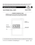
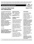
12 INCH MITER SAW WITH LASER
CALIFORNIA PROPOSITION 65
SPECIFICATIONS
WARNING: You can create dust
when you cut, sand, drill or grind
materials such as wood, paint,
metal, concrete, cement, or other
masonry. This dust often
contains chemicals known to
cause cancer, birth defects, or
other reproductive harm. Wear
protective gear.
Motor: 120V/15A
Speed: 4100 RPM
Blade Diameter: 12 inch
Table Tilting Range: L-45° R-45°
Saw Body Tilting Range:0-45°
WARNING: This product or its
power cord may contain
chemicals, including lead,
known to the State of California
to cause cancer and birth
defects or other reproductive
harm. Wash hands after
handling.
CAUTION:
FOR YOUR OWN SAFETY READ
INSTRUCTION MANUAL
COMPLETELY AND CAREFULLY
BEFORE OPERATING THIS
MITER SAW.
WARNING!
Read and understand all
instructions.
Failure to follow all
instructions listed below may result
in electrical shock, fire and/or
serious personal injury.
SAVE THESE
INSTRUCTIONS
SAFETY INFORMATION
Always wear proper safety
protection; safety goggles
should be worn at all times.
Dust mask, non-skid safety
shoes, hardhat, or hearing
protection should also be worn
at appropriate times.
Model: 8637
Use the special flanges
provided for this tool only.
Secure the saw to a
workbench or table before
use to prevent unexpected
saw movement.
Make sure that the work area
is clear of debris before
starting.
Before cutting, make sure
that the work piece is free of
nails, screws, or other foreign
objects.
Make sure that the armature
shaft is free from lock by the
shaft-locking arm before you
turn it on.
Do not operate in the presence
of explosive materials, such as
flammable liquids, gases, or
dust.
Make sure that the saw blade
will not touch the rotary table
when the saw blade is in its
lowest position.
Maintain tools with care. Keep
blades sharp and clean. If the
blade is broken or deformed,
replace immediately.
Never operate this tool with
one hand. Secure work piece
with the vise, never secure
the work piece by hand.
Be careful not to damage the
output spindle, flanges
(especially the fitting surfaces)
and the bolt. Check whether the
saw blade is in good condition.
Hold the handle firmly.
For Customer Service, please call 1-800-358-5004 or email [email protected]
Never let your hands get
close to the cutting line; do
not touch the saw blade.
8808637
07/10
Give the saw a test run before
cutting. If the tool vibrates
excessively or makes unusual
noises, stop operating the saw
immediately and correct the
problem.
Before lowering the blade to the
work piece, make sure it has
reached maximum speed.
maintenance or changing
the blade.
To remove the blade, loosen the
bolt in the central cover by
turning it counterclockwise, using
the socket wrench provided.
Then, raise the central cover and
move it down from the original
position.
If anything appears to be wrong,
turn the tool OFF and stop
working immediately.
Before performing any
maintenance or adjustments,
make sure that the power is
OFF and the saw blade has
stopped completely.
Always remain alert, watch what
you are doing, and use common
sense when operating a power
tool. Do not use when tired, or
under the influence of drugs,
alcohol, or medication.
Use only recommended
accessories specific for the
power tool.
Do not abuse the cord. Never
use the cord to carry the tool or
pull the plug from an outlet.
Keep the cord away from heat,
oil, sharp edges, or moving
parts. Replace damaged cords
immediately.
When removing the saw blade,
first raise the handle to the
highest position, press down the
shaft-locking arm to lock the saw
blade in place, and loosen the
hex bolt by turning clockwise
using the socket wrench. Then,
remove the hex bolt, outer
flange, and saw blade.
KEEP THESE
INSTRUCTIONS FOR
FURTHER REFERENCE
CHANGING THE SAW
BLADE
Unplug the saw before
performing any
[email protected]
Install the new saw blade. Check
that the teeth point in the
direction of the arrow (see the
protective cover).
2
Install the outer flange and the hex
bolt, then press down the shaftlocking arm, and tighten the hex
bolt firmly by turning it
counterclockwise using the socket
wrench. Then secure the central
cover back in place by adjusting
the hex bolt. When removing the
saw blade, lift up the movable hood
and central cover, loosen the hex
bolt with the socket wrench,
remove the hex bolt, outer flange,
and saw blade.
MOVEABLE HOOD
When sawing, the movable
hood will be lifted up by the
work piece. The movable hood
will automatically be reset to its
original position when the
handle is raised after you finish
cutting. Never abandon or
remove the movable hood.
OPERATING THE
SWITCH
SAWDUST
COLLECTOR
You can operate this machine
more conveniently with the
sawdust collector. Connect the
adapter of the collector to the
nozzle of the protective cover,
and then fix the collector inlet to
the adapter of the collector.
When the sawdust collector is
half full, take the collector off
from the protective cover, open
the collector door at the bottom,
and clean out the sawdust.
To prevent accidental starting,
this tool is equipped with a
protective switch. To start the
tool, you should first press the
protective switch and press down
the trigger switch. When you
release the trigger switch, the
tool is switched off.
OPERATION
1. Press Cut (cut small work
piece)
The work piece size within the
scope: 4in. (H) x 13in. (W) can
be cut in the following way.
Push the carriage to the end
towards the cross bar, tighten the
knob to fix the carriage. Use the
vise to secure the work piece.
Switch the machine on, wait until
the saw blade reaches its
maximum speed, and then press
the handle downwards slowly. After
you have finished cutting, turn the
switch off and wait until the saw
blade comes to a complete stop
before raising the handle
completely.
2. Slip cut (cut wide work pieces)
The work piece size within the
scope: 4in. (H) x 8 1/2in. (W) can
be cut in the following way.
Release the knob in order to slip
the carriage freely, completely pull
the carriage towards the operator.
Switch the machine on and wait
until the saw blade reaches its
maximum speed, then press the
handle and push it to the cross bar
in order to cut the work piece. Once
you have finished cutting, turn the
switch off and wait until the saw
blade comes to a full stop, then
raise the handle completely.
SET A BEVELED JOINT
ANGLE
Loosen the hand shank by turning
[email protected]
3
it counterclockwise. Press down
the spring pin so that the rotary
table is free to turn. When the
desired angle on the base scale
matches up with the arrow
marked on the rotary table, turn
the hand shank clockwise to
tighten it.
SECURE THE WORK
PIECE
SET A BEVELING
ANGLE
Only when the auxiliary stopper
is fixed on the left side (as
shown) can the saw blade be
beveled to a 45 degree angle.
To adjust a beveling angle,
loosen the fixed handle, then
incline the saw blade to the left
until the indicator reaches the
desired angle on the miter
square. Tighten the fixed handle
firmly.
The vertical vise can be installed
in hole of guide bar or the work
piece supporter component
(selective purchasing). Install the
vise rod in the hole of the guide
bar or work piece supporter
component, then tighten the bolt.
You should adjust the position of
the vise arm according to the
thickness and shape of the work
piece and tighten the vise arm
with the bolt. Lean the work
piece against the guide bar and
the rotary table and place the
work piece on the desired cutting
position then tighten the clamp
bolt to secure the work piece.
maximum cutting capacity using an
8 inch saw blade. When the
diameter of the saw blade becomes
smaller because of grinding, please
adjust the machine as follows:
Lower the carriage to the cross bar,
completely put down the handle to
the lowest position. Make sure the
blade is properly aligned. Unplug
the cord and use your hand to spin
the blade. The blade should spin
smoothly without making contact
with any other part of the saw. If
there is contact, realign the blade
before using the saw. With the
socket wrench, turn the adjustable
bolt to make the edge of the saw
blade fit into place, ensuring that it
falls slightly below the rotary table.
Make sure that the saw is
unplugged, then press the handle
to the lowest position to ensure that
the blade does not touch the table
below. Then, if necessary, adjust
the blade.
Note: Before installing the new saw
blade, make sure it does not
contact any part of the table below.
MAXIMUM CUTTING CAPACITY
KEEP THE MAXIMUM
CUTTING CAPACITY
Before any adjusting, unplug the
saw from the power source. This
machine has been adjusted by
the manufacturer to keep the
[email protected]
4
0
0
4 x 12 1/2 inch
0
45°
4 x 10 inch
45°
45°
2 x 8 1/2 inch
45°
0
2 x 12 1/2 inch
REPLACING THE
CARBON BRUSHES
Check and remove the carbon
brushes regularly. When the
brushes wear down to the limit
mark, they should be replaced
right away. Keep the carbon
brushes clean and free to slip in
the holders. Both carbon brushes
should be replaced at the same
time.
Use a screwdriver to remove the
brush holder caps. Take out the
worn carbon brushes, insert the
new ones and secure the brush
holder caps.
[email protected]
5
North American Tool Industries (NATI) makes every effort to ensure that this product meets high
quality and durability standards. NATI warrants to the original retail consumer a 1-year limited
warranty from the date the product was purchased at retail and each product is free from defects in
materials. Warranty does not apply to defects due directly or indirectly to misuse, abuse, negligence or
accidents, repairs or alterations, or a lack of maintenance. NATI shall in no event be liable for death,
injuries to persons or property, or for incidental, special or consequential damages arising from the
use of our products. To receive service under warranty, the original manufacturer part must be
returned for examination by an authorized service center. Shipping and handling charges may apply. If
a defect is found, NATI will either repair or replace the product at its discretion.
[email protected]
6
12 Inch Miter Saw with Laser
08637
For Customer Service, please call 1-800-358-5004 or email [email protected]
7
8808637
07/10
No.
Description
QTY
No.
Description
QTY
No.
Description
QTY
1
Indexing Handle
1
31
Washer D8
5
61
Hex Bolt M5x50
4
2
Indexing Spanner
1
32
Hex Bolt M10x85
1
62
Hex Bolt M10x15
1
3
Indexing Pin
1
33
Spring Washer D8
4
63
Flat Washer D5
18
4
Pin D3x20
1
34
Hex Bolt M8x25
4
64
Motor Enclosure
1
5
Indexing Spring
1
35
Plastic Stop Fence
1
65
6
6
Indexing Cover Plate
1
36
Braking Ring
1
Cross Head Screw
M4x25
Sunk Head Screw
M5x12
Hex Bolt M6
5
Sensor
2
6
37
66
7
38
Lock Screw M6x25
2
67
Cord Plate
1
8
Hex Bolt M8x55
1
39
Rocker
2
68
Carbon Brush
2
9
Nylon Lock Nut M8
1
40
Lever of Vise
1
69
Screw ST4.2x13C
2
10
Lock Screw M6x10
2
41
Spring Washer D4
5
70
Holder of Carbon Brush
2
11
Worktable
1
42
Press Plate
1
71
Switch Actuating Spanner
1
12
Big Rubber Ring
2
43
Vise Jaw
1
72
Cover of Holder of Brush
2
13
Slide Bar
1
44
Heart
2
73
Spring
1
14
Long Slide Bar
2
45
Indexing Handle
1
74
Switch Handle
1
15
Clip Spring D40
2
46
Hex Nut M10
2
75
Stop Bolt
1
16
Dustproof Cover
4
Bracket of Slide Bar
Support
76
Switch
1
47
1
77
Screw ST3.5x9C
1
17
Felt Ring
4
18
Shelf
2
48
Ring
2
78
Capacitance
1
19
Cross Screw M4x8
3
49
Small Rubber Ring
2
79
End Cover
1
20
Washer
6
50
Slide Bar Support
1
80
Power Supply Cord
1
21
Rocker Graduation
1
51
Flat Washer M10
3
81
Cord Guard
1
22
Bracket
1
52
Spring Washer M10
2
82
Safety Assembly Button
1
23
Rocker Needle
1
53
Spring Rivet D2.5x18
1
83
Safety Assembly
1
24
Cross Screw M4x10
5
54
Lock Nut
1
84
Screw M4x6
1
25
Bolt
7
55
Spring
1
85
Spring Washer
1
26
Rubber Bracket
5
56
Rivet
1
86
Spring
1
27
Base
1
57
Hex Bolt M10x50
2
87
Shaft of Safety Assembly
1
28
Cushion Plate
3
58
Nylon Lock Bolt
1
88
Clip D6
1
29
Fence
1
59
Lever of Bolt M8x35
1
89
Spring of the Rocker
1
30
Linear Bearing
3
60
Lock Handle
1
90
Dust Bag Pipe
1
[email protected]
8
No.
Description
QTY
No.
Description
QTY
No.
Description
QTY
91
Hex Bolt M6x20
1
116
Bearing ø17xø40x12
1
141
No. 7 Battery
2
92
Lock Screw M5x20
1
117
Cover of Bearing
1
142
Laser Switch
1
93
Hex Bolt M6x40
1
118
Screw M5x16
2
143
Screw ST4.2x10
2
94
Screw M6x25
1
119
Shelf
1
144
Touching Part 1
1
95
Safety Guard
1
120
Inner Flange
1
145
Battery
1
96
Fixed Plate of Movable
Safety Guard
1
121
Saw Blade
1
146
Touching Part 2
1
122
Outer Flange
1
147
Touching Part 3
1
97
Screw M6
1
123
Screw of Shaft
1
148
Bearing ø10xø30x9
1
98
Gear
1
124
Shaft Washer
1
149
Rotor Assembly
1
99
Hex Bolt M5x10
3
125
C-Type Flat Key
1
150
Stator Assembly
1
100
Screw
2
126
Bevel Gear
1
151
Screw M5x70
2
101
Cover of Gear
1
127
Spring ø17
1
152
Bearing ø15xø35x11
1
102
Screw M4x5
3
128
Screw M5x12
7
153
Oil Bearing
1
103
Gear
1
129
Kerf Board
1
154
Zine Holder of Laser
1
104
Spring
1
130
Needle
1
155
Bushing of Laser Head
1
105
Rivet
1
131
Push Handle
1
156
Laser Head
1
106
Movable Safety Guard
1
132
Spring
1
157
Cover of Laser Head
1
107
Washer
1
133
Lock Nut Assembly
1
158
Screw M4x16
6
108
Spring Washer M6
1
134
Stopper Plate
1
159
Cap NutM10
1
109
Cap Nut M6
1
135
Wave-Type Washer
1
160
Positioning Plate
1
110
Wind Resisting
1
136
Screw M4
1
161
Plastic Plate
1
111
Fan
1
137
Column Pipe
1
162
Slide Slot of Gear
1
112
Gear Holder
1
138
Slide Bar Ring
1
163
Spring Washer D5
7
113
Rotor Clip Spanner
1
139
Screw
1
164
Hex Screw M4
1
114
Spring
1
140
Cover of Battery Box
1
115
Rotor Clip
1
9