1
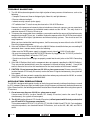
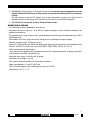
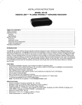
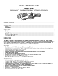
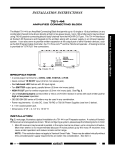
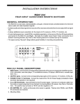
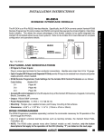
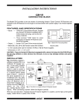
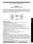
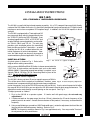
291-80 CFL FRIENDLY INFRARED RECEIVER The 291-80 is a small shelf-top infrared repeater assembly. It is a CFL (compact fluorescent light) friendly version of the 291 Hidden Link series. It is specifically designed to have great immunity to CFL type infrared interference and to have exceptional IR reception range. In addition, the 291-80 will operate in direct sunlight! 291-80 IR Receiver Hand Held Remote 781RG Satellite Receiver Power Supply (Not Included) VCR To 120 V AC (Unswitched) 7-Foot 3Conductor Cable with Quick Connect Mini Plug V G S IR RCVR CB12 Connecting Block (Included) INSTALLATION A typical system is shown in Fig. 1. Refer to this diagram when making connections: Equipment Mounted Behind Closed Doors Model 286M Dual Blink IR™ Mouse Emitter (Not Included) PWR OUT The 291-80 is equipped with a 7-foot cable and 3.5 mm stereo mini plug, which is plugged directly into the "IR RCVR" jack on the CB12 (included). It can also be plugged into the "AUX" or "IR RCVR" jack on other Xantech connecting blocks, such as models 789-44, CB-60 and 791-44. The mini plug provides quick installation where the connecting block is within reach of the 7-foot cable — as when installing the 291-80 in a cabinet where the controlled equipment is behind closed doors. However, the cable length can be easily increased to accommodate any desired application. See Fig. 4. Fig. 1 3-Conductor Cable to IR Receivers in Other Rooms. (Optional - See Fig. 3) The 291-80 in a Typical IR Repeater In this system a 286M Dual Blink-IR Emitter is shown connected to the "OUT" jack. A single emitter could also be used, such as the model 282M or 283M. If expansion beyond two emitters is required, use a Xantech 789-44, CB-60 or 791-44 Connecting Block in place of the CB12. Do not use the CB12 in this case. 42 kHz 48 kHz 38 kHz Full CCW 56 kHz Full CW 32 kHz Adjusting the IR Carrier Frequency 291-80 Adjustment The 291-80 is factory set to an IR carrier repeat frequency of 38 kHz. This will be correct for the majority of installations. However, some Fig. 2 IR Carrier Frequency Adjustment manufacturer's components that you wish to control may use different carrier frequencies (such as the RCA DSS receivers that use 56 kHz). If such carrier frequencies fall within the range of 32 kHz to 56 kHz, you can adjust the 291-80 to match them for best range performance. The adjustment can be made through a small opening on the rear panel. See Fig. 2. To adjust, proceed as follows: 1. First, try the 291-80 in a repeater system. If it works well with good range, do not make any adjustments! 2. If it does not work or has poor range (less than 15 feet), determine the IR carrier frequency of the product you wish to control. Contact the manufacturer of the product, if necessary, to determine this frequency. 3. Using a small blade type screwdriver (3/32" blade width max.), rotate the adjustment shaft until the slot lines up with the desired frequency marking. Refer to Fig. 2. NOTE: The frequency markings shown in Fig. 2 are approximate only. You may need to "fine tune" the adjustment for best performance. 1 IR Receivers & Modems INSTALLATION INSTRUCTIONS 4. If you have products in the same IR system that have different IR carrier frequencies, you will have to adjust the 291-80 to a midway position. For example, some products may operate at 38 kHz and others at 56 kHz. In this case, set the adjustment to approximately 47 kHz, a midway position just to the right of the 48 kHz marking in Fig. 2. NOTE: Some products are more tolerant of compromised frequency settings than others. You may have to "fine tune" the adjustment to "favor" the least tolerant component for the best performance of all units in the system. Connecting IR Receivers From Other Rooms The CB12 Connecting Block, supplied with the 291-80, has a three terminal input strip for connection of external infrared receivers should you wish to control your equipment from other rooms. • The terminals are marked V G S. (V= +12V, G=Ground and S=IR Signal). • Make connections as shown in Fig. 3. Run a 3-conductor cable from each remote room to the VGS terminals on the CB12. (Use 24 gauge solid or stranded wire up to 200', 22 gauge up to 600', 20 gauge up to 2000' and 18 gauge up to 5000' (unshielded OK). • When you use a 291-10 or a 291-80 IR Receiver in a remote room, do not plug in a power supply or use the "OUT" jack on that particular CB12, as shown in 291-80 IR Receiver ROOM 3 of Fig. 3. Hand Held Remote • You may use more IR receivers, in additional rooms, connected in the same manner. When connecting more than ten 291-80's, use the higher current power supply, Model 782-00. ROOM 3 ROOM 2 291-10 IR Receiver 780-10 781RG Power Supply (See Text) X J-BOX RECEIVER 780-10 +12V To 120 V AC (Unswitched) XANTECH CORPORATION SYLMAR, CA 91342 +12V OUT X CB12 Connecting Block IR RCVR VCR J-Box IR Receiver 7-Foot 3Conductor Cable with Quick Connect Mini Plug PWR OUT Satellite Receiver OUTPUT GND GND V G S 291-80 Cable Connections Model 286M PWR OUT Dual Blink IR™ V G S Mouse Emitter The 291-80 may also be used (Not Included) IR where the 7-foot cable is not RCVR long enough. Simply cut off Equipment CB12 Connecting Block Mounted Behind the mini plug, strip the leads Closed Doors ROOM 1 and splice them to a 3-conFig. 3 Connecting IR Receivers From Other Rooms ductor extension cable using a terminal block or other means. Then connect the extension cable to the 3-terminal block on the CB12. 3-Conductor Room-to-Room Cable (unshielded OK) Refer to Fig. 4 and the table below to identify the leads for correct connections. Table Lead Identifications 3-Conductor Extension Cable RED V G S +12V GND WHITE SIG PWR OUT CB12 IR RCVR 291-80 PLUG CABLE LEADS CIRCUIT ITEM RING BLACK GROUND TIP WHITE SIGNAL SLEEVE RED + 12 V BLACK 7 Foot 3-Conductor Cable with Mini Plug Removed Ring 3-Terminal Block (not included) Tip Stereo Mini Plug Sleeve Insulators Fig. 4 Direct Wire Connections 2 291-80 • Compact Fluorescent, Neon or Halogen lights, Neon Art, and light dimmers. • Direct or reflected sunlight. • Infrared security sensors (active types). • RF radiation from TV sets that may be close to the 291-80 IR Receiver. However, in the presence of extremely intense interference from such sources, you may experience a reduction in range between the handheld remote control and the 291-80. This may result in a reduction from over 70 feet to 15 feet or so. 2. To improve the range under these conditions, you need to confirm the source of the interference by temporarily turning off TV sets, etc. In addition, reduce the exposure of the 291-80 IR Receiver to direct sunlight and turn off all lights, light dimmers and Infrared security systems. Then check to see if the range improves. When you have isolated the interfering source, it will be necessary to move either it or the 291-80 IR Receiver to improve operation. 3. If the red Talk-Back LED on the 291-80 or the 286-00 Emitters do not blink when you are sending IR commands from a remote control, check the following: • Make sure the 781RG power supply is plugged securely into a live 120V AC wall outlet. • Be sure the stereo mini plug of the 291-80 IR Receiver is plugged into the "IR RCVR" jack on the CB12 Connecting Block, not into the "OUT" jack. • Check to see that all the mini plugs are properly seated into the mini jacks on the CB12 Connecting Block. 4. If the 286-00 Emitters blink, but the component does not respond, reposition the 286-00 Emitter(s). They may not be located directly over the component’s infrared receiving "window". Consult the owner's manual of the unit or the manufacturer for the exact location of the infrared "window". 5. CAUTION: Do not use more than one 291-80 in a given room or area! If two or more 291-80's, (or other Xantech CFL friendly IR receiver) receive the same IR signal simultaneously, the system will not respond. 6. If the system still does not work, contact the dealer from whom you purchased the 291-80, or contact XANTECH Technical Support at 800-843-5465. APPLICATION PRECAUTIONS The 291-80 is designed with special circuitry so that is has great immunity to infrared interference caused by CFL (compact fluorescent light) and other types of high frequency electronically ballasted fluorescent lights. Because of this, the following precautions must be taken into consideration when using these special IR receivers: 1. Do not use more than one 291-80 in a given room or area! If two or more 291-80's, (or other Xantech CFL friendly IR receiver) receive the same IR signal simultaneously, the system will not respond. 2. The 291-80 (or other Xantech CFL friendly IR receivers) will not operate with Xantech products that use 679 and RC16 Programmer commands! This includes models 670-00, 671-00, 676-00, 677-00, 680-00, 686-00 and RT16-00. For installations using these products, use standard Xantech IR Receivers, such as the 291, 480, 490, and 780-10 series. 291-80 3 IR Receivers & Modems TROUBLE SHOOTING 1. The 291-80 has been designed to have high rejection of many sources of interference, such as the following: 3. The 291-80 (or other Xantech CFL friendly IR receivers) do not have improved operation over the standard Xantech IR Receivers in the presence of magnetically ballasted (60 Hz) fluorescent lighting. You may choose to use the CFL friendly units in most applications anyway, since they will have superior rejection to other types of IR interference that may exist in the same installation. 4. The 291-80 will not operate in 2-wire Phantom Power mode. SPECIFICATIONS • IR modulation frequency bandwidth: 30 to 60 kHz. • Adjustable IR carrier frequency: 32 to 56 kHz (allows matching to actual controlled component for optimum performance). • IR reception range: Up to 70 feet on axis (range depends on device being controlled and levels of IR or EM interference). • Red talkback LED tests system for correct wiring as well as indicating infrared reception. • Nominal reception angle: 45 degrees off axis. • Attached 7' cable and 3.5 mm stereo mini plug permits direct plug-in to Xantech Connecting Blocks that have an "IR RCVR" or "AUX" jack, such as the CB12, CB20, CB60, 789-40, 791-40, etc. • Cable requirements for long lengths: Three-conductor/24 gauge solid or stranded wire up to 200', 22 gauge up to 600', 20 gauge up to 2000' and 18 gauge up to 5000' (unshielded OK). • Maximum cable length: One mile with 18 gauge. • Maximum current output: 100 mA. • Use Xantech Connecting Blocks for connection to emitters. • Power Consumption: 12 volts DC @ 20 mA. 781C-00 Power Supply (not included) powers up to six 291-80's. • Dimensions: 3-1/4" x 1" x 2". 2-24-00 4 291-80