1
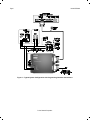
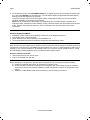
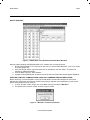
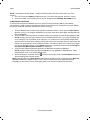
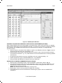
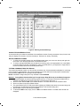
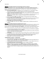
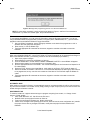
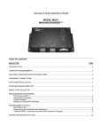
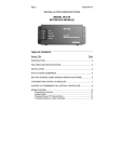
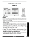
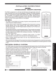
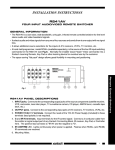
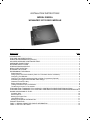
INSTALLATION INSTRUCTIONS MODEL IRS232A ‘ADVANCED’ IR TO RS232 MODULE TABLE OF CONTENTS Section Title Page INTRODUCTION ................................................................................................................................................. 3 FEATURES AND SPECIFICATION ..................................................................................................................... 3 COMPUTER REQUIREMENTS (minimum).......................................................................................................... 3 INCLUDED HARDWARE & SOFTWARE ITEMS ................................................................................................. 3 HARDWARE CONNECTIONS............................................................................................................................. 3 SOFTWARE INSTALLATION .............................................................................................................................. 3 STARTING DRAGON DROP-IR .......................................................................................................................... 4 SERIAL PORT SELECTION ................................................................................................................................ 4 PLANNING THE SYSTEM................................................................................................................................... 4 PROGRAMMING THE IRS232A .......................................................................................................................... 5 Select Base Unit............................................................................................................................................... 5 Verifying Com Port Communication (“Who Am I” Firmware Version Verification)............................................... 5 Configuring The IRS232A................................................................................................................................. 6 Changing The Code Group Manually With An RC68+ Programmer (Optional) .................................................. 7 Associating IR Trigger Commands With ASCII Strings...................................................................................... 7 Character Conversion Utility ............................................................................................................................. 8 Editing Command Strings................................................................................................................................. 8 Testing Commands From The IRS232A ........................................................................................................... 8 Transferring A Project To The Irs232a .............................................................................................................. 9 TEACHING RC68+ COMMANDS TO A HAND-HELD CONTROLLER OR KEYPAD FROM AN RC68+ ............. 10 TEACHING RC68+ COMMANDS TO A HAND-HELD CONTROLLER OR KEYPAD FROM DRAGON DROP-IR 10 SAVING AND BACKING-UP FILES ................................................................................................................... 10 Automatic Save.............................................................................................................................................. 10 Save Project As.............................................................................................................................................. 10 Backing-Up Project Files ................................................................................................................................ 11 Using Backup Files......................................................................................................................................... 11 Backing-Up SmartPad and Palette Files ......................................................................................................... 11 TROUBLE SHOOTING...................................................................................................................................... 11 TABLE 1 - IRS232A CONNECTOR PINOUT INFORMATION ............................................................................ 12 TABLE 2 - DEFAULT SETTINGS....................................................................................................................... 12 Page 2 Model IRS232A Figure 1 – Typical System Configuration with Programming Hardware Connections © 2002 Xantech Corporation Model IRS232A Page 3 INTRODUCTION The IRS232A, IR to RS232 Module, provides IR control of advanced components such as projectors and lighting systems that would normally be controlled via RS232 with exotic controllers or automated systems. The IRS232A has advanced features allowing it to be compatible with a wide variety of RS232 controlled devices. FEATURES AND SPECIFICATIONS Converts Xantech RC68+ IR codes to RS232 ASCII commands Program up to 36 different RS232 command strings each with up to 100 characters Support of multiple Baud Rates including 300bps, 1200, 2400, 4800, 9600, 19.2k, 38.4k, and 115.2kbps. User configurable Stop Bit, Data Bit, and Parity parameters Power Indicator LED (Lights solid RED indicating unit is powered) RS232 OUTPUT LED (Blinks GREEN when RS232 commands are triggered and when Dragon Drop-IR download is in progress) Accepts Hex Commands and printable/non-printable ASCII characters Decimal/HEX/Binary character Conversion Utility (DRAG460 v1.04 and higher) Support of “WHO AM I” version recognition using DRAG460 v1.04 and higher Backwards compatible to DRAG460 v1.03 Dragon Drop-IR Programming Software and PC DB-9 Program Cable included Mounting-flanges, permits easy mounting to flat surfaces Power requirements: 12VDC ±1.5V @30mA Dimensions: 4.25” W x 1.20” D x 4.25” H (108mm x 31mm x 83mm) COMPUTER REQUIREMENTS (MINIMUM) • 486 66-MHz IBM® Compatible Computer (Pentium versions preferred) • Windows 95/98/NT/2000/ME/XP • 5 MB Hard Drive space (you will need more as your IR palette libraries expand) • 16 MB RAM (32 MB preferred) Available PC COM Port • Mouse INCLUDED HARDWARE & SOFTWARE ITEMS To use the DRAG460 Software, you will need the following items included with Dragon Drop-IR™. 1. CD ROM Disc. Contains the Dragon Drop-IR software, plus IR Code and Product files. 2. One DB9 Male-to-Female Programming Cable. HARDWARE CONNECTIONS Refer to Figure 1: 1. Using 2-conductor cable (22AWG up to 600’, 20AWG up to 2000’ and 18AWG up to 5000’), connect PWR GND, and +12VDC connections from the IRS232A module to the appropriate terminals on the connecting block. 2. Using a Mono Mini-Plug to Stripped Ends 2-Conductor cable (Xantech PN#06015900, not included), plug the Mini-Plug end into an available Emitter out on the Connecting Block and wire the ‘Stripped End' in IR IN (White Stripe) and IR GND on the IRS232A. 3. Connect the COM PORT of the IRS232A to an available COM PORT of the PC running DRAG460 4. Connect the RS232 Port of the IRS232A to the product to be controlled to test commands SOFTWARE INSTALLATION The installation software for the DD460 system is included in the supplied CD ROM. Install the Dragon Drop-IR™ Software onto your hard drive as follows: Windows 95/98/NT/2000/ME/XP 1. Insert the Dragon Drop-IR CD into your CD-ROM drive. If your drive has been set for auto run, a ‘Xantech Welcome’ menu will appear. If not, access your CD ROM drive with Windows Explorer and double click on the "autorun.exe" file. © 2002 Xantech Corporation Page 4 Model IRS232A 2. On the Welcome menu, click Install DD460 Software. (If upgrading from a previous version of Dragon DropIR 460, select REPAIR from the install menu. This will add and replace all appropriate files while keeping existing projects and palette files un-touched.) Follow the on-screen instructions as the program installs. It takes approximately one to three minutes to complete, depending on the speed of your machine. NOTE: For the convenience of the installer, the Dragon Drop-IR™ CD ROM contains a complete set of Application Notes, the Xantech Product Catalog, Factory Learned IR Codes, web site browsers and important notes. Read the Very Important Notes first, click on the desired menu item and follow the on-screen instructions. STARTING DRAGON DROP-IR Windows 95/98/NT/2000/ME/XP 1. Installation creates a shortcut on the desktop. Double click on the Drag460 Shortcut or: 2. From START menu, choose Programs. 3. Select XANTECH from the list and click on the DRAG460 Icon. 4. The program loads and opens to the Xantech Dragon Drop-IR programming screen. SERIAL PORT SELECTION When first launched, the Dragon Drop-IR software scans the serial ports and will display the available ports under "Preferences" in the File menu. Unavailable ports will be grayed out. Com Port 1 would normally be used, but if it is already in use, it will be necessary to use a different one. If your computer only has a USB connection, a USB to Serial Adapter (including software) can be purchased at most computer stores. Select the Com Port as follows: 1. Click Preferences (F2) from the File menu. 2. Click on an available port, then OK. PLANNING THE SYSTEM Before attempting any programming, plan the system configuration first. This should include the following: a) Determine the brands and types of all components you expect to use. b) Acquire the HEX or ASCII text commands for the component that will be interfacing with the IRS232A. These can be found in the product’s installation manual, manufacturer’s web site or manufacturer’s tech support. c) Determine if a Null-Modem cable will be necessary for communicating to the device. © 2002 Xantech Corporation Model IRS232A Page 5 PROGRAMMING THE IRS232A SELECT BASE UNIT Figure 2 – IRS232 Base Unit and RS232 Command Editor Windows With the system operating and DRAGON DROP-IR™ software open, proceed as follows: 1. Choose “NEW PROJECT” (CTL+N) from the File menu or choose “OPEN PROJECT” (CTL+O) to modify an existing project file). 2. In the New Project window, type a file name such as “joneshome” and click “SAVE”. The proper file extension is added automatically. 3. From the Base Unit menu, select “IRS232”. 4. A graphic window (IRS232) with 36 buttons and an RS-232 Command Editor window appears. Figure 2. VERIFYING COM PORT COMMUNICATION (“WHO AM I” FIRMWARE VERSION VERIFICATION) Before continuing, it is recommended to verify proper COM PORT communication between the PC and the IRS232A. By checking the unit’s firmware version and verifying a response from the IRS232A, you will confirm proper communication and may continue. 1. To check firmware version, simply click on the Base Unit menu and select “Who Am I”. 2. This should return a version number as shown in figure 3 below. Figure 3 - “Who Am I” Firmware Verification © 2002 Xantech Corporation Page 6 Model IRS232A NOTE: If a message is returned stating: “Unable to Determine Base Unit” this could be due to one of the following: 1. The unit is the original IRS232 (non-Advanced unit). This does not support the “Who Am I” feature. 2. There is a problem communicating with the device. Please see the TROUBLE SHOOTING section CONFIGURING THE IRS232A You will need to configure the IRS232A unit for the proper IR code group setting and for proper RS232 communication. Please consult the manufactures manual for the product to be controlled for the proper RS232 settings (i.e. Baud Rate, Stop Bits, and Data bits.) before continuing. 1. Click the OPTions button located in the top left of the IRS232 window. This will open the Base Options Window. Here you can configure the IRS232 unit for proper Code Group, Baud Rate, Stop Bits and Data Bits. See Figure 4. 2. Confirm proper Code Group setting. The default code group for RC68+ IR codes for the IRS232A is “38”. NOTE: Changing the code group will allow control of multiple IRS232 units; e.g. having one IRS232 unit set to code group “38” and another set to code group “10” will allow both units to operate independently within the same IR Zone. When changing code groups, be sure the new setting does not interfere with the default code group setting of another Xantech product in use within the same zone. Code group changes can also be changed ‘manually’ using an RC68+ programmer. Please see the sectioned titled Changing the Code Group Manually With an RC68+ for instructions. 3. Confirm proper RS232 transmission parameters for Baud Rate, Stop Bits and Data Bits. NOTE: Changes to Baud Rate, Stop Bits and Data Bits are only applicable to IRS232A units. These parameters are ‘fixed’ on the original IRS232 units. 4. After all settings are confirmed, click the located in the top right corner of the Base Options window to save the settings and close the window. NOTE: Changes made in the Base Options window will be transferred to the unit during the next Base Unit Transfer (transferring of Dragon Project to unit). If the unit transferred to is the original IRS232 (non IRS232A), you will need to remove and re-apply power to the unit before changes will take affect. © 2002 Xantech Corporation Model IRS232A Page 7 Figure 4 – IRS232 Options Window CHANGING THE CODE GROUP MANUALLY WITH AN RC68+ PROGRAMMER (OPTIONAL) When multiple IRS232A units will be used together in the same IR Zone, each unit will need to be on a separate Code Group to enable each unit to be addressed individually. The code group can either be changed via software during a BASE UNIT TRANSFER as mentioned in the previous section or manually. To change manually, proceed as follows: 1. With an IR sensor connected to IR IN, GND and +12VDC on the IRS232A, as shown in Figure 1, set the Code Group switches on the rear of the RC68+ to “FF”. 2. Press the button on the RC68+ of the Code Group to be used for control. (Use the screened characters on the buttons for reference. e.g. “10”.) Hold the button for a few seconds and look for confirming talkback on IR receiver. 3. Change Code Group switch on the rear of the RC68+ to the new code group setting, “10”. 4. Create and transfer a project in DRAGON DROP-IR™ for the IRS232A. 5. Using the RC68+ test IRS232A for response to the new Code Group. ASSOCIATING IR TRIGGER COMMANDS WITH ASCII STRINGS 1. Select a button in the IRS232 window. It will be highlighted in a blue outline. (Refer to Fig. 5) 2. In the RS-232 Command Editor window, place the cursor in the box under the column labeled 01. Type the ASCII text command to be sent. If only the HEX code is known, simply place the cursor in the row labeled HEX and enter the command. NOTE: The maximum number of characters in a string is 100. 3. Repeat steps 1 and 2 for as many strings as needed up to 36 strings 4. It is recommended to test the commands before transferring the project to the unit via BASE UNIT TRANSFER. © 2002 Xantech Corporation Page 8 Model IRS232A Figure 5: Entering Command Strings CHARACTER CONVERSION UTILITY A conversion utility is included in the RS232 Command Editor window. Entering commands of any format in this utility will display the character in all other formats (i.e. Decimal, Hex, Binary, and ASCII). EDITING COMMAND STRINGS 1. To remove a command entirely from the IRS232 window, place your cursor over the key and right-click the mouse. From the drop-down menu choose DELETE KEY. 2. To remove a single ASCII/HEX text command from a string, click on the appropriate ‘box’ in the RS232 Command Editor so the box is highlighted in yellow. Press DELETE on your keyboard or ‘Right-Click on the box and select DELETE from the drop down menu TESTING COMMANDS FROM THE IRS232A There are three methods in which you can test the commands. Any of these methods is adequate for confirming proper operation of the IRS232A. Two of these methods can be done before the actual project is transferred to the unit utilizing TEST mode in the Dragon Drop-IR software. NOTE: Test Mode in Dragon Drop-IR is only available in Model IRS232A Method 1: Testing RS232 Command Strings Through Dragon Drop-IR Directly to the RS232 Component 1. Leave the IRS232A connected as during programming (i.e. PC Comport connected to COM PORT on IRS232A, and RS232 Out connected to the unit to be controlled). See Figure 1. 2. Click the button labeled TEST in the IRS232 Window. The button should now be outlined in RED. 3. Click on a button to test in the IRS232 window. 4. The green RS232 OUTPUT LED should flash indicating the IRS232A has issued a command string and the unit being controlled should respond appropriately to the command being sent. 5. Repeat Steps 4 & 5 for each string to be tested. 6. To terminate TEST mode, simply click on TEST in the IRS232 window. The RED outline should now disappear. © 2002 Xantech Corporation Model IRS232A Page 9 Method 2: Testing RS232 Commands Through Dragon Drop-IR to PC Screen NOTE: This requires either 2 PC’s or a PC with two COM Ports. A communication program such as Hyperterminal is also required. This is an ‘advanced’ testing method and can be used as a trouble shooting tool if the Method 1 test did not control the unit appropriately. This will allow you to visually confirm the IRS232A is outputting the correct command string. 1. Connect the IRS232A as shown in Figure 1 but connect the RS232 OUT via a “Null-Modem” cable to either another PC’s COM Port or to another COM Port on the PC running Dragon Drop-IR. 2. On the PC connected to the RS232 OUT of the IRS232A, open the RS232 Communication software and configure for the proper communication settings. NOTE: If you are using the same PC, you should now have 2 programs running; Dragon Drop-IR™ and the RS232 Communication software. Arrange the two programs so both windows are visible simultaneously. 3. Click the button labeled TEST in the IRS232 Window. The button should now be outlined in RED. 4. Click on a button to test in the IRS232 window. 5. The green RS232 OUTPUT LED should flash indicating the IRS232A has issued a command string and the ASCII command string should be displayed in the RS232 Communication software screen. 6. Make changes to the ASCII text as needed in Dragon 7. Repeat Steps 4 & 5 for each string to be tested. 8. To terminate TEST mode, simply click on TEST in the IRS232 window. The RED outline should now disappear. Method 3: Testing RS232 Commands via IR Remote to PC Screen NOTE: This is an ‘advanced’ testing method that can also be used as a trouble shooting tool to visually verify the correct command string is being sent by the IRS232A.The project created will need to be transferred to the IRS232A (Please see Transferring a Project to the IRS232A). A PC running a communication program such as Hyper-terminal is also required. You will also need a remote programmed with the proper RC68+ commands. 1. Connect an IR source (IR sensor and remote or a keypad) to the IR input of the IRS232A as in Figure 1. 2. Connect the IRS232A’s RS232 OUT to the PC COM Port. 3. On the PC connected to the RS232 OUT of the IRS232A, open the RS232 Communication software and configure for the proper communication settings. 4. With a handheld remote or keypad programmed with the proper RC68+, send the IR trigger commands to the IRS232A. 5. The green RS232 OUTPUT LED should flash indicating the IRS232A has issued a command string and the ASCII command string should be displayed in the RS232 Communication software screen. 6. Make changes to the ASCII text as needed in Dragon and transfer the project again. 7. Repeat steps 4-6 until all command strings are verified. TRANSFERRING A PROJECT TO THE IRS232A 1. Be sure the IRS232A is connected to the PC as in Figure 1. 2. From the File menu, select Base Unit Transfer (Ctrl+B). A Project Down Load window appears with the statement "Synching Please Wait", then "Transmitting Please Wait". 3. A transfer status bar is shown as the transmission of data progresses. The green RS232 OUTPUT LED on the IRS232A blinks until the transfer completes. 4. Using the same procedure, you may transfer to any number of additional Controllers. NOTE: If programming the previous version IRS232 module (non ADVANCED version), DRAGON DROP-IR™ version 1.04 and higher will transfer all commands to unit during programming with the exception of any advanced parameter options (i.e. Baud Rates outside of 9600, STOP Bits other then 1 and DATA Bits other then 8). A message will appear indicating these features will be excluded as seen in Figure 6. © 2002 Xantech Corporation Page 10 Model IRS232A Figure 6: Message when programming previous ‘non-advanced’ IRS232 unit NOTE: If project does not transfer, check connections as shown in Figure 1, and Com Port connection in ‘Preferences’. Try Base Unit Transfer again. Project should transfer. TEACHING RC68+ COMMANDS TO A HAND-HELD CONTROLLER OR KEYPAD FROM AN RC68+ To now operate the IRS232A, you must use an IR Controller to issue the IR trigger commands. If you are not using a DRAGON DROP-IR programmable controller or keypad (URC-2, SMARTPAD3, etc…) you will need to program the device with Xantech RC68+ IR Trigger Commands. 1. Using an RC68+ Programmer, set the code group switches on the back of the programmer to “38” or whatever the code group was changed to. 2. Place overlay ‘J’ over the RC68+ keys. 3. Teach the appropriate IR commands to the remote, keypad or controller to be used to control the IRS232A. TEACHING RC68+ COMMANDS TO A HAND-HELD CONTROLLER OR KEYPAD FROM DRAGON DROP-IR When using DRAGON DROP-IR™ with a PCIR, RC68+ IR Trigger Commands can be generated from Dragon to teach to the intended controller. (The following cannot be done in an IRS232A project window.) 1. Open a new project in Dragon. 2. Select a Base Unit other than an IRS232 (e.g. 590-10). 3. From the Palette Menu, choose ‘SELECT RC68+ COMMAND PALETTE” a virtual RC68+ will appear. 4. Select a switch location on the virtual 590-10. It will outline in blue. 5. Click the appropriate button on the RC68+. The command will appear in the Command List. Repeat for all IR codes needed. 6. Press the “TEST” button on the virtual 590-10. It will outline in red. Stay in TEST mode for steps 6-7. 7. With an IR emitter connected to “IR OUTPUT” on the PCIR and attached to the learning eye of the device to be programmed, one by one click on the switches of the 590-10. The PCIR will output the RC68+ IR codes. 8. Teach the appropriate IR commands to the remote, keypad or controller to be used to control the IRS232A. SAVING AND BACKING-UP FILES AUTOMATIC SAVE When working on a project in Dragon, it is automatically saved on a continuous basis, It is OK to quit a project at any time and come back to it for further work by simply clicking on Open Project (Ctrl+O) from the File menu and double clicking the filename in the list. SAVE PROJECT AS To create a variation of a project without having to re-program everything from scratch, i.e. Change “Jones” project to “Smith” project: 1. Click “SAVE PROJECT AS” Ctrl+S from the File menu. 2. SINGLE CLICK on the project file name to ‘Save As’. 3. Type in the new Project File Name (e.g. Smith) and click OK. 4. If there are no changes to the system (type of sources, brand of sources, zone configuration etc.) transfer the project. If there are any changes to be made, modify the new project and then transfer to the IRS232A. © 2002 Xantech Corporation Model IRS232A Page 11 BACKING-UP PROJECT FILES It is always wise to backup all project files to another hard drive, floppy disc or other storage media. It is recommended that each project be saved to a floppy disc and kept with each client's job files. To make backup copies, proceed as follows: 1. Open the hard drive icon from "My Computer" (usually drive C:) in Win 95/98/NT/2000/XP. Open the DRAG460 beta folder, then the Projects folder. 2. Locate project files. The files in the Projects folder will have an .pja, .pjb, .pjc extensions. All three must be copied. 3. Open a window for the backup drive and make a Projects folder for that drive. 4. Select and drag the files to be backed-up that are in the Projects folder on the main hard drive and drop them into the Projects folder in the backup drive. NOTE 1: Project files can be relatively large, requiring up to 1 MB of space or more, depending on the complexity of your project. When backing up to 1.44 MB floppies, you may need one floppy for each Project. NOTE 2: The file sizes can be reduced dramatically, if needed, by using a good file compression program, such as Win Zip. USING BACKUP FILES To use back-up files at a later date, copy them back to the Projects folder located under the DRAG460 directory (after un-Zipping them, if previously Zipped). Proceed as follows: 1. Locate the Projects folder on the main and backup drives. 2. On the backup drive open the Projects folder and identify the files needed, with the proper extensions, Un-Zip them, if previously Zipped. 3. Click and drag these files from the backup drive and drop them into the Projects folder on the main hard drive. BACKING-UP SMARTPAD AND PALETTE FILES The SmartPad and Palette folders in the DRAG460 directory contain all the files of learned individual IR commands and specific palettes that have created for all projects. These should be backed up in the event of a hard drive failure, for transferring work to another computer, etc. Back-up these files to another hard drive, a tape drive or a floppy. Proceed as follows: 1. Open the hard drive icon from "My Computer" (usually drive C:) in Win 95/98/NT/2000/XP. Open the Drag460 folder. 2. Locate the SmartPad and Pallets folders. 3. Click and drag (copy) the SmartPad and Pallets folders to the backup drive. These files are small enough to easily fit on one 1.44 MB floppy. 4. To use them at a later date, drag & drop them back into the Appropriate SmartPad or Palette folder on the main hard drive NOTE: To avoid the potential loss of work, back up files frequently. TROUBLE SHOOTING 1. Communication Problems between PC COM Port and IRS232A: Performing Base Unit “Who Am I” returns message stating: Unable to Determine Base Unit a. Check cable connection between the IRS232A and the PC. This cable should be a “straight through” DB9 Male/Female cable wired “pin to pin”. b. Check your PC for any conflicts with your COM Port c. Verify proper COM Port settings under PREFERENCES (hit F2) in the Dragon Drop-IR software. 2. Problems communicating with Device After the proper RC68+ IR trigger is sent to the IRS232A, the Green RS232 Out LED blinks but does not control the device. a. Check for proper cable connection from IRS232A to device. The device should be plugged into the RS232 OUT connector on the IRS232A. b. Check to see if device being controlled needs a Null Modem cable for proper ‘hand-shaking’ communication between the two units. c. Test the output of the IRS232A for proper command string. Please see TESTING COMMANDS FROM THE IRS232A. Use test Method 3. © 2002 Xantech Corporation Page 12 Model IRS232A 3. Problems communicating with the Device After the proper RC68+ IR trigger is sent to the IRS232A, the Green RS232 Out LED does not blink and doesn’t control the device. a. The IR receiver is not transmitting the command to the IRS232A unit. Check the IR Receiver and the emitter going from the connecting block to the IRS232A IR IN (see Figure 1). b. Make sure the proper RC68+ command is being sent to the IR Receiver. Use an RC68+ programmer remote set to the proper code group. c. Verify the proper Code Group Setting in the Dragon Drop-IR™ project. d. Verify that ‘an actual RS232 command string is programmed in the Dragon Drop-IR™ project under that trigger. TABLE 1 - IRS232A CONNECTOR PINOUT INFORMATION IRS232A COM PORT PIN # 2 3 5 RS232 OUT FUNCTION Tx Rx GND PIN # 2 3 5 FUNCTION Rx Tx GND TABLE 2 - DEFAULT SETTINGS IRS232A PARAMETER DEFAULT SETTING Baud Rate 9600 Data Bits Stop Bits 8 1 Parity None Flow Control None ADJUSTABLE Yes (300,1200, 2400, 4800, 9600, 19.2k, 38.4k, 115.2kbps) Yes; 7, 8 Yes; 1, 2 Yes; Odd, Even, None No XANTECH CORPORATION 12950 Bradley Avenue, Sylmar CA 91342-3829 phone 818.362.0353 • fax 818.362.9506 www.xantech.com Part No. 08901200 Rev B 10-18-2002 © 2002 Xantech Corporation