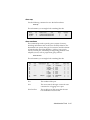
1
TM ENTERPRISE NETWORK HUB SYSTEM NETServer/8 NETServer/16 Version 3.1 Command Reference Copyright 1996 by U.S. Robotics Access Corp. 8100 North McCormick Blvd. Skokie, Illinois 60076 All Rights Reserved U.S. Robotics and the U.S. Robotics logo are registered trademarks of U.S. Robotics Access Corp., Total Control is a trademark of U.S. Robotics Access Corp. Any trademarks, tradenames, service marks or service names owned or registered by any other company and used in this manual are the property of their respective companies. ii Table of Contents Warranty and Service Chapter 1 Overview What’s New in 3.1? NETServer Overview Chapter 2 Basic Installation System Administrator Requirements Accessing the Command Line Getting Started Getting the LAN Port Up and Running Recommended Global Configuration Chapter 3 2-1 2-3 2-4 2-5 2-11 Configuration Overview How to Set Up Applications The Command Line Quick Command Overview Overview of Configurable Tables Chapter 4 1-1 1-5 3-1 3-3 3-5 3-6 IP Terminal Server Setup Terminal/Workstation Setup NETServer Setup (Overview) Using Default Hosts IP Terminal Server (Detailed Setup) Configuring a port Adding a Login User to the User Table IP Terminal Server Case Studies 4-1 4-2 4-3 4-4 4-4 4-9 4-12 iii Chapter 5 Network Dial-in Access Dial-In User Setup NETServer Dial-In Setup (Overview) NETServer Dial-In (Detailed Setup) Configuring a Port Adding a Network User to the User Table IP Remote Access Case Study IPX Remote Access Case Study Chapter 6 5-1 5-2 5-4 5-4 5-6 5-11 5-15 LAN-to-LAN Routing Setup for NETServer Routing (Overview) An Introduction to NETServer Routing PAP and CHAP Authentication LAN-to-LAN Routing (Detailed Setup) Configuring a Port Adding a Remote Device to the Location Table Adding a Remote Device to the User Table LAN-to-LAN Routing Case Study Testing the Connection 6-1 6-4 6-9 6-12 6-12 6-14 6-22 6-25 6-29 Chapter 7 Talking to the Modems TCP/IP Modem Sharing Implementing Security with Host Device Dial Out Configuring Modems as UNIX pseudo TTYs Modem Initialization Scripts Sending AT Commands Chapter 8 Packet Filters Packet Filter Overview Adding Packet Fitlers Filter Rule Format TCP/IP Rules TCP and UDP parameters Filtering ICMP packets IPX Packet Filtering SAP Rules Editing Packet Filters iv 7-1 7-3 7-4 7-6 7-9 8-1 8-4 8-6 8-8 8-10 8-15 8-16 8-18 8-19 Chapter 9 Administrative Tools Configuring the !root Account Manually Connecting to a Remote Site Troubleshooting Commands The SHOW commmand Chapter 10 9-1 9-3 9-4 9-11 Command Reference Global Configuration Hosts Table Configuration Location Table LAN Port (Net0) Configuration Netmasks Table Configuration Ports Table (S-port configuration) Routes Table Configuration SNMP Table User Table 10-1 10-13 10-14 10-24 10-30 10-31 10-49 10-54 10-57 Reference Section Appendix A Technical Specifications Appendix B Addressing Schemes Appendix C Software Download Appendix D The Boot Process Appendix E Syslog Accounting Appendix F RADIUS Security and Accounting Index v Warranty and Service Limited Warranty U.S. Robotics Access Corp. warrants to the original consumer or other end user purchaser that all U.S. Robotics Total Control products and parts are free from defects in materials or workmanship for a period of two years from the date of purchase. During the warranty period, and upon proof of purchase, the product will be repaired or replaced (with the same or similar model) at our option, without charge for either parts or labor. This warranty shall not apply if the product is modified, tampered with, misused, or subjected to abnormal working conditions. REPAIR OR REPLACEMENT AS PROVIDED UNDER THIS WARRANTY IS THE EXCLUSIVE REMEDY OF THE PURCHASER. THIS WARRANTY IS IN LIEU OF ALL OTHER WARRANTIES, EXPRESS OR IMPLIED, INCLUDING ANY IMPLIED WARRANTY OF MERCHANTABILITY OR FITNESS FOR A PARTICULAR USE OR PURPOSE, AND U.S. ROBOTICS SHALL IN NO EVENT BE LIABLE TO PURCHASER FOR INDIRECT OR CONSEQUENTIAL DAMAGES OF ANY KIND OR CHARACTER. Some states do not allow the exclusion or limitation of incidental or consequential damages or allow limitations on how long an implied warranty lasts, so the above limitations or exclusions may not apply to you. This warranty gives you specific legal rights, and you may also have other rights which vary from state to state. vi Service and Support To obtain service, contact the U.S. Robotics Systems Product Support Department as described below. Whichever method you use to contact us, please have the product serial number(s) available. Technical Support For technical assistance, contact USR in one of the following ways: Mail 8100 North McCormick Blvd. Skokie, Illinois 60076-2999 E-Mail [email protected] Toll-Free Line 800-550-7800 Fax 847-982-0823 BBS 847-982-5092 Fax on Demand 800-762-6163 America Online Keyword USROBOTICS CompuServe GO USROBOTICS Anonymous FTP ftp.usr.com* Username=Anonymous Password=your internet address. World Wide Web http://www.usr.com *The FTP is for downloading files only. If the support representative determines that you should send your equipment to USR for service, you will be given a Service Repair Order (SRO) number to help track your service request. Once you have received an SRO number, take or mail the product, postage prepaid, to U.S. Robotics at the above address. Include proof of the date of purchase. IMPORTANT: If you ship your unit, pack it securely, be sure your SRO number is visible on the outside of the package, and ship it charges prepaid and insured. vii We welcome your suggestions for better documentation Every effort has been made to provide useful, accurate information. If you have any comments or suggestions, please let us know. viii By voicemail: (708) 933-5200 Via the Internet: [email protected] Chapter 1 Overview This chapter provides an overview of the Total Control NETServer/8 and NETServer/16. It also contains information on what’s new in version 3.1 of the NETServer firmware. What’s New with Release 3.1? Release 3.1 supports the following new features: • Classless InterDomain Routing and Host-based routing via the Netmask Table. • IP address spoofing. • Support for RADIUS accounting servers, ANI/DNIS, and ICMP message logging. • Support for a secondary and a tertiary name server. • Randomized use of Default/Alternate Hosts for load balancing. • New Modem Port Features Additional Software Enhancements • NetBIOS over IPX support • PAP enable/disable • Pre-allocated system netbufs increased from 1000 to 1400 • Rezero network statistics and session statistics saved until next call • Unidirectional Van Jacobson compression • Users set to Prompt may specify a TCP port with the host name or IP address when using Telnet Overview 1-1 Netmask Table CIDR (Classless Interdomain Routing) or host-based routing requires special netmasks. Special netmasks may also be useful for debugging. The Netmask Table allows you to configure netmasks for CIDR or host-based routing as needed. RIP messaging/dynamic route information must be active for host-based routing. IP Address Spoofing The NETServer may now be configured to spoof a single IP address. When the NETServer identifies itself to remote routers or other remote devices, it uses this IP address rather than the IP address of its LAN interface. IP address spoofing is useful when more than one NETServer must appear to be a single router or other device to remote networks and other routers. Accounting Servers The NETServer supports the following new features: • Log accounting information to a RADIUS accounting server such as the security feature of U.S. Robotics Total Control Manager. • ANI and DNIS call information • Log ICMP error messages to a UNIX Syslog server Accounting Server Support The NETServer now supports event logging. You can configure the NETServer to send event information to a Total Control Accounting Server or a UNIX accounting server. You can also configure the NETServer to send the event information to an alternate accounting server if the primary server is unavailable. Event logging is performed by transmitting a record containing event information from the NETServer client to an accounting server. TCM uses the RADIUS client/server model for this feature. 1-2 Overview RADIUS Accounting and ANI/DNIS Release 3.1 of the NETServer supports the current RADIUS Accounting Internet Draft. The NETServer can generate appropriate Code 4 Accounting-Request and Code 5 Accounting-Response messages for properly configured RADIUS servers. The NETServer’s RADIUS implementation also supports ANI and DNIS services. ICMP Message Logging If your system uses syslog network accounting, you can configure the NETServer to send ICMP error messages to the syslog server. Multiple Name Servers Release 3.1 of the NETServer supports up to two name servers. The first is a primary name server, and the second is a backup server that is used when the primary name server is unavailable. Note: The NETServer does not support more than one name service at a time (DNS and NIS cannot both be running). Randomized Hosts You can now relieve the burden on frequently-used global default, port default and RADIUS user table hosts, by randomizing the selection of the host chosen for user sessions. When this feature is enabled, a preferred host will be randomly chosen from among the default and alternate hosts defined rather than always preferring the default host. Overview 1-3 New Modem Port Features Release 3.1 of the NETServer Command Line and NETServer Manager software now support the following modem port features: • Download new firmware to the modems using NETServer Manager (windows software) version 3.2 or later. • You can now send AT commands directly to the modems from the NETServer’s command line. • Detect and flush of stopped ports • Dialback delay • Port status display shows current and configured status • Ports reset if Carrier Detect is lost before a user connects to a host • Support for of up to eight Alternate Hosts 1-4 Overview NETServer Overview The NETServer allows you to implement four basic applications: IP Terminal Service, IP modem sharing, IP/IPX Network Dial In, and IP/IPX LAN-to-LAN routing. Everything else it does is based on one of these four. IP Terminal Service Remote terminals can log into an IP host on the NETServer’s local network as of they were physically connected to it. To do this, the NETServer receives TTY terminal output (keystrokes) over a dial up line. It then forwards the terminal output to the host using a virtual terminal protocol (login service) like Telnet or Rlogin. Since the connection is bi-directional, the terminal also receives the host’s responses. Overview 1-5 IP Modem Sharing Hosts on a local IP network can use a chassis modem to dial out. Moreover, the NETServer can create pools of modems that can be used by local hosts on a first come, first serve basis. To do this, the NETServer allows the host to establish a virtual terminal session with the modem. The host can then interact with the modem’s command line and from there, dial out. On a UNIX host, you can install a pseudo TTY driver that allows the host to interact with this virtual terminal connection as if it was actually a serial port. This makes the modem appear to be directly connected to the host. Network Dial In Access Remote IP and IPX users can dial in and attach to the local network as if they were local nodes. IP and/or IPX packets are transmitted over a dial in connection encapsulated in a serial line networking protocol (PPP or SLIP). When received by the NETServer, the IP and IPX packets are forwarded from the remote user to the LAN and vice versa. 1-6 Overview Dial-Up Routing The same routing engine that allows network dial in access allows the NETServer to establish dial up routing sessions with remote networks. Such connections can be maintained continuously or established on an on-demand basis and torn down when not needed. How do I get there from here? Configuring any of these applications on a NETServer is a threestep process: 1. Perform basic configuration for the NETServer. This includes configuring it to talk to your LAN and setting global user and global routing parameters. You can begin this process by going to Chapter 2. 2. Configure modem “S-ports” to support the application 3. Configure user table entries for dial in connections and IP modem sharing, location table entries for dial out routing. Steps 2 and 3 are covered by application in chapters 4 through 7. Overview 1-7 Security The NETServer supports IP and IPX packet filtering in both the inbound and the outbound directions of ports, users, and dial out locations. Packet filter configuration is discussed in Chapter 8. The NETServer also supports the use of a centralized RADIUS security server, allowing you to create a single account for each user rather than multiple user accounts on multiple NETServers. RADIUS security is discussed in Appendix F. Administrative Utilities The NETServer’s command line includes an assortment of utilities for troubleshooting connections including: • The ability to manually dial a location to test connectivity • The ability to use Telnet, Rlogin or PortMux to establish a session with another host from the NETServer’s command line. • UNIX-like troubleshooting commands including ifconfig, ptrace, ping and traceroute for debugging IP connections. These commands are contained in Chapter 9, along with instructions for customizing the supervisor account. 1-8 Overview Chapter 2 Basic Installation This chapter contains information on the following: • System Administrator Requirements • Logging into the supervisor account for the first time • Getting the LAN port up and running • Recommended Additional Configuration System Administrator Requirements In compiling this manual, we have had to make certain assumptions about the knowledge of users who will install the product. The documentation assumes that the system administrator is familiar with Novell networks and/or IP networks, as well as networks in general. Novell offers a variety of programs to certify administrators in network technology. TCP/IP information is available from a variety of sources, some of which are covered below. After reviewing this manual, users should decide if their ability is sufficient to handle the technical details of installation. If the assistance of a qualified professional is needed, we recommend that you consult with your nearest authorized U.S. Robotics Platinum reseller for advice. For a service fee, U.S. Robotics also offers qualified engineering assistance on site. Contact Systems Product Support at (800) 231-8770 for more information. Basic Installation 2-1 TCP/IP Reference Material It is the responsibility of the Network Manager to devise an addressing strategy appropriate for the size and growth potential of the network. We recommend the following reference material for TCP/IP: Comer, D.E., Internetworking with TCP/IP Volume I: Principles, Protocols and Architecture, Prentice-Hall, Englewood Cliffs, New Jersey, 1995. IP machines and networks that will be attached to the Internet must obtain registered addresses from the Internet’s Network Information Center. They can be contacted at the following address and phone number. Network Solutions InterNIC Registration Services 505 Huntmar Park Drive Herndon, VA 22070 1-703-742-4777 However, for networks with only a few IP machines, it is probably better to contact your local Internet access provider and let them handle the details. 2-2 Basic Installation Accessing the Command Line To configure the NETServer from the command line, you must log in as the supervisor. 1. In order to login, you need a login prompt. There are three ways to get one: • Attach the provided serial cable to the CONSOLE port and attach the other end of the cable to a terminal (or a PC running terminal emulation software such as Windows Terminal). See the Quick Start Guide for more information. • Using communications software, dial into any modem port that is configured to support user login or network dial in (by default, they all are). The data format is 8 data bits, 1 stop bit and no parity (8-N-1). • If you have configured the LAN port (Ethernet interface) to communicate with a local TCP/IP network, you can Telnet to the NETServer using the address assigned to this port. For information on configuring the LAN port, see Getting the LAN Port Up and Running, later in this chapter. Note that if you are just turning the NETServer on, it may take a few seconds after the NETServer begins to boot before the login prompt appears. If the login prompt does not appear, try hitting the Enter key. 2. Login as the supervisor/superuser by typing the following: !root Enter (Must be all lower case!) 3. The password prompt appears. The default is no password at all. If you have changed the password for the !root account, type the new password in and press the Enter key. Otherwise, just press Enter 4. The “Command>” prompt appears. The NETServer is now ready to be configured. Basic Installation 2-3 Getting Started Name your NETServer. Among other things, this name will be used for the NETServer’s DNS system name and its SNMP system name. It is also the name that the NETServer will advertise in SAP broadcasts. No other device on your network should be using this name. Use the following command: set sysname <name (up to 32 characters)> Enter The next thing you need to do is get your NETServer talking to the network attached to its LAN port. This section below titled Getting the LAN port up and running contains the minimum configuration needed to allow the NETServer to talk to your Ethernet or Token Ring LAN. Keep in mind that these may not be the only parameters you’ll want or need to set—just the ones you must set. A complete listing of LAN port parameters can be found in Chapter 10. Once you have configured the NIC interfaces, we recommend that you proceed to global configuration. The parts of this that most administrators will want to do right away can be found later in this chapter under Recommended Global Configuration. A more complete listing of global parameters can be found in Chapter 10. 2-4 Basic Installation Getting the LAN port up and running First step for IPX or IP/IPX networks If your network uses the IPX protocol, you must enter the IPX network number of the segment the NETServer connected to the NETServer’s LAN port. You can find this network number using Novell’s CONFIG utility. For File Servers Running Novell Version 3.xx 1. Go to the console of a file server that is on the same network segment that the NETServer is on. 2. From Novell’s Console program press CTRL-ESC, then ESC, until the : (colon) prompt appears. Select System Console and press the Enter key. 3. Type the following: CONFIG Enter A display similar to the one shown below appears: File server name: USR_SERVER_ONE IPX internal network number: 0000000A Western Digital Star EtherCard PLUS Driver v2.05 (910424) Hardware setting: I/O Port 300h to 31Fh, Memory CC000h to Cffffh, Interrupt Ah Node address: 0000C0488D28 Frame type: ETHERNET_802.3 Board name: TENBASE_802.3 LAN protocol: IPX network 00000255 Western Digital Star EtherCard PLUS Driver v2.05 (910424) Hardware setting: I/O Port 300h to 31Fh, Memory CC000h to Cffffh, Interrupt Ah Node address: 0000C0488D28 Frame type: ETHERNET_802.2 Board name: TENBASE_802.2 LAN protocol: RPL LAN protocol: IPX network 00000684 Basic Installation 2-5 This is an example of the information returned for one version 3.xx card that has two different frame types. The card has one port address, but two LAN protocol network addresses, one for each frame type. The network number for 802.3 is 00000255, and for 802.2 it is 00000684. 4. Write down the LAN protocol IPX network number for the frame type you want to use. For File Servers Running Novell Version 2.xx 1. Go to the console of a file server that is on the same network segment that the NETServer is on. 2. Press CTRL-ESC until the : (colon) prompt appears. 3. Type the following: CONFIG Enter A display similar to the one shown below appears: LAN A Configuration Information: Network Address: [0788] [002608C0D53F4z] Hardware Type: [3Com 3C505 EtherLink Plus (Assy 2012 only) V2.30EC (880813)] Hardware Setting: IRQ=5, IO=300h, DMA 5 The above example only has one frame type, so the network address is 0788. 4. Write down the network address for the frame type you want to use. 2-6 Basic Installation IP Configuration 1. IP Network Address: You must assign an IP address to the NETServer’s LAN interface (Ethernet or Token Ring port). Type the following: Enter set net0 address <IP address> If your network does not use IP, you may choose whatever address you like. See Appendix B for some basics on TCP/ IP addressing. However, if you want to connect the NETServer to the Internet (even indirectly), the address must be unique in the world. To obtain such an address, contact your local Internet service provider. If you need a large number of IP addresses, you may want to contact the InterNIC (see the beginning of this chapter for their address). Example: set net0 address 192.77.203.200 Enter 2. You must set the LAN port’s subnet mask. The default is 255.255.255.0, which would be appropriate for a Class C network with no subnetting or for Class C size subnets of larger networks. You must change this value if the network attached to the NETServer’s LAN port uses a different subnet mask. To change the Netmask, type the following: set net0 netmask <netmask> Enter Example: set net0 netmask 255.255.255.0 Enter Basic Installation 2-7 3. You must also set the Broadcast Address. Type the following: set net0 broadcast <high or low> Enter High The bits of the host portion of a broadcast address are all ones. This is the rule for the vast majority of IP networks. Low The bits of the host portion of a broadcast address are all zeroes. This is rare, but is still used by some systems including Sun OS 4.x (Solaris 1.x). For example, the node 192.77.203.7 uses the default subnet mask of 255.255.255.0, which would give it a high broadcast address of 192.77.203.255 and a low broadcast address of 192.77.203.0. To use the address ending in 255: set net0 broadcast high Enter 4. If your network does not use the IPX protocol, you may now go to Final Steps. Otherwise complete the steps in the next section, IPX Configuration. 2-8 Basic Installation IPX Configuration IMPORTANT: Even if your network uses only the IPX protocol, you must set up an IP address for the NETServer if you want to use the Windows-based management software. If you have not already done so, perform step 1 under IP Configuration. 1. IPX Network Frame Type: This is the IPX frame type of the network segment connected to the NETServer’s LAN port. Enter set net0 ipxframe <frame type> Valid frame types are: ethernet_802.3 ethernet_802.2 ethernet_802.2_II ethernet_II Example: set net0 ipxframe ethernet_II Enter 2. IPX Network Number: This is the network number of the network segment connected to the NETServer’s LAN port. Note that the same physical network segment will have a different network number for each frame type used. Be sure to select the network number associated with the frame type selected above. Type the following: set net0 ipxnet <network number> Enter <Network Number> is the number you obtained by following the instructions titled First Step for IPX Networks. If you have not already obtained this number, do so now. Example: set net0 ipxnet 00000684 Enter Note that the preceding 0’s in this example could have been omitted. The NETServer would have accepted “684” as the correct IPX Network Number and filled in the preceding 0’s. Basic Installation 2-9 Final Steps Save your configuration and reboot the NETServer. Note that the LAN port settings are the only configuration changes that will require rebooting the NETServer. To save your changes, type the following: save all Enter Wait until the RN/FL LED is green. Rebooting the NETServer while a save is in progress could cause the flash memory to be corrupted. When the LED is green, type the following: reboot Enter Note that the NETServer may respond with a command prompt to indicate that it has received the reboot command, but you will not be able to access the NETServer until it finishes rebooting. When the NETServer finishes rebooting, the login prompt will reappear. From this point on, configuration can also be done from the Windows-based NETServer Manager software. If you would rather configure the NETServer from Windows, proceed to the Installation and Recommended Configuration sections of the NETServer Windows Software Guide. 2-10 Basic Installation Recommended Global Configuration Following is a list of global fields that we recommend you configure. Password This is the password for the superuser (supervisor) account. If a password has been set, it must be entered when logging into the NETServer from either the command line or from the Windowsbased software. The default is none. The password can be any combination of up to 15 ASCII characters. Type the following: set password <password> Enter Do not forget your password. If you do you will have to erase all configuration information saved in flash memory - set DIP switch #4 in the bottom row of DIP switches ON (down) and reboot the NETServer. If you do not have your NETServer’s configuration saved to disk (using the NETServer Windows software), you will have to start all over again. IP and IPX Default Gateways If the NETServer does not know where to send a packet, it forwards the packet to the default gateway or router defined in this step. Default gateways must be on the same subnet as the NETServer. You must also enter a metric (hop count) for each type of default gateway. Possible values range from 1 (default) to 15. Note that since the actual metric of a default gateway is only 1 hop, the value entered here is used to control the perceived cost of the gateway to other routers on your network. For example, a high metric will limit the number of hops that the route is broadcast and may cause other routers to see it as a less preferable route. If the NETServer is configured to listen for IP default route broadcasts (see Global Configuration, Default Route in Chapter 10), the IP Default Gateway can be overridden by a default route broadcast with a lower hop count. Basic Installation 2-11 To set the IP gateway, type the following: Enter set gateway <IP address> <metric> The following example configures an IP default gateway whose cost is prohibitive to all but the closest subnets: set gateway 192.77.203.200 12 Enter To set the IPX gateway, type the following: set ipxgateway <IPX node address> <metric> Enter The IPX node address is the full hex IPX node address, in other words: 8 digit network number:12 digit node MAC address The following example sets up a default gateway on network number A34. Note that the preceding zeros could be omitted: set ipxgateway 00000A34:000000123456 1 2-12 Basic Installation Name Service This is the server that translates your host names into their corresponding IP addresses.. The NETServer supports two types of name servicesDNS and NIS. NIS is also sometimes referred to as Yellow Pages (YP). If you are using DNS, type set namesvc DNS Enter If you are using NIS, type set namesvc NIS Enter You must also identify the name server and domain name used by the name service. The name server (the computer responding to name service queries) is indicated by its IP address. The domain name is the domain that the NETServer belongs to. Type the following lines. Follow each with the Enter key. set nameserver <IP address> set domain <domain name> Note: The name server will only be consulted to resolve host names not found in the hosts table. If you are using a name service, the hosts table may be left empty. Save your work Once you are done setting the desired parameters, you can save your changes to flash memory by typing the following: save all Enter Basic Installation 2-13 2-14 Basic Installation Chapter 3 Configuration Overview The internal firmware lets you manage and configure the NETServer by typing commands. This chapter covers the following: • How to set up applications • Issuing commands • Quick Command Overview • Overview of configurable tables How to Setup Applications There are three applications the NETServer is designed to handle: user dial in access, modem sharing, and LAN-to-LAN routing. All other applications are variations on one of these. Applications - Each modem can be configured for one or more of these User Dial In Access IP Modem Sharing LAN-to-LAN Routing Configuration for each of these applications is a two step process: 1. Configure one or more modems to support the application. Note that modem ports may be configured to support multiple applications at the same time. 2. Add user table or location table entries or both, depending on the application. Configuration Overview 3-1 Where do I go from here? Each of the three applications has a section of this manual devoted to its setup. If you want to begin configuration immediately, you may go to one of the chapters listed below: Application Section User Dial In Access Chapters 4 and 5 LAN-to-LAN Routing Chapter 6 IP Modem Sharing Chapter 7 Note that there are actually two Chapters for user dial in access. They cover two very different types of user: login users and network dial in users. Login Users These are users requesting terminal access to an IP host. They dial into the NETServer and are connected to the requested host with a login service such as Telnet or Rlogin. Note that these users don’t need an IP address, since they aren’t actually attaching to the network. (See Chapter 4 for setup) Login Users Terminal-style login using a service such Dial In Users as Telnet or Rlogin Network Dial In Users Use PPP or SLIP to become a virtual node of the network (See Chapter 5 for setup) Network Dial In Users These users actually pretend to be nodes, complete with addresses, on the network. They do this by using PPP or SLIP to send network packets over the phone lines. Since all IPX users attach to the network and have addresses, All IPX users are of this type. 3-2 Configuration Overview The Command Line The Command Line Interface is similar to DOS, UNIX or Netware in that you can type commands to view information, change settings and so on. Commands are not case sensitive You can type any command in upper or lowercase. Table entries are case sensitive, however. For example, “SASHA,” “Sasha” and “sasha” are three different users (or locations). You can abbreviate commands You can abbreviate most commands and command options with the first two or three letters that distinguish that command from any other command. For example, you need only type set net0 addr to set the NETServer’s IP address (the full command is set net0 address). IMPORTANT: Make sure that your abbreviation is long enough to distinguish the command from any similarly spelled commands. For example, if you typed IPX to set the IPX network number, you’ll get an error message. This is because you could be referring to any one of the following commands: ipxnetwork, ipxgateway, or ipxframe. Separate a parameter and its value by a space Do not use an equal sign ( = ) or any other punctuation mark between a parameter and the value to be set. For example, you should type the following: set user fredb service netdata Enter You should not type the following: set user fredb service=netdata Enter Configuration Overview 3-3 Save your changes You can save all of your changes, or you can save changes to a specific table only. Note: We recommend using save all. If you save tables individually, the space used by the previous version of the table is not freed up. Issuing the save all command frees up any unused space before saving. save all save s<port #> save filter save global save host save ipxroute save location save netmask save routes save snmp save user save all configuration data save a port’s configuration save all of the packet filters save the global table save the hosts table save the IPX routes table save the location table save the netmask table save the IP routes table save SNMP configuration save the User Table Reset any ports you have changed If you make changes to any port, you must reset the port before the changes take effect. This will close any active connections on the port!!! reset all S-ports (s0 through s16) reset s<port #> a specific S-port reset n<connection handle> an active connection (find handle with show netconns) Reboot when necessary The only changes that require rebooting the NETServer are changing its LAN port (Net0) configuration. If you change the Net0 configuration, save your work and then type the following command: reboot How to log out of the command line When you are done configuring the NETServer, you may exit the command line interface by typing done, exit, or quit. 3-4 Configuration Overview Quick Command Overview The NETServer’s configuration data is stored in several tables, including the user table and the location table among others. To change most parameters in these tables, use the set command: set <user | location | port | etc.> <parameter name> <value> For example: set net0 address 192.77.203.5 set user John password Bumblebees Some things, like individual locations and users, must be created before they can be configured. The following command is used: add <user | location | filter | etc> <name> Names are case sensitive!!! Note that anything that can be added can also be deleted. delete <user | location | filter | etc.> <name> You can view current configuration information using the show command. For example: show net0 show user John show ipxroutes A complete listing of commands and options may be found in the back of the Quick Start Guide. Help for any of these commands is available using the help command. For example: help set help set user help add help delete help show Configuration Overview 3-5 Overview of configurable tables This section contains a brief description of each of the NETServer’s internal databases. Global Configuration The Global Configuration table lets you configure parameters that apply to all ports, such as the Name Service (if any) your network uses, default gateways through which to forward packets, and so on. You can also set the Global Default Host that login users may establish a session with, as well as the NETServer’s password. RADIUS Configuration The Global Configuration table also allows you to designate a RADIUS security server. A RADIUS security server will allow you to maintain users in a single, centralized users file rather than updating the users tables for several different NETServers independently. You may also specify a RADIUS network accounting server. Hosts Table The Hosts Table is a list of local hosts. The table is used to translate names to IP addresses and vice versa. This allows users and administrators to type host names rather than addresses. This is especially useful if the network does not have a name service such as NIS or DNS. If your network has a name server, the NETServer tries to match the host name with an IP address using the Hosts Table before using the name server. Note that IPX networks do not use this table since SAP automatically provides the functionality of a name service. 3-6 Configuration Overview Initialization Script Configuration A Port Initialization Script is a string of text that is sent to a modem (or S0, the external serial port) each time the port is reset (a modem resets itself every time it disconnects). Initialization scripts for the modems will probably contain the AT commands needed to configure them for use on your network. Location Table The location table stores information about remote sites that the NETServer needs to dial out to. The table is used during LANto-LAN routing, to tell the NETServer how to dial out to and communicate with a remote location. It is also used for dialing back network dial in users. Each location is configured with parameters such as what addresses and which protocol to use for the connection. A dial script for each location contains instructions on how to dial out to and sometimes even how to log into a remote host. Net0 (LAN Port) Configuration The Net0 Port Configuration table configures the LAN Interface. These settings reflect how the LAN attached to the NETServer is configured and include, for example, what protocol the LAN is using (IP, IPX, or both). Netmasks Table The netmasks table is used when you want to employ Classless InterDomain routing (also called Supernetting). Supernetting is a specialized IP addressing technique used by some Internet service providers. The technique requires that special netmasks be defined using the netmasks table. See Appendix B For more information on supernetting. Configuration Overview 3-7 Packet Filter Table Packet filters may be created to control which packets are permitted to pass through given interfaces. Packet filters created in the Packet Filter Table screen are used in the following Tables: • Net0 (LAN port) Configuration—to control what packets may pass through the LAN interface to the local network (output filter) or from it (input filter) • Location Table—to control what packets are received from the remote location (input filter) and what packets are sent to it (output filter) • Ports Table—to control what hosts a user can access, or if the port is set to Hardwired, to control what packets are received from the remote location (input filter) and what packets are sent to it (output filter) • User Table—for a Login User, to control what hosts the user can access, or for a Network User, to control what packets are received from the remote location (input filter) and what packets are sent to it (output filter) 3-8 Configuration Overview Port Configuration Port Configuration controls the modem ports and the external serial port. The configuration of these ports reflect what applications a given modem can be used for. Port Type Three fields determine which type of services a modem will support: User Login, Host Device, and Network. The default configuration is: Host Device Disabled User Login Enabled Network Dial In User Login A user login port services login users. As explained at the beginning of this chapter, login users are provided terminal access to hosts on the network, but do not actually become nodes on the network. Host Device Host device ports are used for IP modem sharing. A TCP port number is assigned to the modem, allowing users and applications to talk directly to its command line. Network Network ports are used for routing network (IP and IPX) packets via a serial communications protocol (PPP or SLIP). Both LAN-to-LAN routing and network dial-in users require this kind of connection. There are three types of network port: dial in, dial out and hardwired. A fourth setting, network twoway, allows both dial in and dial out service. Dial In Network dial in ports service network dial in users and remote routing devices that dial in to form a routing connection. Dial Out Network dial out ports are used to initiate dial up routing connections and to dial back network dial in users. Configuration Overview 3-9 Hardwired A hardwired port is a serial port that is connected directly to another device via a serial cable (this is only possible on S0). Note that both Host Device and User Login must be disabled on Hardwired ports. Routes Table The routes table contains both static and dynamic routing information. Dynamic routes are updated by RIP broadcasts received from other routing devices on the network. Static routes are routes added to the table by hand. A static route to a given location will override a dynamic route that RIP generates. Static routes to a given location are required when the location is not running RIP or when the NETServer is not listening for RIP broadcasts on the given interface. Without RIP protocol messaging, the NETServer cannot gather information on the location of other routers, gateways, and remote hosts and must know exactly where to send a packet. See An Introduction to NETServer Routing in Chapter 6 for an overview of the routing process. SNMP Configuration The NETServer provides support for the Simple Network Management Protocol (SNMP) and industry standard MIB-II variables. These variables are fully described in your MIB-II documentation. The SNMP Configuration commands let you configure what SNMP servers (if any) are permitted to make SET and GET requests, as well as what Read and Write Communities. 3-10 Configuration Overview User Table The User Table contains authentication and configuration information for two types of users: Login Users and Network Users. Note that you cannot have a Login User with the exact same name as a Network User. Login Login users are remote users dialing in to request terminal service from an IP host. Once such a user is authenticated, he or she is connected to a host with a login service such as Telnet or Rlogin. Network Network users are remote users dialing in to become a virtual node of the local network. Such a user may be an individual attaching to the network or an entire LAN dialing in to route packets onto the local network. Keep in mind that entries in the user table will usually override the settings for the port the user is connected to. Configuration Overview 3-11 3-12 Configuration Overview Chapter 4 IP Terminal Server Setup If you have workstations or terminals at a remote site that require access to a host on the local network, you can configure the NETServer to function as a terminal server. Terminal or Workstation Setup A. The remote user should get the following information from the NETServer’s system administrator: • The user name and password that he or she will use. • The telephone number of the NETServer the user must dial into. • If the terminal or workstation user will be able to choose which host he or she will log into for a given session, the IP address or name of each possible host must also be known. B. The dial in workstation or terminal should be configured for the following communications parameters: • 8 bits, No parity, and 1 stop bit • Hardware (RTS/CTS) flow control • Normal Carrier Detect • Hang up and reset when DTR drops Note that although these settings are the defaults, you can change the NETServer’s communications parameters if you want to. See Port Configuration, Serial Communications Parameters in Chapter 10 and your modem reference material for more information. IP Terminal Server Setup 4-1 NETServer Terminal Server Setup (Overview) A. Find out what kind of terminals are being used (or what kind of terminal will be emulated). If you don’t know the terminal emulation to use, you can also choose to go with standard Network Virtual Terminal emulation (ASCII only dumb terminal). B. Make sure that the hosts support the login service(s) that you will use to log into them. Virtually all IP machines support Telnet. Rlogin is standard to most UNIX machines and has spread to some other IP machines. PortMux requires that a host have the PortMux daemon (in.pmd) running. You can find the PortMux daemon on the U.S. Robotics web site. A fourth service, Netdata, does not require that the host be running a “Netdata” service. Instead of talking to such a service, Netdata (also called Clear TCP ) exchanges data directly with a given port number on the host. Netdata does, however, require that the specified TCP port number actually be an accessible process or device on the host. C. Configure a port for a connection. See Configuring a Port, later in this chapter. This includes setting a default login service and default hosts for the port, as well as configuring a login message (banner) and login prompt. The default login message is none, or no login message. The default login prompt is login:. D. Create a user entry in the User Table for the remote user. See Adding the Login User to the User Table, later in this chapter. A login user table entry defines a host and login service for an individual user. 4-2 IP Terminal Server Setup A Note About Hosts When a login user dials in, he or she is forwarded to a host. Which host the user is forwarded to depends on several things. The NETServer first attempts to find host information in the individual’s user table entry. If the user table shows a host of Default, the NETServer checks the host setting for the port the user is connected to. User Table set user <name> host <default | prompt | IPaddress> default Port Default set s<port #> host <default | prompt | IPaddress> default Global Default set host <IP address> If the port shows a host of Default, the NETServer uses the Default Host defined in Global Configuration. Note that it is possible that no host will be defined in any of these places. If this is the case, the NETServer will return to the login prompt. The user will not be allowed to log in unless he or she enters a user name/password for a user with a host defined. IP Terminal Server Setup 4-3 Terminal Server (Detailed Setup) The following section give details on configuring the NETServer as a terminal server from the command line. For instructions on how to attach to the command line software, see Connecting to the Command Line in Chapter 2. Configuring a Port Ports used for terminal service must be configured as User Login ports. Step 1 - Set the port type to User Login The following command configures a port for terminal service: set s<port #> login Step 2 - Set the port’s security (Pass-Thru Login) This setting determines what the NETServer will do with users who are not in its User Table. You can turn security on or off. On If a user does not enter a user name/password pair that can be found in the NETServer’s user table, check with the RADIUS security server (if present). The connection is terminated for all users who are not in either the NETServer’s user table or the RADIUS database. Use the following command: set s<port #> security on Off (Default) Do not consult RADIUS. Anyone dialing in to this port who does not enter a valid user name and password will be connected directly to the Port Default Host without being authenticated. set s<port #> security off 4-4 IP Terminal Server Setup Step 3 - Create default user settings for the port If you turned security off in Step 2, port defaults must be set to tell the NETServer what to do with users not in the user table. If security is on, these settings are optional. Users who are in the NETServer’s user table may also use some of these settings. Port Default - Host The port default host is for users not in the user table and for users whose user table entries specify a host of Default. You may choose a host of Default, Prompt, or a specific IP address. Use the following command: set s<port #> host <host type> Default Users are passed on to the Default Host defined in the Global Configuration table. (Default) If the Global Default Host is not available, users are passed on to one of the Global Alternate Hosts (if specified). set s<port #> host default Prompt As soon as a user connects with the NETServer, he or she is given a Host: prompt. Users type the name or IP address of the host they want. Note that since the host prompt appears before the login prompt (before the NETServer knows who the user is), even users who have a host specified in the user table will be prompted for a host. However, a host specified in the user table will always override the value entered here. set s<port #> host prompt IP Address Users are connected to a specific host other than the default host. Type in the IP address of the specific host. set s<port #> host <IP address> IP Terminal Server Setup 4-5 Port Default - Login Service The NETServer uses the service specified here to connect users not in the user table with the port default host. Users with user table entries will not use this setting This setting is never used when Security is set to On. Note that the remote terminal or workstation does not need to know how to use this service since it talks directly to the NETServer, not the host. Use the following command: set s<port #> service_login <login service> <TCP port#> <TCP port#> is the port number on the host you want to connect to. It is optional unless you choose Netdata as the login service. <login service> is one of the following: 4-6 Telnet Supported by most TCP/IP computers, Telnet lets the user log in to hosts that support it. If you set a terminal type (see Term Type below), Telnet will pass that information along. Otherwise, it negotiates a standard, Network Virtual Terminal interface. Rlogin Although Rlogin was originally a (BSD) UNIX only protocol, it is now supported by some non-UNIX machines as well. Unlike Telnet, Rlogin allows a user logged into a host, to access their accounts on other (trusted) hosts without reentering a password. Rlogin requires that you specify a terminal type. See Term Type below. PortMux (Default) PortMux is similar to Telnet except that it multiplexes many Telnet sessions into a single data stream that’s more efficient to transmit and requires fewer connections. PortMux requires that the host be running a special PortMux daemon (in.pmd). Note that this daemon also allows the host to use NETServer ports set to Host Device as pseudo TTYs (See Chapter 7). The PortMux daemon is available on the U.S. Robotics web site. Netdata Unlike Telnet, Rlogin and PortMux, Netdata is not actually a login service. Netdata is a direct (clear TCP) connection to a given TCP port number. 8-bit data is exchanged without interpretation. Such connections may be used by dial in applications that require a socket interface. IP Terminal Server Setup Port Default - Terminal Type: This value is used by all login users connected to this port. The purpose is to inform the host what kind of terminal is being used (or emulated). by users connecting to this port. The field is a string of characters that must be recognized by the host as a valid terminal type. Valid terminal type strings for a UNIX host are stored in a database called termcap or terminfo. Specifying a terminal type is only required if Login Service is set to Rlogin However, Telnet and PortMux will also use this value if one is entered. If no terminal type is entered, Telnet and PortMux will assume dumb terminal mode (standard Network Virtual Terminal). Use the following command: set s<port #> termtype <emulation> Step 5 - Optional Friendly Stuff The following two parameters allow you to customize the port’s printed response to dial in users. Login Message You can create a message (banner) that users will see prior to login. Use the following command: set s<port #> message <login message> The login message can be up to 240 characters in length and does not need to be surrounded by quotation marks (if you use quotes, they will be included in the message). Use the carat ( ^ ) to designate the start of a new line. Example: set s24 message U.S. Robotics^NETServer Login Prompt The following command allows you to customize the login prompt for the port: set s<port #> prompt <login prompt> If you put the word $hostname in the prompt, the NETServer will substitute the name of the port’s default host. The default prompt for user login ports is $hostname login:. If you use quotation marks, they will be included in the prompt. IP Terminal Server Setup 4-7 Many automated login scripting systems expect a login prompt to end in login:. Putting any character after the colon (including quotation marks!) will cause some login scripts to crash. If you select Telnet as the Port Default Login Service, the NETServer changes the login prompt to “Press <Return> to begin logging in”. If you would prefer to use a different login prompt, type the new prompt using this command. Step 6 - Save your work Save your changes to flash memory. Use the following command: save s<port #> Reset the port so that the changes take effect. Use the following command: reset s<port #> 4-8 IP Terminal Server Setup Adding a Remote User to the User Table Users for terminal server applications are configured as login users. Step 1 - Add the user to the User Table Type the following command: add user <name> password <password> Step 2 - Configure the user You must specify a login service for each user. Specifying a host for each user is optional if you have either a port default or a global default host defined. Host This tells the NETServer which host the user will be logging in to. Use the following command: set user <name> host <host type> <host type> is default, prompt or a specific IP address Default (Default) The user is passed on to the default host for the port he or she is connected to. set user <name> host default Prompt The user is given a Host: prompt. Users type the name or IP address of the host they want. Note that if the port default host type is also prompt, the host prompt appears before login. Otherwise, the host prompt appears after login. set user <name> host prompt IP Address The user is connected to a specific host other than the default host. Type in the IP address of the specific host. set user <name> host <IP address> IP Terminal Server Setup 4-9 Login Service The NETServer uses the service specified here to connect the user to the selected host. Note that the remote terminal or workstation does not need to know how to use this service since it talks directly to the NETServer, not the host. Use the following command: set user <name> service <service> <TCP port #> <TCP port#> is the port number on the host you want to connect to. It is optional unless you choose Netdata as the login service. <service> is one of the following: 4-10 Telnet (Default) Supported by most TCP/IP computers, Telnet lets the user log in to hosts that support it. If you set a terminal type for the port the user connects to, Telnet will pass that information along. Otherwise, it negotiates a standard, Network Virtual Terminal interface. Rlogin Although Rlogin was originally a (BSD) UNIX only protocol, it is now supported by some nonUNIX machines as well. Unlike Telnet, Rlogin allows a user logged into a host, to access their accounts on other (trusted) hosts without reentering a password. Rlogin requires that you specify a terminal type for the port the user will dial into. PortMux PortMux is similar to Telnet except that it multiplexes many Telnet sessions into a single data stream that’s more efficient to transmit and requires fewer connections. PortMux requires that the host be running a special PortMux daemon (in.pmd). Note that this daemon also allows the host to use NETServer ports set to Host Device as pseudo TTYs (See Chapter 7). A UNIX version of the PortMux daemon is available on the U.S. Robotics web site. Netdata Unlike Telnet, Rlogin and PortMux, Netdata is not actually a login service. Netdata is a direct (clear TCP) connection to a given TCP port number. 8bit data is exchanged without interpretation. Such connections may be used by dial in applications that require a socket interface. IP Terminal Server Setup Step 3 - Configure for dialback use? Normally, after a user enters his or her user name and password, the connection to the host proceeds. When a dialback user enters his or her user name and password, the NETServer hangs up and dials the user back. To configure a dialback user, type the following command: set user <name> dialback <number > <number> can be any valid string of up to 32 characters. If you want to use AT commands in this string, begin the string with “AT”. Otherwise, the NETServer will expect only a phone number. The two lines below actually do the same thing. The difference is that other AT commands could also be inserted in the second line. set user smiley dialback 5551000 set user smiley dialback atdt5551000 To clear the dialback entry and return the user to normal dial in service, type the following: set user <name> dialback none Step 4 - Save your work Type the following command: save user IP Terminal Server Setup 4-11 IP Terminal Server Case Studies The following examples set up users to log into the two hosts in the illustration below. IP Terminal Server - Case Studies Example 1 UserA, UserB, and UserC are all Login Users with entries in the user table. An application on VAX1 is connected to a dial-up information database that is open to the public (those not in the user table). Before you begin Make sure the NETServer is properly configured. • the NETServer must have an IP address assigned to it • the NETServer’s netmask must match the one being used on the local network. See Minimum Configuration in Chapter 2 for instructions on how to set these parameters. 4-12 IP Terminal Server Setup This example also assumes that Sun1 is the NETServer’s global default host. The command to do this is: set host 192.77.203.2 Port Setup The NETServer will use ports 6, 7, and 8 for this application. set s6 login set s7 login set s8 login Ports 6 and 7 will be used exclusively by users who already have user accounts. We want the NETServer to perform its own security checks and hang up on anybody not in the User Table or in the RADIUS server’s database. Note that since we have three user accounts but only two ports used for this purpose, only two of the three users may be logged in at any one time. set s6 security on set s7 security on Users connecting to these ports will be logging into Sun1 unless their user table entries specify a different host. Sun1 also happens to be the NETServer’s global default host. set s6 host 192.77.203.2 (Sun1’s IP address) set s7 host default (Sun1 could also be specified this way) By default, these users will be logging in with terminals emulating VT100s. Note that since security is on for this port, you should not specify a port default login service. The NETServer would never use such an entry. set s6 termtype VT100 set s7 termtype VT100 Port 8 will be used as a public information line. We want anybody to be able to dial into it. set s8 security off IP Terminal Server Setup 4-13 Users connecting to the info line will be connected directly to a database application running on VAX1 and will have no other access to VAX1. Note that since netdata is talking directly to an application, it will not relay terminal type information to the host. Instead, it will relay exactly what the application outputs. set s8 host 192.77.203.3 (VAX1’s IP address) set s8 service_login netdata 6020 (Connect directly to application at TCP port# 6020) User Table Setup User A will be logging in to Sun1 with Rlogin. Since Sun1 is the port default host, User A needs only a User name, a password, and a login service in the User Table. add user UserA password UserAPw set user UserA service rlogin User B can log into either SUN1 or VAX1. After he or she types the correct user name and password, User B will be prompted for a host name or IP address. User B will use the default login service, Telnet. add user UserB password UserBPw set user UserB host prompt UserC is a dialback user. When he or she enters the correct user name and password, the NETServer will hang up and dial the user back at 9, 555-1000. User C will use the port default host (Sun 1) and Telnet. Note that the password does not have to be defined on the same line as the user name. add user UserC set user UserC password callmeback set user UserC dialback 9,555-1000 Save your work and reset all the ports save all reset all 4-14 IP Terminal Server Setup Example 2 Suppose you have a lot of potential users, but only a couple of hosts, each of which has its own login security already set up for each of its potential users. It may be easier to assign generic user names for each host and let the hosts take care of user authentication. In this example, SUN1 is a generic user name for users of a Sun host. VAX1 is a generic user name for users of a VAX host. set s6 prompt Which Computer? set s7 prompt Which Computer? set s6 security on set s7 security on add user SUN1 set user SUN1 host 192.77.203.2 set user SUN1 service telnet add user VAX1 set user VAX1 host 192.77.203.3 set user VAX1 service telnet save all reset all When dialing into the NETServer, the user receives a “Which Computer” prompt. If the user enters SUN1, a connection is established with the Sun, which proceeds to authenticate the user with its own security info. Since no terminal type has been defined for the serial ports, all users will be defaulted to dumb terminal emulation. The same would be true of the VAX. IP Terminal Server Setup 4-15 4-16 IP Terminal Server Setup Chapter 5 Network Dial In Access Network dial in users establish PPP or SLIP connections with the NETServer and the local network. Unlike the “login users” covered in the previous chapter, this kind of user is connecting to the network as a virtual node rather than simply acting as an input/output device (terminal) for an existing network node. IPX dial-in users are all of this type. Dial-in User Setup The instructions below are required by all remote users dialing in to the NETServer. 1. The remote user’s computer must have communications software that supports PPP or SLIP connections. 2. A PPP or SLIP protocol driver must be loaded on the remote user’s computer for PPP or SLIP connections. 3. Set the modem to 8 data bits, No parity, and 1 stop bit. Note: These are the default settings only. If you want to, you can change what communications settings the NETServer uses on each port. See Port Configuration, Serial Communications Parameters in Chapter 10. Network Dial In Access 5-1 NETServer Setup for Network Dial-In (Overview) This setup configures a NETServer for users to dial in to. Note: This is a special case of LAN-to-LAN routing in which the dial in network has only one node (an end user). For a more complete understanding of how the NETServer handles these functions, you may want to study Chapter 6 as well Prework Get the following information (Note that not all settings apply to all applications): IP Parameters • The dial-in user’s IP address. Note that if the dial-in user’s IP address is not important, the NETServer may be told to simply assign the user an address each time he or she dials in. The address can also be negotiated by the NETServer and the user’s machine. • The connection protocol (PPP or SLIP) that the user will employ. • The dial-in user’s subnet mask. • The dial-in user’s Maximum Transmission Unit (MTU, the largest packet size that the system will transmit) if applicable; both local and remote MTU’s must match. • Whether or not the dial-in user is configured for Van Jacobson compression. IPX Parameters IPX remote access sessions must use the PPP protocol and an MTU of 1500. Note that when you assign an IPX Network number to the user, the NETServer will automatically set these things for you. Get the following information: • A unique IPX Network Number that will represent the link between the remote user and the local network for the duration of the connection. 5-2 Network Dial In Access Configuration A. Configure at least one port for a network dial in connection. See Configuring a Port, later in this chapter, for details. B. Decide whether the dial in user is a normal user or a dialback user. If the he or she is a dialback user, you must create a Location Table entry for that user. Note: Configuring the Location Table is not covered in this chapter. For detailed information on the Location table see Chapter 10. For a Location Table walkthrough, see Adding a remote device to the Location Table in Chapter 6. C. Create an entry in the User Table for each dial-in user. See Adding a Remote User to the User Table, later in this chapter. Network Dial In Access 5-3 NETServer Dial-In (Detailed Setup) To set up the NETServer software for this application: • Configure at least one port • Create a user table entry for each user Configuring a Port Ports used for this type of dial-in access should be configured as Network ports that allow dial in. Step 1 - Port Type Set the port type. Usually, you would configure the port as a network dialin port. If you will be configuring dialback users, or will also be using the port for dial out routing, configure the port as network twoway. Use the following command: set s<port #> network <dialin | twoway | hardwired> Hardwired: Setting a port to Hardwired tells the NETServer’s operating software that you are establishing a synchronous connection via a serial cable. Since s0 is the only serial port, this is the only port for which the hardwired setting is valid. If you configure s0 as Hardwired, set the following parameters and go to Step 4. (For an explanation, see Ports Table, Hardwired Port Parameters in Chapter 10). • • • • 5-4 IP Address IPX Network Number Netmask Protocol Network Dial In Access • Routing • MTU • Compression Step 2 - Optional friendly stuff The following two parameters allow you to customize the port’s printed response to dial in users. Note that Hardwired ports do not use these settings. Login Message You can create a message (banner) that users will see prior to login. set s<port #> message <login message> The login message can be up to 240 characters in length and does not need to be surrounded by quotation marks (if you use quotes, they will be included in the message). Use the carat ( ^ ) to designate the start of a new line. Example: set s15 message U.S. Robotics^NETServer Login Prompt You can also customize the login prompt for each port. The default prompt for network dial in ports is login:. Use the following command: set s<port #> prompt <login prompt> If you use quotation marks, they will be included in the prompt. Many automated login scripting systems expect a login prompt to end in login:. Putting any character after the colon (including quotation marks!) will cause some login scripts to crash. Step 3 - Dialback Users on this Port? If dialback users will be dialing into this port, it is a good idea for the NETServer to be able to use the same port for dial out. This makes sure that a dial out port will be available to dial the user back. Part of this was done in Step 1, when you setup the port as network twoway . The other thing that needs to be done for a dial out port is assign the port to a dial group. set s<port #> group <group # (0-99)> Network Dial In Access 5-5 Step 4 - Save your changes Save the changes to flash memory: save s<port #> Reset the port so the changes take effect: reset s<port #> Adding a Remote User to the User Table Note that user table entries do not need to be created for Hardwired ports. Hardwired ports do not use this table. 5-6 Network Dial In Access Step 1 - Create a new user Add the remote user to the User Table. Use the following command: add netuser <name> password <password> Specifying a password is optional. In the example below, User1 will not be required to enter a password to get access to the network. add netuser User1 add netuser User2 password GumDrops Step 2 - Normal or dialback user? Normal users dial in and immediately initiate a session with the network. When a dialback user dials in and types his or her user name and password, the NETServer hangs up the line and calls the user back. This can be useful if you want to reverse charges on the phone bill. If you are configuring a normal user, go to step three. Dialback User Configuration To configure a dialback user, type the following command: set user <name> dialback <location> <location> must be the name of a location table entry for the dialback user. If you have not already done so, you must create this location table entry. A list of location table commands can be found in Chapter 10. A location table walkthrough can be found in Chapter 6 under Adding the Remote Device to the Location Table. Since configuration for dial out connections is handled by the location table, no further information needs to be added to a dialback user table entry (you can skip to step 4). Network Dial In Access 5-7 Step 3 - Add configuration information for the user You must set the following parameters. All other parameters are optional. IP Address This is the dial in user’s IP address for the duration of the connection. This address can be selected in three different ways. Assigned The user is dynamically assigned an address from a pre-defined pool of IP addresses. This requires that an Assigned Address pool be defined (See Global Configuration in Chapter 10). Negotiated PPP connections only. The NETServer tries to learn the remote computer’s IP address using IPCP address negotiation. IP address The user has a fixed IP address, which is specified here. Use the following command: set user <name> destination <address> The address can be assigned, negotiated or an actual IP address. The last line in the example below is a specified address. set user User1 destination assigned set user User2 destination negotiated set user User3 destination 192.77.24.127 IPX Network If the dial in user wants to talk IPX, the connection between the NETServer and the dialin user must have an IPX network number assigned to it just like any cabled connection would. Note that this number must be unique (not already used) on the NETServer’s LAN and also must be unique to whatever network the dialin user may be connected to. set user <name> ipxnet <IPX network #> 5-8 Network Dial In Access Protocol Select the protocol to be used for the connection (PPP or SLIP). Use the following command: set user <name> protocol <ppp | slip> IPX remote access sessions require the PPP protocol. If you have specified an IPX Network Number, the NETServer will set this to PPP automatically. Netmask This is the user’s IP subnet mask. Use the following command: set user <name> netmask <netmask> MTU The Maximum Transmission Unit specifies the size of the largest packet that may be sent to this user. IPX connections will discard larger packets. IP connections will fragment larger packets prior to transmission. Normally, this should be set to the largest value that the user’s system can handle. Valid PPP MTUs range from 100 to 1500 (default is 1500). Note that PPP allows a remote system to negotiate a smaller MTU if needed. Valid SLIP MTUs range from 100 to 1006 (default is 1006). set user <name> mtu <value> IPX connections require an MTU of 1500. When you assign an IPX Network Number, the NETServer will set this to 1500 automatically. Network Dial In Access 5-9 Routing Set the level of RIP messaging that the two devices will exchange during the connection. Use the following command: set user <name> routing <option> <option> can be any one of the following: broadcast Send dynamic routing information to the dial in user (but do not listen) listen Listen for dynamic routes received from the dial in user (but do not broadcast) on Do both of the above off Do not send dynamic routing information. Ignore dynamic routes received Compression If using SLIP, enable Van Jacobson IP header compression only if both networks use CSLIP (compressed SLIP). If compression is enabled for a PPP connection, the NETServer will attempt to negotiate for compression, but will not use it if the remote site does not support compression. set user <name> compression <on | off> Step 4 - Save your changes Use the following command: save user 5-10 Network Dial In Access IP Remote Access Case Study UserA, UserB and UserC will be dialing to connect with the local network. UserC will be a dialback user. IP Remote Access Case Study This case study assumes the following: • The configuration will take place from the Command Line • The NETServer has the correct IP address and netmask • All other settings remain at factory defaults Configure the ports This example will use ports 3 and 4 to answer calls from dial in user. In order to accommodate the dialback user, port 4 will also be configured for dial out. set s3 network dialin set s4 network twoway When users connect to the port, the NETServer will greet them. Although the greeting says the same thing. Port 3 will write it all on one line, while port 4 will split it up over three lines. set s3 message Welcome to the Computer Center set s4 message Welcome^to the^Computer Center Network Dial In Access 5-11 Create user table entries for the dial in users Use the following commands to create User A: add netuser userA password userApw set user userA address 192.77.203.100 set user userA netmask 255.255.255.0 set user userA protocol ppp set user userA mtu 1500 set user userA routing on User B will be configured to use CSLIP (Compressed SLIP) add netuser userB password userBpw set user userB address 192.77.203.101 set user userB netmask 255.255.255.0 set user userB protocol slip set user userB compression on set user userB mtu 1006 set user userB routing on Create a user table entry for the dialback user Only two lines are required for the dialback user table entry. The user table configures dial in connections. The NETServer dials OUT to a dialback user. The first line looks like this: add netuser userC password callmeback Dial out connections are configured with the location table. The second line of the user table entry specifies the location to use. Before we can this line to the user table, we must create the location to be used. Note that the location type is manual, since we want the NETServer to dial the user only when it is specifically asked to do so. add location sales_1 set location sales_1 manual set location sales_1 destination 192.77.203.102 set location sales_1 netmask 255.255.255.0 set location sales_1 protocol ppp set location sales_1 mtu 1500 set location sales_1 routing on set location sales_1 script 1 “atdt5551000\r” ”CONNECT” (To contact UserC, dial 555-1000 and wait for “CONNECT”) 5-12 Network Dial In Access A modem group must be defined to tell the NETServer which modems it can use to dial out to the location. Note that since only serial port 4 was configured for dial out use, the group we create will contain only port 14. set s4 group 1 set location sales_1 group 1 Maxports (the maximum number of ports that can be used to dial out to a location) must be set to something other than its default (0). set location sales_1 maxports 1 For a more in-depth discussion of location table entries, please see Adding a remote device to the Location Table in Chapter 6. Finishing the user table entry Now that we have created the location, we can add the second line of the user table entry. It looks like this: set user userC dialback sales_1 Save your work and reset the ports Use the following commands: save all reset s3 reset s4 Network Dial In Access 5-13 Connecting to the NETServer The users are now ready to connect to the local network. When they dial into the NETServer from a communications software package, they will see a login message (banner) and prompt. If UserA and UserB respond to the User Name and Password prompts correctly, the NETServer connects them to the network. If userC types in its user name and password at the login prompt, the NETServer sends the message ”Dialback Accepted . . .” and disconnects. UserC must set his modem to Auto Answer (usually with ATS0=1). The NETServer dials the user back, using the number entered as part of the location dial script. Once connected to the network, users can run TCP/IP software such as Novell’s LAN workplace to telnet, ftp, and so on to other hosts on the network. Note: Users with software supporting automated dialing, such as Chameleon, may not see the login banner or prompt. 5-14 Network Dial In Access IPX Remote Access This case study assumes the following: • The configuration will take place from the Command Line software. • The NETServer is configured with the correct IPX network number, IPX Frame Type, and Sysname. • The NETServer is set to the factory defaults on all other settings. • Two users want access to a Novell server on the NETServer’s network (userA and userB). IPX Remote Access Case Study Configure the ports Ports 3 and 4 will be used for this application. Set them both to network dialin. set s3 network dialin set s4 network dialin After connecting to either port, the user will receive a welcome message. Use the following command: set s3 message Welcome to the Computer Center set s4 message Welcome to the Computer Center Network Dial In Access 5-15 Create User Table entries for the dial in users Use the following commands to create an IPX user account for UserA: add netuser userA password userApw set user userA ipxnet 00010000 set user userA protocol ppp set user userA mtu 1500 set user userA routing on UserB also has both the IP and the IPX protocol stacks loaded on his machine. So, we’ll tell the NETServer what his IP address is just in case he ever wants to talk IP across the link. add netuser userB password userBpw set userB address 192.77.203.5 set userB netmask 255.255.255.0 set user userB ipxnet 00020000 set user userB protocol ppp set user userB mtu 1500 set user userB routing on Save your work and reset the ports Use the following commands: save all reset s3 reset s4 5-16 Network Dial In Access Chapter 6 LAN-to-LAN Routing The NETServer can perform IP or IPX LAN-to-LAN routing with a remote NETServer or third party router. This chapter assumes that the basic installation of all involved routing devices has already been performed. Setup for NETServer Routing (Overview) Before you begin, obtain the following information. These items are required for routing connections: TCP/IP routing • An IP address to connect to. If the remote device is another NETServer, you may use its Net0 IP address (the address you assigned during the startup procedure). Some routing devices have an IP address assigned to each port rather than just one IP address for the whole box. If this is the case with the remote device, use the address of the port you want to connect to. • The connection protocol (PPP or SLIP) the NETServer will use. If routing IPX, the NETServer will set this for you (as PPP). • The remote system’s netmask • The Maximum Transmission Unit (MTU, the largest packet that the NETServer will send to the remote device); both local and remote MTUs must match. • Whether or not the remote device is configured for Van Jacobson compression. LAN-to-LAN Routing 6-1 IPX routing • An IPX network number that will represent the connection between the two devices. This number must not already exist on either network. • IPX connections must use the PPP protocol and an MTU of 1500. When you assign an IPX network number to the connection, the NETServer will set these values automatically. Configuration A. Configure at least one NETServer port for a connection with the remote device. See Configuring a Port, later this chapter. B. If you want to use dynamic routing during the connection, set the Routing (RIP messaging) for the port you intend to use to Broadcast & Listen (On). If you do not want to use dynamic routing, shut RIP messaging off. It only clutters the interface, slowing traffic. C. If the remote device will be dialing in to this NETServer, you must create a User Table entry (Network User) for it. See Adding a Remote Device to the User Table, later in this chapter. D. If this NETServer will be dialing out to the location, you must create a Location Table entry for the remote device. See Adding a Remote Device to the Location Table, later in this chapter. E. If you are using PPP, you can also use CHAP authentication. This requires some special configuration: • Regardless of whether the NETServer is dialing out to a remote device or authenticating a dial in device, it must have a (network user) user table entry for the User ID that the remote device will send. (If the remote device is another NETServer, it will send its Sysname). • The Password in this user table entry must be the CHAP shared secret. • The remote device must be configured to look up this same password when it receives the User ID (Sysname) that the NETServer will send. See PAP and CHAP authentication, later in this chapter for more information. 6-2 LAN-to-LAN Routing F. Test the connection from both sites. See Testing the Connection, later in this chapter for details. LAN-to-LAN Routing 6-3 An Introduction to NETServer Routing Some network devices, such as Router 1 and Router 2 in the drawing below, have more than one network interface, allowing them to be attached to multiple network segments. Such devices allow data from one end of a large network to be forwarded to the other end. This process is called routing. If a packet of data must pass through more than one routing device to reach its destination, all the routing devices involved must know how to pass a packet onto the next router (also called next hop” or “gateway”) on the way to the destination. A Router 1 B Router 2 C Notice that Router 1 can’t forward the packet to segment C directly because it isn’t directly connected to segment C. All Router 1 needs to know is that it should send packets destined for segment C to Router 2. Router 2 takes care of the rest. Similarly, if there was a segment D on the other end of segment C, Router 1 would still only need to know that the “next hop” toward that destination was Router 2. NETServer Routing When the NETServer receives a packet that is addressed to another device, it routes that packet toward its destination. To make routing decisions, the NETServer looks up the packet’s destination address in its Routes Table, which contains the 6-4 LAN-to-LAN Routing addresses of “Gateways” (next hops) through which packets should be forwarded when they are headed for given destination addresses. A gateway can be a host, a server or any other device that performs routing functions In the drawing below, the NETServer would require an entry for segment C in its routes table in order to forward packets going from network segment A to C. The entry would contain C as a destination address and the address (on segment B) of the gateway (next hop) needed to get there. Note that even though network segment B uses two modems to transfer data rather than a physical cable, it looks like a cabling segment to Network A and Network C. With such an entry in place, the NETServer can pick up packets on A that are bound for C and sends them to the gateway. The gateway handles the rest. LAN-to-LAN Routing 6-5 Static vs. Dynamic Routes Static routes are user-defined. By adding entries to the Routes Table, you tell the NETServer how to forward packets bound for specific networks. RIP Fortunately, most networks don’t require you to build routing tables by hand. All IPX and most IP networks use a protocol that builds routing tables dynamically to reflect changing network conditions. IPX servers and routers use Novell’s Routing Information Protocol (RIP) to communicate what network segments they have access to. Many IP machines also use a protocol called RIP. These are completely different protocols, but they accomplish the same thing in roughly the same manner. The NETServer handles both protocols identically. When you execute a command that affects RIP messaging, both versions of the protocol are affected. How RIP Dynamically Builds the Routing Table Network devices running RIP (either version) broadcast the addresses of the network segments which they know how to get to. Routing tables are built by listening to the broadcasts of other machines. In the example above, the NETServer would learn about network segment C through a broadcast from the routing device joining B and C. This device would then be added to the routing table as a gateway leading to C. The NETServer might also hear the same routing device advertising a route to network segment B. But, since the NETServer already has a better route to segment B (a direct one), the broadcast would be ignored. If the NETServer does not periodically hear a broadcast for a given (dynamic) route, the route will be assumed unavailable and deleted from the table. Static routes remain in the table until removed by the administrator. If you have defined a static route to a given location, the NETServer assumes you want that route used and ignores dynamic routing broadcasts pointing to the same location. 6-6 LAN-to-LAN Routing How Packets are Routed When the NETServer receives a packet, it looks up the packet’s destination in its routing table. If a static route is found, the packet is sent to the gateway listed. If a static route is not found, the NETServer will use a dynamic route. If the routing table contains no routes to the destination, it will send the packet to the Default Gateway. If no such gateway has been defined, the packet is discarded. Establishing Connections to Remote Gateways The NETServer can easily forward a packet to a gateway for which there is an established connection, such as a gateway on the same segment of the local LAN or at the other end of an active dial-up connection. All the NETServer has to do in these situations is send the packet out the right port. However, when there is no existing connection, the NETServer has to do a bit more work. The Location table contains a list of remote gateways that the NETServer can dial into. When the NETServer does not have a connection to a packet’s next hop, it looks up the address of the gateway in the Location table. The Location Table should contain a “dial script” which tells the NETServer how to contact the remote location. Dial Scripts are most useful for on-demand routing sessions. In these situations, the NETServer connects to a remote gateway only when it has packets queued for that location. LAN-to-LAN Routing 6-7 Incoming Packet Static (user defined) next hop in Routes Table? Routing Procedure No Listening for RIP Messages? No Yes Yes Yes Dynamic No route to destination No in Routes Table? Default Gateway (Next Hop) Defined? No Yes Connection to "Next Hop" Established? Yes Forward Packet to Next Hop No Next hop listed in Location Table? No Yes Trash Establish connection to next hop Packet TM NETServer/16 Destination X 6-8 LAN-to-LAN Routing PAP/CHAP Authentication The NETServer supports auto-detecting the PAP and CHAP methods of login authentication on PPP connections. If a user dials in and starts sending PPP packets, the NETServer asks that the user log in with PAP (enter a user name and password). If the user refuses PAP authentication, the NETServer demands CHAP authentication. If this is also refused, the NETServer hangs up. Security Note: PAP is a less secure authentication method than CHAP since user names and passwords are passed over the link in “clear text” (in other words, they are not encrypted). For this reason, it is possible to force CHAP authentication by disabling PAP support. The command to do this is: set pap off PAP (Password Authentication Protocol) PAP is simply a fancy way of saying that the dialing user or system will respond to the User Name and Password prompts given by the authenticating system. Although the NETServer will not initiate dial out PAP authentication, you can accomplish the same effect by creating a dial script containing the expected prompts and the required responses. However, the NETServer will respond to a dial-in PAP authentication request. All that is needed is a User Table entry for the remote device. CHAP (Challenge Handshake Authentication Protocol) Instead of actually sending a password over the link, CHAP relies on a “shared secret”, a password that both sides of the connection know, but never send. When a remote system requests CHAP authentication, the authenticating host replies with a challenge packet. The challenge packet contains (among other things): • A user name for the host. The challenged system needs this to look up the correct “shared secret” password. LAN-to-LAN Routing 6-9 • A “challenge value” (a randomly generated string of characters) The challenged system then concatenates the challenge value with the shared secret and passes the new string through a hashing algorithm. When the hashing algorithm has formed a response based on this string, the challenged system replies with a packet containing both the response value and a user name. The authenticating host looks up the correct password for the user name received and then performs the same calculations the client performed, comparing the result to the response value received. If the results match, the challenged system is allowed to pass through. However, the authenticating host can issue additional CHAP challenges at any time during the connection. Note: both ends of the connection must be using the same hashing algorithm for the connection to succeed. The NETServer uses an algorithm called MD5. CHAP Setup for the NETServer Because both sides of a CHAP connection need to look up a password, each side requires a user table entry for the other system. Note that each of these user table entries must have a password and the passwords must be identical. • Whether dialing in or authenticating, the NETServer puts its Sysname in the user name field. This means that the remote system must have a user table entry with this user name. • The NETServer must have a (network user) user table entry for the user name the remote system sends. Note that if the remote device is another NETServer, it will be sending its Sysname. • These user table entries must not be configured as dialback users. 6-10 LAN-to-LAN Routing A CHAP Challenge Example At the Corporate site is a NETServer with the Sysname of NETSERVE. A typical authentication might resemble the following: 1. A remote NETServer establishes a connection and negotiates for an authentication procedure. 2. NETSERVE becomes responsible for issuing a CHAP challenge. Inside that challenge is a User Name string containing the name NETSERVE and the random challenge string LASDFH;LASD. 3. When the remote NETServer receives the challenge, it checks its local User Table for the entry NETSERVE. 4. Finding the entry, the remote NETServer learns the shared secret password CHAP_PW and passes the string CHAP_PWLASDFH;LASD through MD5. 5. MD5 forms a response which the remote NETServer sends back to NETSERVE. Contained within the response is a User Name containing the Sysname of the remote NETServer. 6. NETSERVE then looks in the User Table for the name of the remote NETServer, and uses the password and the challenge string to validate the CHAP response received from the remote NETServer. 7. If the password comparison is successful, NETSERVE will then send a CHAP successful message back to the remote NETServer and the connection is complete. If the MD5 comparison fails, a CHAP failure message is sent to the remote NETServer and the process repeats. LAN-to-LAN Routing 6-11 LAN-to-LAN Routing (Detailed Setup) The following section gives details on configuring routing from the command line. To attach to the command line software, see Connecting to the Command Line in Chapter 2. Configuring the Port Ports used for LAN-to-LAN routing need to be configured as Network ports. Step 1 - Port Type The port must be configured as a network port with one of the following options. Dial In, Dial Out, Dial In & Dial Out (twoway), or Hardwired. Use the following command: set s<port #> network <dialin | dialout | twoway | hardwired> Hardwired: Setting a port to Hardwired tells the NETServer’s operating software that you are establishing a synchronous connection via a serial cable. Since s0 is the only serial port, this is the only port for which the hardwired setting is valid. If you configure s0 as Hardwired, set the following parameters and go to Step 3. (For an explanation, see Ports Table, Hardwired Port Parameters in Chapter 10). • • • • 6-12 IP Address IPX Network Number Netmask Protocol LAN-to-LAN Routing • Routing • MTU • Compression Step 2 - Creating a Dial-Out Group Dialout and Twoway ports only. If the NETServer will dial out to a remote location, you must create a group of modems that can be used to dial out to the location. Note that you must do this even if only one modem will be used for that particular location. The following command creates such a group: set s<port #> group <group #> <group #> is any number from 0 to 99. The example below creates group #2, which consists of ports 5 and 6: set s5 group 2 set s6 group 2 Step 3 - Save your work Save the changes to flash memory. Use the following command: save s<port #> Reset the port so the changes take effect by using the following command: reset s<port #> LAN-to-LAN Routing 6-13 Adding a Remote Device to the Location Table This is required only if the NETServer will dial out to the remote location. If the NETServer will not be initiating connections to the remote location (the remote device will always do the dialing), you may skip to the section titled Adding a Remote Device to the User Table. Step 1 - Create a new location table entry. Use the following command: add location <location name> The Location Name can be up to 15 characters long. Step 2 - Set Required Location Parameters. The parameters listed below must be set: Type The following command determines when the NETServer will dial out to the remote location: set location <location> <on_demand | manual | continuous> On Demand 6-14 The NETServer dials out to the remote device when it has packets queued for that location. It then maintains the connection only as long as there is traffic on the line. Note that dynamic routing information is updated while there is a connection between the two devices, but not before the NETServer dials or after it hangs up. When an on-demand connection is terminated, the NETServer retains current RIP and SAP information in memory (stops aging it). It then uses these last known values to “spoof” (fake) RIP and SAP broadcasts to active LAN and WAN connections. When an on-demand connection is first created, the NETServer will immediately attempt to dial the remote location to obtain some initial RIP and SAP values. LAN-to-LAN Routing Manual (Used for debugging) The NETServer dials out only when it receives a dial command from the command line. Continuous The NETServer will attempt to maintain the connection at all times. If the connection is broken it will dial again. Example: set location Atlanta on_demand Protocol Select the protocol to be used for the connection (PPP or SLIP). Use the following command: set location <location name> protocol <ppp | slip> IPX LAN-to-LAN routing requires the PPP protocol. If you have assigned an IPX Network Number, the NETServer will select PPP automatically. IP Address This is the remote device’s IP address. set location <location name> destination <IP address> If the connection will use PPP and the location has been configured as Manual or Continuous, the IP address can be set to 255.255.255.255, which tells the NETServer to learn the IP address of the remote system using IPCP address negotiation. IPX Network This is the unique IPX network number that the NETServer and the remote device will share for the duration of the connection. It does not designate a physical network cable. This network number refers to the dial up connection itself. Use the following command: set location <location name> ipxnet <IPX network #> LAN-to-LAN Routing 6-15 Netmask This is the remote network’s IP subnet mask. Use the following command: set location <location name> netmask <netmask> MTU The Maximum Transmission Unit specifies the size of the largest packet that may be sent to this location. IPX connections will discard larger packets. IP connections will fragment larger packets prior to transmission. Normally, this should be set to the largest value that the remote network can handle. However, an IP connection using multi-line load balancing may benefit from a smaller MTU (see Step 3, below). Valid PPP MTUs range from 100 to 1500 (default is 1500). Note that PPP allows a remote system to negotiate a smaller MTU if needed. Valid SLIP MTUs range from 100 to 1006 (default is 1006). Use the following command: set location <location name> mtu <value> IPX LAN-to-LAN routing requires an MTU of 1500. If you have assigned an IPX Network Number, the NETServer will set this to 1500 automatically. Routing Set the level of RIP messaging that the two devices will exchange during the connection. Use the following command: set location <location name> routing <broadcast | listen | on | off> 6-16 broadcast Send dynamic routing information to the remote device. (but do not listen) listen Listen for dynamic routes received from the remote device. (but do not broadcast) on Do both of the above. off Do not send dynamic routing information. Ignore dynamic routes received. LAN-to-LAN Routing Compression If using SLIP, enable Van Jacobson IP header compression only if both networks use CSLIP (compressed SLIP). If compression is enabled for a PPP connection, the NETServer will attempt to negotiate for compression, but will not use it if the remote site does not support compression. Use the following command: set location <location name> compression <on | off> Dial Group Number Specifies which pool of modems will dial out to the remote location. Range is 0 to 99. The NETServer will only use ports that belong to this group to dial out to the remote location. The default is 0. Use the following command: set location <location name> group <group #> Idle Time-out Applies to Manual and On Demand locations only. This field specifies how many minutes a dial out connection to this location can remain idle (no packets being sent or received) before the NETServer disconnects. The idle timer ignores RIP, SAP and keepalive packets, allowing ports to time-out even though these protocols are running. The default is 0 (disable idle time-out). Use the following command: set location <location name> idletime <2 to 240 minutes> You must set the Idle Time-out field to something other than its default (no time-out) for on-demand locations. If you don’t do this, the initial connection will stay up permanently. LAN-to-LAN Routing 6-17 Step 3 - Multiple lines for a single connection When talking to other NETServers, the NETServer can spread a single TCP/IP connection over multiple lines (increasing throughput). Individual IPX clients/socket connections will show little (if any) benefit from this technique. However, because load balancing is employed, this technique may allow you to pipe more IPX clients/socket connections through the same bandwidth. There are two parameters used to set this up: High Water Mark and Maximum Ports. Furthermore, there is some additional setup needed to allow the dialing NETServer to dial multiple numbers from a single location table entry. High Water Mark Determines when the NETServer should open an additional connection to a remote NETServer. The NETServer will open another port if all of the following are true: • The number of bytes queued for the remote location exceeds the High Water Mark • There is an available port in the location’s dial group • The number of ports currently being used for the connection is less than the Max Ports setting. Default is 0 (immediately open Max Ports lines every time). If you configure a small high water mark, the NETServer will use an additional line whenever one is available. A larger high water mark will cause the NETServer to use additional lines only when they are really needed, leaving them free for other uses. Keep in mind the kind of traffic you expect across the link. Light traffic, such as a user Telnet session, will usually only queue a few hundred bytes. File transfers, on the other hand, can easily queue several thousand. Use the following command: set location <location> high_water <bytes> 6-18 LAN-to-LAN Routing Maximum Ports Sets the maximum number of ports the NETServer can use for a single connection to the remote location. Use the following command: set location <location name> maxports <0 .. 16> 0 (default) disable dialout to the location. 1 Use only one port for a connection. This setting must be used if the remote device is not another NETServer. 2+ When the number of bytes queued for the remote location exceeds the High Water Mark, another line will be added to the connection if it is available. Additional setup for multiple line connections A NETServer on the answering end of a connection must receive each incoming call on a different line even though the other NETServer is dialing the same number every time (there is only one dial script per location). There are two ways to accomplish this: The first is to have a single phone number on the receiving end of the connection set up on a hunt group. A hunt group routes calls through a single phone number out to the first available line. LAN-to-LAN Routing 6-19 The second method is to configure each modem to dial a different stored number. This is done using the modem’s AT&Z command. You can send this command to the modem from the NETServer’s command line by typing the following: set s<port #> at “AT &Z<slot #>=<phone number>\r” <slot#> is the position (0-9) in the modem’s non volatile memory (each modem stores up to ten numbers). Repeat for each modem in the dial group. Note that a different phone number must be stored for each modem, but <slot#> must be the same for all modems. Step 4 - Create a Dial Script Dial scripts tell the NETServer how to dial and, if necessary, log into a remote location. Each line of a dial script contains a send string and a reply string. The NETServer issues the send string to the port making the connection and then waits until it receives the reply string. The send strings should end with a \r (carriage return) character. reply strings are case-sensitive. Also, the send and reply options must be enclosed in quotes (“ ”). set location <location> script <line #> “<send>\r” “<reply>” To dial 555-1000 and wait for a CONNECT message from the modem: set location Chicago script 1 “atdt5551000\r” “CONNECT” Note: Waiting for a CONNECT message from the internal modem requires that the modem be configured to respond with verbal result codes (add the AT commands Q0V1 to the init string of each modem). If the modem is not configured to send verbal result codes, the NETServer will wait indefinitely for a message that does not arrive. Alternatively, try putting the remote systems “login:” prompt in the expect string instead of the connect message. 6-20 LAN-to-LAN Routing If you had configured this location to use multiple lines without a hunt group (see Step 3), you would configure the NETServer to use whichever number the modem has stored, rather than giving it the number explicitly. Since each modem has a different number stored, each will dial a different number. Example: set location Chicago script 1 “atds<slot#>\r” “CONNECT” For detailed information on dial scripts, see Dial Scripts in Chapter 10. Consult your modem reference guide for information on AT commands supported. Step 5 - Save your changes Use the following command: save location LAN-to-LAN Routing 6-21 Adding the Remote Device to the User Table Adding a user table entry is required if the remote device will be dialing into the NETServer. It is only required for dial out connections if you want to use CHAP authentication on a PPP connection. Step 1 - Create a User Table Entry Type in a user name and password: add netuser <user name> password <password> Note: If you plan to use CHAP authentication, the password defined here is the CHAP shared secret. The shared secret must be the same on both devices. The User Name you enter here must be the system ID that the remote device will send during a CHAP challenge (Another NETServer will send its Sysname). Step 2 - Tell the NETServer about the Remote Device You must set the following parameters. IP Address This is the IP address that the remote device uses for the duration of the connection. Use the following command: set user <user name> address <IP address> IPX Network Use the following command to assign an IPX network number to the connection between the NETServer and the remote device: set user <user name> ipxnet <IPX network #> Note that this number cannot already be used on any network attached to the NETServer or any network attached to the remote device. 6-22 LAN-to-LAN Routing Protocol Select the protocol to be used for the connection (PPP or SLIP). Use the following command: set user <user name> protocol <ppp | slip> IPX LAN-to-LAN routing requires the PPP protocol. If you have assigned an IPX Network Number, the NETServer will set this to PPP automatically. Netmask Use the following command to tell the NETServer the remote network’s IP subnet mask: set user <user name> netmask <netmask> MTU The Maximum Transmission Unit specifies the size of the largest packet that may be received from the remote location. IPX connections will discard larger packets. IP connections will fragment larger packets. Normally, this should be set to the largest value possible. However, an IP connection using multiline load balancing may benefit from a smaller MTU (see Step 3 of Location setup, earlier in this chapter). Valid PPP MTUs range from 100 to 1500 (default is 1500). Note that PPP allows remote systems to negotiate a smaller MTU if needed. Valid SLIP MTUs range from 100 to 1006 (default is 1006). set user <user name> mtu <value> IPX LAN-to-LAN routing requires an MTU of 1500 If you have assigned an IPX Network Number, the NETServer will set this to 1500 automatically. LAN-to-LAN Routing 6-23 Routing Set the level of RIP messaging that the two devices will exchange during the connection. Use the following command: set user <user name> routing <broadcast | listen | on | off> broadcast Send dynamic routing information to the remote device. (but do not listen) listen Listen for dynamic routes received from the remote device. (but do not broadcast) on Do both of the above. off Do not send dynamic routing information. Ignore dynamic routes received. Compression Van Jacobson TCP/IP header compression should be enabled for a SLIP connection only if both the local NETServer and the remote device are configured to use compressed SLIP (CSLIP). Both sides must agree on whether to use compression or the connection will fail. Enabling compression on a PPP connection will cause the NETServer to negotiate for compression. Compression will be used only if the remote device supports it. Use the following command: set netuser <user name> compression <on | off> Step 3 - Save your changes Use the following command: save user <user name> 6-24 LAN-to-LAN Routing LAN-to-LAN Routing Case Study The following example shows routing between two NETServers in order to demonstrate how each end of the connection would be configured. This case study assumes the following: • both NETServers (NETServerA and NETServerB) are configured with the correct IPX network number, IPX Frame Type, IP address and Netmask. • NETServerA’s Sysname is NSA. NETServerB’s Sysname is NSB. • both NETServers are set to the factory defaults on all other settings • NETServer A is on LAN1, the main data center of a company, and NETServer B is on LAN2, a branch office. • if traffic on the connection becomes too great, NETServerB will open a second line • if there is no traffic on the connection for 30 minutes, NETServer B disconnects Case Study - LAN to LAN Routing Between Two NETServers LAN-to-LAN Routing 6-25 This example will set up two NETServers for LAN-to-LAN routing. NETServer B will be configured to dial NETServer A on demand. In other words, when packets are waiting to be transferred, NETServer B will form a virtual connection to NETServer B. When the connection is no longer needed, it is terminated. Setting Up NETServer A NETServer A will use ports 7 and 8 to handle incoming routing from NETServer B. (Technically, these lines are unnecessary on a new NETServer since the factory default, login network dialin, will work just as well). set s7 network dialin set s8 network dialin Since NETServer B will be dialing in to form a network connection, NETServer B is a network user. It will need an entry in NETServer A’s user table. add netuser nsb password xyzabc (For CHAP, “nsb” is NETServer B’s Sysname) set user nsb address 192.88.203.1 set user nsb netmask 255.255.255.0 set user nsb ipxnet 2 The NETServers will exchange dynamic routing information (RIP packets) with each other. set user nsb routing on Save your work and reset the ports. save all reset all 6-26 LAN-to-LAN Routing Setting Up NETServer B NETServer B (a 16 port NETServer) will dial out to NETServer A using ports 10 and 11 (The port defaults will not work in this case). set s10 network dialout set s11 network dialout Instead of user entries, dial out ports have entries in the location table. In this case, a location entry for NETServer A. add location nsa (For CHAP, “nsa” is NETServer A’s Sysname) set location on_demand set location nsa destination 192.77.203.1 (the location has nsa’s IP address) set location nsa netmask 255.255.255.0 (and netmask, IPX network number etc) set location nsa ipxnet 2 set location nsa protocol ppp Looks sort of like a user entry so far, right? But, a dial out location needs a little more information, for example, which modems it can use to dial out to this particular location. set s10 group 1 set s11 group 1 set location nsa group 1 The following lines tell the NETServer to dial out with the second modem when the queue is backed up by more than 1000bytes (the “High Water Mark” is exceeded). set location nsa high_water 1000 set location nsa maxports 2 Since we will be using multiple lines, we will configure the modems to dial separate numbers. set s10 at “AT&Z1=555-1000\r” set s11 at “AT&Z1=555-1001\r” Next, we need to add a dial script to tell the NETServer to use the stored numbers. When the NETServer is finished dialing, it will wait for a connect message. set location nsa script 1 “ATDS1\r” “CONNECT” LAN-to-LAN Routing 6-27 Since this dial script expects the verbal result code “CONNECT” from the modem, we should make sure the the init script for each modem in the dial group contains Q0 and V1. The default init script, USR_int, contains both of these settings (as part of &F1) and some other useful modem configuration. So, we’ll just make sure that these modems are using USR_int. set s10 init USR_int set s11 init USR_int Since this is an on-demand connection, each modem should hang up if it’s not being used. In this case, after 30 minutes of idle time. set location nsa idle 30 When NETServer A receives a call from NETServer B, it will respond with a user name prompt, just like it would for any other network user. But instead of just logging in like a user, NETServerB is going to initiate CHAP authentication. Needless to say, this means that NETServer A must be in NETServer B’s user table. Let’s add a user entry. add netuser nsa password xyzabc (For CHAP, passwords must be the same!) set user nsa address 192.77.203.1 set user nsa netmask 255.255.255.0 set user nsa ipxnet 2 set user nsa routing on Notice that the passwords of both NETServer A and NETServer B must be the same for CHAP authentication. This is called a “shared secret.” Now, save your work and reset the ports. save all reset all 6-28 LAN-to-LAN Routing Testing the Connection You can test the connection by setting the location for manual dialing. set location nsb manual dial nsb -x The -x parameter lets you see the connection/authentication messages in order to verify the connection. Make any necessary changes to the dial script and retry dialing until the connection succeeds. Once the connection is successful, verify that the remote NETServer is accessible through your local network. For IP routing: ping nsa For IPX routing, NETServerB should show up on the SAP interface table. To see this table: show sap Verify that you can access a computer (not the other NETServer) at the remote site. For example, IP computers could use ping, rlogin or telnet. If the NETServers were set up to dial from either end, you would then reset the ports to break the connection, and repeat the above steps from the other end of the line. In this case, however, only NETServer B is dialing. When the testing is done, reset the ports to break the connection and then configure the location for on-demand routing. reset s10 reset s11 set location nsa on_demand save all LAN-to-LAN Routing 6-29 Connecting to NETServer A from NETServer B When a user on LAN2 tries to connect with a host on LAN1, NETServerB dials NETServerA and establishes a LAN-to-LAN connection. The first person to connect sees an initial delay while the NETServers exchange CHAP messages. After the initial connection, traffic will flow freely and any user on either network can use the connection to telnet, ftp, and so on back and forth. If there is no activity on the connection for 30 minutes, NETServerB hangs up. If the destination is set to 255.255.255.255 for PPP connections, the NETServer will try to negotiate the local IP Address. If set to 0.0.0.0, the port will be disabled for PPP connections. What If I Don’t Want to Use CHAP Authentication? If you don’t want to go to the trouble of creating the extra user table entry, using the same passwords for both systems and using the NETServer’s Sysname as its User Name, you can have it log in to the remote system as a regular network user by adding a few lines to the dial script. In the example above, you could have added the following lines to NETServer B’s dial script configuration rather than adding a User Table entry for NETServer A. set location nsa script 2 “\r” “Login:” (Line 2 - Send a carriage return and wait for “Login:”) set location nsa script 3 “nsa\r” “Password:” (Line 3 - Reply to Login Prompt and wait for “Password:”) set location nsa script 4 “xyzabc\r” (Line 4 - Reply to password prompt) 6-30 LAN-to-LAN Routing Chapter 7 Talking to the Modems This chapter discusses use and configuration of the NETServer’s internal modems. The following subjects will be covered: • TCP/IP modem sharing • Modem Initialization Scripts • Sending AT commands to the modems TCP/IP Modem Sharing Configuring a port to act as a “host device” allows users on a local TCP/IP network to use the modem for dialing out. It works like this: Step 1 - Configure the port as a host device The following command tells the NETServer that the port may be accessed directly by other devices on the network. set s<port #> device /dev/<device name> Unless you are using one of the pseudo TTY drivers described later in this chapter, type the word network in the <device name> field. Step 2 - Assign the modem a TCP port number You will need to choose the login service you will be using to connect to the modem’s command line (If you will be using Telnet to talk to the modem, choose Telnet, etc.) Use the following command: set s<port #> service_device <telnet | rlogin | netdata> <TCP port #> Talking to the Modems 7-1 <TCP port#> can be any number not already used by the NETServer. We suggest 6000 plus the modem number. Assigning the same TCP port number to multiple ports will create a pool of modems. The user will be connected to the first available modem in the pool. Selecting NetData as the login service allows an application program to form a “Clear TCP” connection with a modem. In other words, data exchanged with the modem will not be filtered in any way. The NETTTY pseudo TTY driver described later in this chapter is an example of such an application. Step 3 - Turn modem control (carrier detect) off If the port is set to host device only (is not also a user login or a network port) , you must turn modem control off. This keeps the modem from refusing your telnet connection. If the port is also configured for any other function, modem control must be on, which allows the NETServer to detect when the port is being used for other purposes. Use the following command: set s<port #> modem <on | off> Step 4 - Save your work and reset the port Use the following commands: save all reset s<port #> Example set s7 device /dev/network set s7 service_device telnet 6007 set s7 modem off save all reset s7 To use the modem, you would simply telnet to port 6007 at the NETServer’s IP address. For example: telnet 192.77.203.2 6007 7-2 Talking to the Modems Implementing Security with Host Device Dial Out To authenticate a host device dial out user, configure a host device port with a device service of Telnet and a TCP port number between 10,000 and 10,100. These ports can only be connected to by the NETServer itself, forcing the user to telnet to port 23, the default telnet port, and have the NETServer forward him to the modem. When the user connects to port 23, he or she will be prompted for a user name and password just like a login user. The port setup would look something like this: set s1 device \dev\network set s1 service_device telnet 10000 set s1 modem off save all reset s1 Since such a user will be authenticated, he or she will require a user table entry. Example: add user Dialer password dialoutpw set user Dialer host <NETServer IP address> (user’s host is NETServer) set user Dialer service telnet 10000 To use the modem, the user telnets to the NETServer telnet <NETServer IP address> The user will then be prompted for a user name and password. If he or she responds correctly, the user will be connected directly to the modem’s command line. Note: RADIUS servers have a user type called Outbound User which is defined as a dial out user on the local network. However, because the NETServer defines these users as login users whose host is the NETServer itself, in RADIUS you would configure these users with the user type Login-User. Talking to the Modems 7-3 Configuring modems as UNIX pseudo TTYs A pseudo tty device acts like a serial device, but is actually something else entirely. In this case, we would like one of the NETServer’s modems to act like it is connected to one of the serial ports of a UNIX host, even though it’s really attached to the NETServer. There are two different UNIX pseudo TTY device drivers that work with the NETServer. Both are available on the U.S. Robotics web site. nettty This daemon is a pseudo TTY driver used to access NETServer Host Device ports. Host Device ports should be configured to use the Netdata device service. in.pmd The PortMux login service daemon will also provide pseudo TTY functionality. Host Device ports should be configured to use the PortMux device service. Once obtained, such a daemon must compiled and installed on each UNIX host that will be using the modems. You must then set up some host device ports on the NETServer. This is a special case of the procedure described above. Use the following commands: set s<port #> device /dev/<device name> set s<port #> service_device <netdata | portmux> <TCP port #> set s<port #> modem off save all reset s<port #> Note that all ports in a single dial out pool must use the same TCP port number. The <device name> field must be the name of a UNIX pseudotty device listed in each host’s /dev directory. The default is none. This same value must be entered at the host’s command line when you run either daemon. Some standard entries are: /dev/ttyp0 through /dev/ttypf /dev/ttyq0 through /dev/ttyqf /dev/ttyr0 through /dev/ttyrf 7-4 Talking to the Modems Keep in mind that other programs on the host may use these pseudo-tty devices, but usually select the pseudo-tty drivers from the beginning of the list (for example, /dev/ttyp0, /dev/ try, and so on). In order to avoid conflicts, we recommend you select the pseudo-tty device drivers from the end of the list (for example, /dev/ttypf or /dev/ttyqe). Talking to the Modems 7-5 Modem Initialization Scripts An initialization string may be sent to any one of the NETServer’s S-ports every time the port is reset (a modem resets itself each time it disconnects). An initialization string can contain any text that needs to be sent to a port at start up. For a modem, the initialization string will usually contain AT commands. There is no standard list of what commands a modem initialization string should execute. Every system administrator will have different needs for each modem. For example, an administrator with a number of remote dial in users who have a wide range of modems of varying reliability may choose to force an internal modem to a safe modulation like V.32 bis rather than allow higher speed modulations. A separate initialization string may be assigned to each port. How To . . . Add a New Initialization Script Use the following command to add a new initialization script to the Init Table: add init <script name> <script name> is case sensitive and must be unique among other initialization scripts. It must not contain spaces. Note that this command only creates an empty script. It does not assign text to the script. Nor does it tell any port to use the new script. Assign Text to an Initialization Script Once a script has been created, its contents are defined using the following command: set init <script name> “<text>“ <text> can be no longer than 56 characters. It is case sensitive and must be surrounded by quotes. This is the text that is sent to the port when the script is executed. For example, the string could contain AT commands needed to initialize a modem. 7-6 Talking to the Modems Caution: Avoid using commands that write to the modem’s NVRAM (such as &W) in an initialization script that you plan to use indefinitely. Rewriting the NVRAM every time the port is reset may eventually wear the NVRAM out. Use such commands only on a short term basis. The following special characters are allowed. \r should always be present at the end of any modem initialization string: \r carriage return \n line feed \0xx octal digit in the xx \\ single backslash Use an Existing Initialization Script A port is not sent any script until an existing script is assigned to it. Type the following command: set s<port #> init <script name > The script must already exist and should be assigned some sort of content string. You can also remove an init script from a port. Type the following command to configure a port to use no init script: set s<port #> init none Delete an Initialization Script An initialization script may be deleted using the following command: delete init <script name> Displaying an Initialization Script To display a specific initialization script, use the following command: show init <script name> If a script name is not specified, all initialization scripts will be displayed. Talking to the Modems 7-7 Initialization Script Example Setting up a new initialization script is a four step process. The example given below forces modem 3 to auto answer. 1. Create an empty initialization script. add init auto_an 2. Define the contents of the new script. set init auto_an “ATS0=1\r\n” 3. Assign the new script to a port. set s3 init auto_an 4. Save the new configuration information. save all 5. Reset the port so your changes take effect. reset s3 The default initialization string NETServer/8 and NETServer/16 have a pre-defined initialization script assigned to all their internal modems. This script is called USR_int and looks like this: AT&FS0=1\r\n This string sets a U.S. Robotics modem for hardware flow control and auto answer. 7-8 Talking to the Modems Sending AT commands to the modems Version 3.1 of the NETServer/8 and NETServer/16 firmware allows you to send AT commands to the internal modems directly from the NETServer’s command line. To do this, type the full AT command string that you would send to the modem as part of the following command: set s<port #> at “AT<command string>\r” For example, you can ask modem five to display call diagnostics for its last connection by typing the following: set s5 at “ATI6\r” The NETServer will then proceed to show you the modem’s response to the command. To return to the NETServer’s command prompt, press the Enter key. Note that the NETServer will only show you the first few lines of longer responses. If you want to see more of the same display, send another keystroke to the modem. For example, set s5 at “\r” would send a carriage return to modem 5. Special characters The same special characters that can be used with initialization strings and dial scripts also apply to this command. \r should always be present at the end of any AT command string: \r carriage return \n line feed \0xx octal digit in the xx \\ single backslash Note: This command may be used only when the modem is idle. You will get an error message if the modem is on-line with a remote device. Talking to the Modems 7-9 7-10 Talking to the Modems Chapter 8 Packet Filters This chapter covers setting up packet filters for the NETServer. The following topics are included: • Filter overview • Creating new packet filters • Filter rule format • TCP/IP packet filtering • IPX packet filtering • Editing Packet filters Packet Filters Packet filters are primarily used in networks that cross organizational or corporate boundaries. They control inter-network data transmission by permitting or denying the passage of specific packets through network interfaces. When data packets are received by a network interface such as a modem, the packet filter analyzes their header information. After evaluating the data packet against its set of rules, the filter permits it to pass through or discards it. If an IP packet is discarded, the NETServer sends an ICMP “Host Unreachable” message back to the originator. Packet Filters 8-1 Types of Filters The NETServer supports the following types of packet filters: • Input and output filters; packet filters can be created to control either inbound or outbound data packets • Source and destination address filtering; a packet filter can permit or deny access based on the IP address of the source and/or destination • Protocol filtering; inbound or outbound network traffic can be evaluated based on the protocol • Source and destination port filtering; a packet filter can control what services local or remote users can access • Established session filtering; a packet filter can permit users to connect with a remote network without letting remote users have access to the local network (or vice versa) Packet Filters and the NETServer Once created, a packet filter can be designated for use in any of the following applications: • Filter packets exchanged with the local network (Input Filter and Output Filter fields of LAN Port Configuration) • Control which hosts all login users can access (Input Filter field of Port Parameters window for user login ports); • Control which hosts a specific login user can access (Access Filter field of the Login User Parameters window) • Filter packets passing through a hardwired connection (Input Filter and Output Filter fields of the Port Parameters window for hardwired ports) • Filter packets exchanged with a specific network user (Input and Output Filter fields of Network User Configuration) • Filter packets exchanged with a specific location (Input Filter and Output Filter fields of the Location Table) 8-2 Packet Filters Information Sources Internet packet filtering and security are complex issues which this chapter can barely scratch the surface of. The following sources provide additional information: Cheswick and Bellovin, Firewalls and Internet Security: Repelling the Wily Hacker, Addison Wesley, 1994, ISBN 0-201-63357-4 Siyan and Hare, Internet Firewalls and Network Security, New Riders Publishing, 1995, ISBN 1-56205-437-6 Input filters vs. Output filters You can assign two packet filters to each interface: an input filter and an output filter. Input filters control which packets are allowed into the NETServer through the interface. Output filters control what packets are allowed out of the NETServer. When possible, use the input filter to filter out an incoming packet rather than waiting to catch a packet on its way out of the NETServer. There are several good reasons for this. • Preventing a packet from entering the NETServer can keep potential intruders from attacking the NETServer itself. • The NETServer’s routing engine does not waste time processing a packet that is going to be discarded anyway. • Most importantly, the NETServer does not know which interface an outgoing packet came in through. If a potential intruder forges a packet with a false source address (in order to appear as a trusted host or network), there is no way for an output filter to tell if that packet came in through the wrong interface. An input filter, on the other hand, can filter out packets purporting to be from networks that are actually connected to a different interface. Packet Filters 8-3 Adding Packet Filters 1. To create a new filter, type the following command: add filter <filter name> The filter name can be up to 15 characters long. Optionally, you can add an extension beginning with a period to the end of a filter. For example, we recommend that you add .in to an input filter name (such as sales.in) and .out to the corresponding output filter (such as sales.out). RADIUS Note: Although the NETServer allows you to specify both an input and output filter for a network user, RADIUS authentication allows you to specify only one filter name (Framed-Filter-ID). To get around this limitation of RADIUS, NETServer derives both filter names from the single response it gets from RADIUS. To do this, it adds .in and .out extensions to the RADIUS filter name. For example if you have defined a RADIUS framed user with a Framed-Filter-ID of User_F, you must add the filters User_F.in and User_F.out to the NETServer. If filters with these names do not exist on the NETServer, no filter will be applied to the user. 2. Add the filter’s rules. Make sure you don’t specify the same rule # twice (if you do, you overwrite the earlier rule). See Filter Rule Format for instructions on creating individual rules. Note: The NETServer evaluates the rules in order, so you should put the most frequently matched rules first. 3. When you are finished adding rules, use the following command to save the filter table. save filters 8-4 Packet Filters Input filters vs. Output filters You can assign two packet filters to each interface: an input filter and an output filter. Input filters control which packets are allowed into the NETServer through the interface. Output filters control what packets are allowed out of the NETServer. When possible, use the input filter to filter out an incoming packet rather than waiting to catch a packet on its way out of the NETServer. There are several good reasons for this. • Preventing a packet from entering the NETServer can keep potential intruders from attacking the NETServer itself. • The NETServer’s routing engine does not waste time processing a packet that is going to be discarded anyway. • Most importantly, the NETServer does not know which interface an outgoing packet came in through. If a potential intruder forges a packet with a false source address (in order to appear as a trusted host or network), there is no way for an output filter to tell if that packet came in through the wrong interface. An input filter, on the other hand, can filter out packets purporting to be from networks that are actually connected to a different interface. Packet Filters 8-5 Filter Rule Format A packet filter consists of a set of rules which you must create. A newly created packet filter contains no rules. The number of rules a packet filter may have is limited only by the amount of available flash memory in the NETServer. When entering rules at the command line, rules must be numbered. Rules are processed in order, starting at rule 1. There are three types of packet filter rules: IPX rules, IP rules, and SAP rules. A packet filter can contain all three types. Each type of rule is numbered separately. So, a filter can contain an IP rule 3, an IPX rule 3 and an SAP rule 3 all at the same time. set <rule type> <name> <rule #> <permit | deny> <options> For example: set filter sales.in 3 permit icmp The example adds IP rule 3 to the packet filter sales.in (or overwrites the previous IP rule 3). Rule 3 permits all ICMP packets to pass through the interface. Rule Type There are three types of filter rules (IP, IPX and SAP). A filter can contain all three types of rules. The filter rule type command options are: filter IP rules ipxfilter IPX rules sapfilter SAP rules Name This is the name of an existing filter. 8-6 Packet Filters Rule Number This is a number up to the highest previously set Rule # plus one. For example, if a packet filter currently has four rules, the new rule can be any number between 1 and 5. Note that if an existing rule number is specified, it is replaced by the new rule. If no parameters are specified for the rule, that rule is deleted. Permit or Deny This is a required parameter which indicates whether the packets meeting the specified criteria should be forwarded (permit) or discarded (deny). If a packet does not match any of a filter’s rules, the NETServer denies the packet. The NETServer takes this “if in doubt, discard” approach to packet filtering because in many cases it’s impossible to explicitly deny every possible intrusion into your network. Even if you managed to create such a filter, it would be out of date tomorrow. The accepted method of filter creation is to: 1. Explicitly permit the services which are absolutely necessary. Limit the permission in every way you can. 2. Allow everything else to be denied 3. See who yelps. Go to step 1 However, if you want to create a filter that permits everything not specifically denied, add the following lines to the end of the filter: set filter <filter name> <rule #> permit set ipxfilter <filter name> <rule#> permit set sapfilter <filter name> <rule #> permit Options Available rule options differ depending on what kind of rule you are defining. For details, see TCP/IP packet filtering and IPX packet filtering, below. Packet Filters 8-7 TCP/IP packet filtering After the filter name, rule number and permit/deny, IP rules start with the following parameters: <source address/mask> <destination address/mask> <tcp | udp | icmp> Depending on the protocol, there can be more options following these parameters. See TCP and UDP parameters and Filtering ICMP packets (below) for more information. Source Address The address given here is compared to the source address of the packet. Note that only the part of the address specified by the mask field is used in the comparison. If a match is found, the packet is forwarded (rules containing permit) or discarded (rules containing deny). The following rule example permits source addresses that match the first 16 bits of the given IP address (that is, addresses beginning with 192.77): permit 192.77.200.203/16 Note: The source address and destination address fields generally are used to limit permitted access to trusted hosts and networks only, to explicitly deny access to hosts and networks that are not trusted, or to limit external access to a given host (for example, a web server or a firewall). For example, the following rule permits (SMTP) E-mail packets only if they are from the host 192.77.203.24. permit 192.77.203.24/32 0.0.0.0/0 tcp dst eq 25 8-8 Packet Filters Destination Address The address given here is compared to the destination address of the packet. Note that only the part of the address specified by the mask field is used in the comparison. If a match is found, the packet is forwarded (rules containing permit) or discarded (rules containing deny). The following rule example denies destination addresses that match the first 8 bits of the given IP address (that is, addresses beginning with 192): deny 0.0.0.0/0 192.77.200.203/8 Masks These fields specify the number of bits to be used in the source address and destination address comparisons. Valid values are 0–32. Common bit counts are: 0 Match packets with any IP address. The contents of the source address or destination addr ess field are not important. 8 Compare the first byte (octet) in the IP addresses. 16 Compare only the first two bytes of the IP addresses 24 Compare only the first three bytes of the IP Addresses 32 Match the entire IP address The masks are separated from source address and destination address by forward slashes (/). Packet Filters 8-9 TCP and UDP parameters TCP and UDP packets can be filtered by source and destination socket numbers. This allows you permit or deny specific services. <tcp |udp> src <lt | gt | eq> <TCP/UDP port #> Compare the source port number in a TCP or UDP packet to a specific value. lt or lessthan less than eq or equal equal to gt or greaterthan greater than A sample rule might look something like this: permit tcp src gt 23 <tcp |udp>dst <lt | gt | eq> <TCP/UDP port #> Compare the destination port number in a UDP packet to a specific value. Example: deny udp dst eq 40 established or estab Evaluates whether the packet is for an established connection. Note that since UDP is not a connection-oriented protocol, this parameter can only be used in TCP rules. Example permit tcp dest eq 192 established Established is usually employed to restrict a normally two-way connection to only one way. One example would be allowing internal users to establish FTP sessions with external hosts, while denying external users FTP access to local hosts. Since a single FTP session sends packets in both directions, filtering out FTP packets headed in either direction will kill FTPs in both directions. See the discussion of FTP below for more information. 8-10 Packet Filters Standard Port Numbers The table below contains information on standard port numbers for some common services. For a complete list, see the most recent “Assigned Numbers” RFC (currently RFC 1700). TCP UDP Description 20 - File Transfer Protocol (data) 21 - File Transfer Protocol (control) 23 - Telnet 25 - Simple Mail Transfer Protocol 43 43 Who Is 53 53 Domain Name Service - 69 Trivial File Transfer Protocol 70 70 Gopher 79 79 Finger 80 - World Wide Web HTTP 88 88 Kerberos 110 - Post Office Protocol - Version 3 111 111 Sun Remote Procedure Call 113 113 Authentication Service 119 - Network News Transfer Protocol 123 123 Network Time Protocol 161 161 SNMP (Total Control Manager) 162 162 SNMP trap 220 220 Interactive Mail Access Protocol v3 512 - remote process execution 513 - remote login (rlogin) - 513 remote who (rwhod) 514 - remote command (rsh) - 514 Syslog accounting 515 - lpd spooler 517 517 talk (terminal to terminal chat) Packet Filters 8-11 TCP UDP Description 518 518 ntalk (new terminal chat) - 520 RIP 540 540 uucp (UNIX to UNIX copy) 540 540 uucp-rlogin 543 543 klogin (Kerberized login) 1642 - PortMux daemon - 1645 RADIUS security - 1646 RADIUS accounting Filtering RIP messages If the NETServer is listening for or broadcasting RIP messages, you should permit them (UDP dst eq 520) to pass in the appropriate direction(s). Note that spurious RIP messages can disrupt your routing tables. If you are listening for RIP messages on a given interface, you may wish to consider filtering out RIP updates from untrusted networks. FTP Packet Filtering FTP is one of the most difficult protocols to permit while still protecting your network. The input and output filters must permit two separate bi-directional connections, one initiated by the client and one initiated by the host. However, they should still be able to provide as much protection from outside attackers as possible. To write such a filter, we’ll go through the FTP process and write the appropriate lines as we go. In the example below, we will permit all users on the local class C network, 192.77.203.0 to initiate an FTP connection to any other host on the Internet. However, incoming FTPs will be denied. Step 1 - Create two filters Since we will be filtering both incoming and outgoing packets, we must create two filters. add filter ftp.in add filter ftp.out 8-12 Packet Filters Step 2 - The client opens a control channel To initiate an FTP session, the client opens a control channel on the well-known FTP port 21. This means any client on the local network must be able to send packets to TCP port 21 on any external host. set filter ftp.out 1 permit 192.77.203.0/24 0.0.0.0/0 tcp dst eq 21 Step 3 - The host must reply Allow packets coming from port 21 on any external host. To prevent intruders from using this opening, restrict the access to connections “established” by outgoing clients. set filter ftp.in 1 permit 0.0.0.0/0 192.77.203.0/24 tcp src eq 21 established Step 4 - The host opens a data transfer channel Once a file transfer has been set up on the control channel, the host initiates a data transfer connection from port 20. However, we don’t know what the destination port will be beforehand. To permit this connection, we would have to permit any external host initiating a connection from port 20 to connect to any port on any host on the internal network. Unfortunately, this also leaves the network open to any intruder initiating a connection on port 20. Since most standard services that are vulnerable to attack are below port 1023. We can block most of these attacks by forcing the host to connect to a port above 1023. set filter ftp.in 2 permit 0.0.0.0/0 192.77.203.0/24 tcp src eq 20 dst gt 1023 Note: Since the ports above 1023 are still vulnerable, you should add additional rules that deny packets to any services you want to protect. These rules should be placed before the rule given. Step 5 - The client must reply The client must use the data transfer channel to send acknowledgment packets back to the FTP host. set filter ftp.out 2 permit 192.77.203.0/24 0.0.0.0/0 tcp src gt 1023 dest eq 20 established Packet Filters 8-13 FTP Example 2 If you also wanted to allow external clients access to a specific FTP server on your network, you could add a few more rules. In this example, our FTP server is 192.77.203.12 set filter ftp.in 3 permit 0.0.0.0/0 192.77.203.12/32 tcp dst eq 21 set filter ftp.out 3 permit 192.77.203.12/32 0.0.0.0/0 tcp src eq 21 dst gt 1023 established set filter ftp.out 4 permit 192.77.203.12/32 0.0.0.0/0 tcp src eq 20 dst gt 1023 set filter ftp.in 4 permit 0.0.0.0/0 192.77.203.12 tcp src gt 1023 dest eq 20 established 8-14 Packet Filters Filtering ICMP packets ICMP packets can only be filtered by type. So, the only option is: type <icmp message type> The ICMP message types are listed below. Note that most of them are error messages necessary for the correct operation of TCP/IP: Type Description 0 Echo Reply (Ping) 3 Destination Unreachable 4 Source Quench 5 Redirect (change route) 8 Echo Request (Ping) 11 Time Exceeded for a Datagram 12 Parameter Problem on a Datagram 13 Timestamp Request 14 Timestamp Reply 15 Information Request 16 Information Reply 17 Address Mask Request 18 Address Mask Reply If you are concerned about security, filter out incoming type 5 messages. Sending ICMP redirects is an easy way for a vandal to change your routing tables. deny icmp type 5 Although PING is useful for troubleshooting, it allows a potential intruder to obtain a map of your network by systematically pinging every possible address. If you think this is a security risk, then filter out incoming type 8 packets or outgoing echo replies (type 0). Packet Filters 8-15 IPX packet filtering IPX packets can be filtered by source and destination host, network or socket. Additionally, SAP packets can be specifically permitted or denied. Note that IPX network numbers must be specified as 8-digit hex values. Node addresses must consist of the 8-digit network number, followed by a colon and then the 12-digit MAC address. IPX Rules The IPX rule format is as follows: <permit | deny> <keyword> <value> <keyword> may be srcnet, dstnet, srchost, dsthost, srcsocket, or dstsocket. srcnet Compare the source IPX network number contained in the packet to the network number given. The network number must be in hexadecimal format. <permit | deny> srcnet <IPX network number> dstnet Compare the destination IPX network number contained in the packet to the address given. The network number must be in hexadecimal format. <permit | deny> dstnet <IPX network number> srchost Compare the source IPX node address contained in the packet to the address given. The IPX address should be in hexadecimal format. <permit | deny> srchost <IPX node address> 8-16 Packet Filters dsthost Compare the destination IPX node address contained in the packet to the address given. The IPX address should be in hexadecimal format. <permit | deny> dsthost <IPX node address> srcsocket Compare the source IPX socket number contained in the packet to the socket number given. You must specify the type of the comparison. Valid comparisons are: less than (lt), equal (eq), or greater than (gt). <permit | deny> srcsocket <lt | gt | eq> <socket number> dstsocket Compare the destination IPX socket number contained in the packet to the socket number given. You must specify the type of the comparison. Valid comparisons are: less than (lt), equal (eq), or greater than (gt). <permit | deny> srcsocket <lt | gt | eq> <socket number> IPX rule example The following rules discards packets which are bound for network number 342BF if their destination socket number is less than 32. deny dstnet 000342BF dstsocket lt 32 Packet Filters 8-17 SAP Rule Options SAP rules are only used in output filters. The rule format is as follows: <permit | deny> <keyword> <value> Possible keywords are server, network, host, and socket. server Compare the server name of an advertised service to the server name of the packet filter. <permit | deny> server <server name> network Compare the IPX network number of the advertised service to the network IPX address. The IPX network number must be in hexadecimal format. <permit | deny> network <IPX network number> host The IPX node address of the service is compared to the host IPX node address specified in the packet filter. The IPX address must be in hexadecimal format. <permit | deny> host <IPX network address> socket Compare the server’s IPX socket number to the one given in the filter. You must specify the type of the comparison. Valid comparisons are: less than (lt), equal (eq), or greater than (gt). <permit | deny> socket <lt | gt | eq> <IPX network address> SAP filter rule example The following rule allows a packet to pass if it is an advertisement from the server named sales_1 and its socket number is less than 32. permit server sales_1 socket lt 32 8-18 Packet Filters Editing Packet Filters Edit a Packet Filter See Filter Rule Format, earlier in the chapter for a description of filter rule format. For information on filter rule options, see the section specific to the type of packet filter you are editing. To edit a filter, replace an existing rule with a new one. Use one of the following commands: set filter <name> <rule #> <permit | deny> <new options> set ipxfilter <name> <rule #> <permit | deny> <new options> set sapfilter <name> <rule #> <permit | deny> <new options> When you are finished, save the filter with the following command: save filters Delete a Packet Filter Rule To delete a rule, use the following command: set filter <filter name> <rule #> set ipxfilter <filter name> <rule #> set sapfilter <fitter name> <rule #> To delete all rules of a certain type, use the following command: set <filter | ipxfilter | sapfilter> <filter name> blank Delete a Packet Filter To delete a specific packet filter, use the following command: delete filter <filter name> Save a Filter Save your changes by issuing the following command: save filters Packet Filters 8-19 View a Packet Filter If you want to check to view a specific packet filter, use the following command: show filter <name> You’ll see the packet filter’s IP rules first, IPX rules second, and then the SAP rules. The information you see might look something like this: 1 deny 0.0.0.0/0 0.0.0.0/0 tcp src eq 23 2 deny 0.0.0.0/0 0.0.0.0/0 tcp dst eq 23 3 permit View the Packet Filter Table To view the Packet Filter Table, use the following command: show table filter The information you see might look something like this: internet.in loginuser.out 8-20 Packet Filters internet.out loginsales internet.trc loginuser.in Chapter 9 Administrative Tools This chapter covers commands whose functions are purely administrative. • Configuring the !root account • Manually connecting to a remote site • Troubleshooting commands • The SHOW command Configuring the !root account The commands in this section control access to the supervisor account (!root). Changing the command prompt If you have more than one NETServer and want to differentiate between them, you can change the Command> prompt you see when you connect to the !root account. The prompt can be up to 20 characters long and must be enclosed in double quotes (“”). Use the following command: set prompt “<prompt message>” !root Access This command allows the administrator to disable !root login through ports s1 to s16. If this parameter is set to off, the !root account may be accessed only through the external serial port (s0) or a Telnet session on an existing network connection. The default is on, which allows !root access through all S-ports. set !rootaccess <on | off> Administrative Tools 9-1 Note: You can also disable Telnet access to the !root account. For more information, see Telnet Access Port below. Telnet Access Port You can reach the command line interface by initiating a Telnet session and logging into the NETServer as !root. The Telnet Access Port identifies the specific TCP port number that the NETServer should listen to for incoming Telnet sessions. The default is 23, Telnet’s well-known port number. The Telnet Access port number can range from 1 to 65536. Note that 10000 through 10100 are reserved for an internal filter used for host device port security. Use the following command: set telnet <TCP port #> Security Note: Some administrators consider using Telnet’s well-known port (23) for remote administration a security risk since anybody can get a login prompt simply by Telnetting to the NETServer. This allows a potential vandal to attempt to guess your !root password, possibly seizing control of the NETServer. Changing to a non-standard port adds additional protection by making a potential vandal guess which port the NETServer is listening to. Alternatively, you may disable Telnet administration altogether by setting this parameter to 0. 9-2 Administrative Tools Manually Connecting to a Remote Site You can dial a remote (or local) site from the Command Line software with the dial command and log in to a local host with the nslogin, rlogin, and telnet commands. The Dial Command Use the following command: dial <location> <location> must be a valid Location Table entry. You can also add a debugging option, -x, after the <location> field. This option displays the negotiation/connection messages. Nslogin, Rlogin and Telnet Commands nslogin makes a PortMux connection with a host, rlogin an Rlogin connection, and telnet a Telnet connection. PortMux multiplexes many Telnet sessions, requiring fewer connections. They all use the following syntax: nslogin <host> (or rlogin <host> or telnet <host>) <host> must contain the IP address or name of the host you are connecting to. For example, to Telnet to a host with an IP address of 167.199.76.23, use the following command: telnet 167.199.76.23 Administrative Tools 9-3 Troubleshooting Commands Troubleshooting commands are described in the following sections. Viewing DEBUG messages The debug command allows you to view certain messages which would normally be discarded. If you have a strong background in the protocols you wish to view, these messages should be useful in determining the following: • Why a dial in user is failing to connect. • Whether they are negotiating PAP or CHAP. • What their final IP address and netmask are. • Any negotiation error codes such as duplicate IP address or IPX network not unique. To view debug messages: 1. Log into the !root account. 2. Tell the NETServer to direct all debug messages to your screen by typing the following: set console Note: only one connection may be the output console at any given time. If a second administrator types set console, the output will be redirected. 3. Tell the NETServer which debug messages to send you. To view IP and/or IPX connection messages, type the following: set debug 0x51 To view PPP negotiation messages, type the following: set debug 0x71 WARNING! Unless explicitly told to do so by U.S. Robotics support, never enter any debug codes other than the three shown in this section. 9-4 Administrative Tools 4. When you are finished viewing debug messages, tell the NETServer not to display messages. set debug 0x00 5. Turn off the output console by typing the following: reset console Administrative Tools 9-5 Ifconfig This command displays the current (active) configuration of an interface. Note that the configuration of a serial port is only displayed when there is an established point-to-point connection using that serial port. That is, an established connection with S1 would show up as ptp1 (point-to-point connection 1) Ifconfig also lets you reconfigure the NETServer interfaces while they are active. Note that this affects configuration for the currently active connection only. When the connection is terminated, the port reverts to its normal configuration. Viewing an Active Interface To view an interface’s active configuration, use the following command: ifconfig <interface> If you type the command without a specific interface, the active configuration of all interfaces appears. The first line of the active configuration contains the name of the interface (net0, ptp1, and so on), as well as various flags that indicate its status: 9-6 IP_Up/Down IPX_Up/Down Indicates whether IP and IPX are being used by the NETServer on this interface. Broadcast The interface is connected to a broadcast network (e.g., Ethernet) rather than a point-topoint link. Point_to_Point The interface is part of a PPP or SLIP link. Suspended The interface is an on-demand dial out link. However, the connection has been torn down because there is no current traffic. The logical connection is maintained to preserve routing data. Listen RIP packets are being received through this interface. RIPsend RIP is being sent through this interface. Private No RIP information is being exchanged through this interface. Administrative Tools The second line contains the following information: Broadcast The Ethernet broadcast address. Dest Displays the IP address of the device on the other end of a point-to-point connection. Inet The interface’s IP address (NETServer employs its LAN port IP address for most connections). IPXframe The IPX frame type or protocol. IPXnet The IPX network address of the frame type MTU The maximum transmission unit of the interface. Netmask The IP subnet mask the interface is currently using. When you issue the command, what you see might look something like this: net0: flags=1016[IP_UP,IPX_UP,BROADCAST] inet 192.77.206.57 netmask ffffff00 broadcast 192.77.206.255 ipxnet 0AE31E03 ipxframe ETHERNET_802.3 mtu 1500 Changing An Active Interface To change an active interface, use the following command: ifconfig <interface> <option> <new setting> <interface> can be Net0, ptp1, ptp2 etc. However, the point-topoint connections must be established in order to be configurable. For example, to change the Netmask setting of an established connection on S1 (point-to-point1) as it is being used for a hardwired connection, you would use the following command: ifconfig ptp1 netmask 255.255.255.0 Administrative Tools 9-7 Ping This verifies that the NETServer can communicate with other devices on the network. Use the following command: ping <IP address> <IP address> is the IP address or name of the device on the network you want to ping. You’ll see the following results if the ping is successful: 199.55.55.55 is alive If you have a name service such as DNS or NIS, you may see the following: sales_east (199.55.55.55) is alive If the ping is unsuccessful, you’ll see the following: No answer from 199.55.55.55 9-8 Administrative Tools Ptrace This command lets you monitor network traffic at the packet level. Use the following command: ptrace <filter name> Note that if you type the command without specifying a packet filter, ptrace is disabled. Keep in mind that this packet filter does not function like an output or input packet filter. It does not discard packets that do not meet its rules, it simply reports on those packets which do meet its criteria. When the command is issued, all packets received by the NETServer are evaluated against the packet filter specified in the command. If a packet meets the filter’s criteria, a message is displayed on the command line. The message includes information on the source and destination of the packet, the protocol used, and information specific to that protocol. When accessing the NETServer via a Telnet session, make sure you filter out the administrative Telnet packets. Otherwise, ptrace will report packets from the administrator’s own ptrace output, causing a large amount of unusable packet tracing information. The following is an example filter for PTRACE: 1 deny 0.0.0.0/0 0.0.0.0/0 tcp src eq 23 2 deny 0.0.0.0/0 0.0.0.0/0 tcp dst eq 23 3 permit 0.0.0.0/0 0.0.0.0/0 This example filters out all Telnet packets while allowing all IP traffic to be seen for the purpose of debugging. The following is an example of ptrace output: Command> ptrace ip Packet Tracing Enabled Command> UDP from 192.77.203.31.520 to 192.77.203.255.520 UDP from 192.77.203.1.520 to 192.77.203.255.520 UDP from 192.77.203.25.127 to 192.77.203.255.125 UDP from 192.77.203.2.520 to 192.77.203.255.520 icmp from 192.77.203.62 to 192.77.203.63 type Echo Request ptrace Packet Tracing Disabled Administrative Tools 9-9 Traceroute This command identifies the routers (and the path) to a remote host/system. The name or IP address of the remote host/ system follow the traceroute command. Use the following command: traceroute <IP address> The information you see might look something like this: Command> traceroute 192.77.204.1 traceroute to (192.77.204.1), 30 hops max 1 192.77.203.1 Version Use this command to see what version of NETServer code your NETServer is using. U.S. Robotics Technical Support may require you to furnish this information. Use the following command: version The NETServer replies with the firmware revision number (for example, 3.1.2) as well as the date and time that this revision was compiled. 9-10 Administrative Tools The SHOW command The show command can be used to view the NETServer’s current configuration and its routing activity. The command has the following options: show... all arp <interface> filter <filter name> flash global init_script <script name> ipxroutes location <location name> memory netconns net0 netstat netuser <user name> routes or routing sap s<port number> sessions table filter table hosts table location table netmask table snmp table user uptime user <username> all S-ports IP address resolution data a specific packet filter a summary of flash memory global configuration a modem initialization string the ipxroutes table a location table entry DRAM memory usage Active connections LAN port configuration network statistics the specified user the IP routes table SAP interfaces the specified port current dial in sessions filter table summary hosts table summary location table summary the netmasks table snmp table summary user table summary time since the last reboot the specified user The commands in this list that are related to viewing specific tables are discussed in the sections of Chapter 10 relevant to the information being shown. Show filter is discussed in Chapter 8. The show commands used mostly for troubleshooting are covered below. They include: Show arp, flash, memory, netconns, netstat, sap, and sessions. Administrative Tools 9-11 show arp Show arp allows you to view IP address resolution information for the given interface. To use this command, type show arp <interface> <Interface> can be one of the following: net0 The LAN port ptp<port #> A point to point connection on port S<port#> The NETServer will respond with a list of IP addresses, followed by the corresponding MAC addresses. Each response is similar to the following: 192.77.206.199 at 08:00:20:76:89:9B show flash If you want to know how much flash memory your configuration data is using, type the following command: show flash The information you see might look something like this: Size ——— 61 9405 0 0 0 0 264 203 20 0 0 0 0 Total FLASH: Used: Filename ————— “confdata” “config” “passwd” “hosttab” “routes” “ipxroute” “location” “script” “snmp” “filters” “ipxfilt” “sapfilt” “netmasks” 262144 bytes 11393 bytes No commit in progress 9-12 Administrative Tools Free: 250751 bytes show memory Use the following command to see the NETServer’s DRAM memory utilization: show memory The information you see might look something like this: System memory 2097152 bytes - 1457952 used, 639200 available Free blocks (block_size:count): 4096:1 1152:0 640:0 80:7 160:1 48:5 128:0 32:8 System nbufs 800 created - 20 used, 780 available (27 maximum used, 0 underflows) System netqueues 174 available, 172 min. available show netconns This summarizes of all active connections to the NETServer, providing information on network use, IP socket allocation, and so on. show netconns The information you see might look something like this: Hnd 4 3 1 Port net net s9 Recv-Q Send-Q 0 0 0 0 0 0 Hnd Local Address 0ae31e03.1643 192.77.206.57.1643 192.77.206.57.520 Foreign Address 00000000.0 0.0.0.0.0 0.0.0.0.0 (state) SPX LISTEN LISTEN UDP The point-to-point (ptp) connection handle. You can reset an active connection by typing the following: reset n<handle #> Port The port through which the connection has been established. Rec-Q How many packets are in the ptp connection’s receive queue. Send-Q How many packets are in the ptp connection’s send queue. Local Address The local port address that is a part of the ptp connection. Administrative Tools 9-13 Foreign Address The address of the port on the remote side of a point-to-point connection. IPX port addresses appear as 00000000.0. (State) The status of the connection. Possible values include SPX LISTEN, UDP, and LISTEN. show netstat The show netstat command provides information on network statistics, specifically on each network interface or ptp (point-topoint) connection. show netstat The information you see might look something like this: Name net0 Ipkts 40 Ierrs 0 Opkts 7 Oerrs 0 Collis 0 Resets 0 Name Name of the interface, for example, ptp12 (point to point connection on port s12). Ipkts How many packets the interface has received. Ierrs How many damaged packets the interface received. Opkts How many packets were sent by the interface. Oerrs How many of the packets sent by the interface caused an error condition. Collis How many collisions were detected by this interface. Resets How many times the interface has been reset. Queue How many packets are in the queue, waiting to be sent. This field should normally be zero. The following command resets these counters to 0: reset netstat 9-14 Queue 0 Administrative Tools show sap Use the following command to view the SAP interfaces: show sap The information you see might look something like this: Server ------------PRINTERS AE_311 Svc ----47 4 Network Host Sock ------------------------------------------0AE31100:000000000001:8060 0AE31100:000000000001:0451 Hops ------3 2 Interface -----------net0 net0 show sessions This command provides a port-by-port synopsis of activity, including information such as the user currently dialed in, the destination host system, the type of connection, and the amount of time that they have been dialed in. It allows you to track activity on each port, which helps in diagnosing problems with telephony issues, such as proper hunt group rollover. show sessions The information you see might look something like this: Port -----S0 S1 S2 S3 S4 S5 S6 S7 S8 User -----!root SUPER - Host/Inet/Dest -----------------USRSUN1 - Type Dir ----------Log/Net In Log/Net In 2Way/Net I/O Log/Net In Login In Log/Net In Log/Net In Log/Net I/O Log/Net In Status -------COMMAND IDLE IDLE IDLE IDLE IDLE IDLE ESTABLISHED IDLE Online Idle -------- ----0 0 0 0 0 0 0 0 0 0 0 0 0 0 0 0 0 0 Port The number of the port. User The user name of the login or network user connected to or logging in to a port. Host/Inet/Dest This is the host or IPX server that the user has established a session with. Administrative Tools 9-15 Type 9-16 This is the type of service that the port has been configured to support. Possible Port Types are: Login User login port Device Host device port Twoway Both user login and host device port Netwrk Network (dial in or dial out) port Dir The direction associated with the port type. For example, a network dial in port will have a direction of In, and a Twoway port will have a direction of I/O. Status Possible entries are: Command !root account session Connecting Setting up connection Disconnect Disconnecting Established Connection is active Idle The port is idle Username Waiting for a user name or a password. Online The length of time since the session started, in hours (if at least 1 hour) and minutes or in days. Idle The number of packets waiting to be sent (either to the destination or the user). Administrative Tools Chapter 10 Command Reference This chapter contains a complete listing of all the commands for configuring the following (in alphabetical order): • Global Configuration • The Hosts Table • The Location Table • Net0 (LAN Port) Configuration • The Netmasks Table • The Ports Table (S-Port Configuration) • The Routes Table • SNMP Setup • The User Table Global Configuration Global Configuration includes commands that affect every user and every port. Since this is a very large group of functions, we have broken global configuration down into several categories including: • User parameters • Routing parameters • Name service configuration • RADIUS security • Accounting server configuration Technically, many of the administrative commands covered last chapter are also part of Global Configuration. However, we will not repeat them here. Command Reference 10-1 How to . . . Get help To bring up a list of command options for Global Configuration, use the following command: help set global Save Changes To save any configuration changes you have made, use the following command: save global View the Global Configuration Table To view Global Configuration, type: show global The information you see might look something like this: System Name: Cincinnati Default Hosts: 192.77.203.54 192.77.203.65 192.77.203.55 IP Gateway: 192.77.203.12 IPX Gateway: 0000A462:000000AC1262 Default Route: Quiet (Off) 192.77.203.64 Gateway Metric: 1 Gateway Metric: 1 Domain: My_Domain.com Name Service: DNS DNS Cache Timeout: 0 days 0 hours 30 minutes (30 min) Name Servers: 192.77.203.13 0.0.0.0 0.0.0.0 Sys Loghosts: 0.0.0.0 RADIUS Server: 192.77.203.100 Accounting Server: 192.77.203.100 Telnet Access Port: 23 Assigned Address: 192.77.203.101 ICMP error Logging: OFF Random Hosts List: OFF PPP PAP Auth: ON 0.0.0.0 Alternate Server: 0.0.0.0 Alt. Acct. Server: 0.0.0.0 Reported Address: 0.0.0.0 Connect Message: ON SNMP agent: OFF Dial !root Access: ON Proxy Arp: OFF All of the parameters displayed are configurable. 10-2 Command Reference Global user parameters The following parameters apply to all users in the user table. Assigned Address Optional. The Assigned Address is the first of 9 (NETServer/8) or 17 (NETServer/16) consecutive IP addresses. One address is set aside for each modem plus an additional address for the external serial port (s0). Network users whose IP address field are set to “assigned” are given one of these IP addresses when they dial in to the NETServer. Use the following command: set assigned <first IP address of block> Note: Be careful to choose a starting address so that the last addresses in the block do not extend beyond the last legal address on the subnet. Connect Message When this parameter is on, the NETServer will issue a “Connected” message to login users after they have been successfully connected to a host. This can be useful when the host itself does not give such feedback. set connectmessage <on | off> Default Host This is the IP address of the host that a user will log into if there is no host specified in his or her user table entry and no host specified for the port he or she is connected to. See also Randomize Hosts, below. Use the following command: set host <IP address> Alternates If the global default host is not available, a user will be directed to one of these alternate hosts. Use the following command: set host <host #> <IP address> <host #> is a number 2-9. (The Default Host is 1. If a number is not given, the software assumes 1) Command Reference 10-3 Randomize Hosts This command is used to relieve the burden on frequently-used global default, port default and RADIUS user table hosts. All three of these tables contain a default host and several alternate hosts. When the random host command is turned off (default), the user will be connected first to the default host. If the default host is unavailable, he or she will be passed onto the first alternate host that is available. When the random host command is set on, the user is connected to a random host selected from the default host and all the alternates. A different host is selected every time the port is connected to. Type the following command to enable this option: set randomhost <on | off> Note: The flow of host selection from user table entry, to RADIUS user file entry to Port Default Host to Global Default Host is the same regardless of the setting of this parameter. Randomizing hosts only affects the NETServer’s choice of a Global Default vs. a Global Alternate Host, of a Port Default vs. a Port Alternate Host, and of hosts in the RADIUS users file. 10-4 Command Reference Global routing parameters The parameters in this section configure routing on all ports. Default Gateways If the NETServer does not know where to send a packet, it forwards the packet to the default gateway or router defined in this step. Default gateways must be on the same subnet as the NETServer. You must also enter a metric (hop count) for each type of default gateway. Possible values range from 1 (default) to 15. Note that since the actual metric of a default gateway is only 1 hop, the value entered here is used to control the perceived cost of the gateway to other routers on your network. For example, a high metric will limit the number of hops that the route is broadcast and may cause other routers to see it as a less preferable route. If the NETServer is configured to listen for IP default route broadcasts (see Default Route below), the IP Default Gateway can be overridden by a default route broadcast with a lower hop count. To set the IP gateway, type the following: set gateway <IP address> <metric> The following example configures an IP default gateway whose cost is prohibitive to all but the closest subnets: set gateway 192.77.203.200 12 To set the IPX gateway, type the following: set ipxgateway <IPX node address> <metric> The IPX node address is the full IPX node address in hexadecimal format. In other words: 8 digit network number:12 digit node MAC address The following example sets up a default gateway on network number A34. Note that the preceding zeros could be omitted: set ipxgateway 00000A34:000000123456 1 Command Reference 10-5 Default Route This command determines whether the NETServer will dynamically update IP default gateway information. The default is off. Use the following command: set default <on | broadcast | listen | off> On The NETServer will broadcast its default gateway information as part of normal RIP messaging and will also listen for default gateways broadcast by other routing devices. Broadcast The NETServer will broadcast its default gateway information as part of normal RIP messaging, but will not listen for default gateways. Listen The NETServer will listen for default gateway information coming from other routers. However, it will not broadcast such information. Off The NETServer neither sends default gateway information to other routers nor listens for default gateways. Note: The NETServer will use a default route broadcast by another router only if Default Route is set to on or listen and the metric of the route received is lower than the metric of the IP Default Gateway. In such a case, the broadcast default route will override the Default Gateway setting. IP Address Spoofing This command configures the IP address that the NETServer reports to remote networks. This allows more than one NETServer to appear to have a single IP address. The default is 0.0.0.0 (no IP address spoofing). set reported_ip <IP address> 10-6 Command Reference NetBIOS Packet Propagation On an IPX network, NetBIOS obtains information by broadcasting type 20 packets to all networks. In order to fully support NetBIOS over IPX, the NETServer must be configured to forward type 20 broadcast packets across an IPX network. The following command is used: set netbios <on | off> The default is off, which disables NetBIOS packet propagation. PAP Authentication This allows you to disable PAP authentication in order to force routing connections to use the more secure CHAP protocol. The default is on, which enables PAP authentication. set pap <on | off> Proxy ARP Proxy ARP can be useful when an ARP request is received on one interface, but the NETServer knows that the requested address is actually reached through another interface. Since the requested address is not actually on the subnet from which the ARP originated, there is no way that the desired machine can respond. When proxy ARP is enabled, the NETServer will reply to such a request with its own MAC address. Packets headed for the requested system will then be sent to the NETServer, which in turn forwards them to the appropriate address. set proxy <on | off> System Name This is the NETServer’s system name, 15 characters maximum. Required for LAN-to-LAN routing and CHAP authentication. Also required if your network uses SNMP or IPX. If your network has a name service, use the name assigned to the NETServer. The following command sets the system name: set sysname <name> Command Reference 10-7 Name Service These commands configure the name service your network uses. A name service allows you to use host names rather than just IP addresses. The default is no name service. If you select a name service, you must also enter a Name Server and a Domain Name (see below). Service The choices for name service are DNS and NIS, with DNS being the default. DNS The network uses the Domain Name Service (DNS). NIS The network uses the Network Information Service (NIS). NIS is sometimes referred to as YP (Yellow Pages). OFF The NETServer does not use a name service. Use the following command: set namesvc <dns | nis | off> Server name This is the name or IP address of a server providing the name service. You may specify a primary (1) , a secondary (2), and a tertiary (3) name server. The NETServer checks with each name server in turn. If no valid response is received in the amount of time given below, NETServer proceeds to the next name server. Nameserver 1 5 seconds Nameserver 2 5 seconds Nameserver 3 15 seconds If no valid response is received from Nameserver 3, name resolution fails. set nameserver <1 | 2 | 3> <IP address> If the <1|2| 3> field is left blank, the NETServer assumes you are configuring the primary nameserver (1). 10-8 Command Reference Domain name This is the name of the domain the NETServer belongs to. Both the primary and the secondary name servers must belong to the same domain. Use the following command: set domain <domain name> DNS Cache Reset Time-out Once the NETServer has obtained a name resolution response from a DNS server, it caches the results so that the name resolution information can be reused without further DNS requests. The following command configures the length of time NETServer caches individual DNS responses before refreshing them (by issuing another DNS request): set dnscache <DD:HH:MM> You must specify days, hours and minutes as three two-digit pairs separated by colons. For example, set dnscache 00:00:30 The default is 30 minutes. Earlier versions of the NETServer firmware also used 30 minutes for this function, but did not allow you to change it. Command Reference 10-9 RADIUS security The following commands configure the NETServer’s use of RADIUS security servers. See Appendix F for more information on RADIUS. Primary RADIUS Server This is the IP address of the primary RADIUS authentication server. Use the following command: set authentic <IP address> Alternate RADIUS Server The IP address of the secondary RADIUS authentication server. If the primary server is unavailable, the NETServer will check with this server. Use the following command: set alternate <IP address> RADIUS Secret This is the encryption key used to encode user passwords and verify the user password with the RADIUS server. Use the following command: set secret <encryption key> 10-10 Command Reference Accounting servers The following commands configure the NETServer’s communications with accounting servers. RADIUS Accounting This command specifies the primary (1) and secondary (2) RADIUS accounting servers. RADIUS is an open protocol for network accounting. This allows the NETServer to send accounting messages to any one of a number of RADIUS implementations available, including U.S. Robotics’ own RADIUS server. The default for both the primary and secondary accounting server is 0.0.0.0 (none). set accounting <1 | 2> <IP address> If you omit the primary/secondary parameter <1 | 2>, the NETServer assumes you are configuring the primary accounting server. Syslog Accounting Optional. Enter a value in this field only if the NETServer will support UNIX Syslog network accounting. Type in the name or the IP address of the server that functions as the syslog host. The default is 0.0.0.0 (no Syslog host). See Appendix E for more information on Syslog accounting. Use the following command: set loghost <IP address> The NETServer allows you to send Syslog accounting messages to two different Syslog hosts simultaneously. Type the following command to add the second host: set 2ndlog <IP address> Note: The two loghosts are independent of one another. NETServer can send accounting messages to the secondary loghost even if the primary loghost is not defined. Command Reference 10-11 ICMP Logging This command determines whether the NETServer sends ICMP errors such as Host Unreachable to the Syslog server. The default is off, which means that the NETServer does not pass such messages to Syslog. set icmplogging <on | off> Note that the NETServer must be configured to use Syslog network accounting (see Syslog Accounting). 10-12 Command Reference Hosts Table Like a name service, the hosts table translates names to IP addresses and vice versa. However, the hosts table is only used by the NETServer itself, rather than the entire network. If you are not using a name service and you want to use names rather than IP addresses, you must first create host table entries for all the hosts you want to refer to. How to . . . Add a Host To add a host to the Hosts Table, use the following command: add host <IP address> <name> Delete a Host To delete a host, use the following command: delete host <IP address or name> Save Changes To save changes you have made, use the following command: save host View the Hosts Table To view the Hosts Table, use the following command: show table host The information you see might look something like this: IP Address ————————— 192.77.203.69 201.55.23.77 Host Name ——————— frank delphi Command Reference 10-13 Location Table Use the location table to define sites that the NETServer can dial out to. (As opposed to dialing in, which requires a User Table entry). How To . . . Add a Location to the Location Table To add a remote site or host to the Location Table, use the following command: add location <location name> The Location Name is case sensitive and can be up to 15 characters long. Sales and sales would be two different locations. The Location Name should be the name for the remote site in the remote network’s SNMP server, domain server, or Novell bindery. Bring Up the List of Commands To bring up a list of commands and command options for the Location Table, use the following command: help set location Change a Location’s Parameter(s) To change a location’s parameters, use the following command: set location <location name> <option> <value> For example, to change the MTU value of a location called westsales to 1099, you would issue the following command: set location westsales mtu 1099 Delete a Location from the Location Table To delete a location, use the following command: delete location <location name> 10-14 Command Reference Save Location Table Changes To save changes you have made, use the following command: save location View the Location Table To view the Location Table, type the following command: show table location The information you see might look something like this: Location ————— sasha net Destination ——————— 199.77.203.15 192.77.206.3 Netmask —————— 255.255.255.0 255.255.255.0 Group ——— 1 1 Maxconn ————— 2 5 Type ——————— On Demand Manual View a Particular Location To view information on a specific location, type the following command: show location <location name> The information that appears may look something like this: Location: Destination: IPX Network: Protocol: Group: Idle Timeout: MTU: Dial Script: sasha 192.77.203.15 0AE31E03 PPP 1 10 minutes 1500 Send Command ———————— atdt5551000 Type: Netmask: Options: Max Ports: High Mark: Async Map: Manual 255.255.255.0 Routing, Compression 4 4 bytes 00000000 Wait For Reply ——————— CONNECT Command Reference 10-15 Location Table Parameters Connection Type This determines when then the NETServer will dial the remote host or site. Your options are Continuous, Manual, and On Demand. The default is On Demand. Continuous The NETServer keeps the connection to the remote site active at all times. If the connection is broken for any reason, the NETServer automatically tries to reconnect. Use the following command: set location <location name> continuous Manual The NETServer dials the remote site only when a the connection is specifically requested. set location <location name> manual Manual is the preferred location type for locations used to dialback network users since this setting restricts the NETServer to dialing out to the user only when an initiating call is received. Manual connections are also used for troubleshooting. You can initiate a dial out connection to a manual location from the NETServer’s command line: dial <location name> If you want to see the connection debug messages, add -x to the end of the command. On Demand The NETServer automatically dials and establishes a connection to the remote site when packets are queued for that location. Normally, this is used in conjunction with the Idle Timeout setting, so the NETServer will maintain a connection only as long as it is needed. Use the following command: set location <location name> on_demand 10-16 Command Reference IP Address This command is used to tell the NETServer what IP address will be used by the remote device. The default is 0.0.0.0., which disables the port for TCP/IP connections using PPP. Use the following command. set location <location name> destination <IP address> PPP links: If the IP Destination is set to 255.255.255.255, the NETServer will try to negotiate or learn the location’s IP address. This will work only with manual and continuous connection types. On-demand locations require a specified IP address (to know when to dial). Netmask This is the IP subnet mask for the remote location. It will be used to determine the network and host portions of the address given above. The default is 255.255.255.0, which would be appropriate for a Class C network with no subnetting or for Class C size subnets of larger networks. You must change this value if the remote location is using a different subnet mask. Use the following command: set location <location name> netmask <netmask> IPX Network While a dial connection is up, it acts like a virtual network segment to which both the NETServer and the remote location are attached. This is the IPX network number that will be assigned to that virtual network segment. It is not the number of a physical cable on either network. The IPX network number must be unique on both the remote and local networks; that is, no device or service may be using that exact network number. Use the following command: set location <location name> ipxnet <IPX network number> Command Reference 10-17 Protocol Default is SLIP. This field indicates what protocol the NETServer should use to encapsulate packets bound for the remote user. set location <location name> protocol <ppp | slip> Connections that forward IPX packets must use the PPP protocol. If you enter an IPX network number for the location, the NETServer will set this to PPP for you. Routing This field controls RIP messaging between the NETServer and the remote site. Use the following command: set location <location name> routing <on | broadcast | listen | off> On The NETServer sends RIP information to the remote site and accepts RIP information from the remote site. Broadcast The NETServer sends RIP information to the remote site. Listen The NETServer accepts RIP information from the remote site. Off The NETServer does not send RIP information to the remote site and ignores RIP messages from the remote site. Compression This indicates whether Van Jacobson TCP/IP header compression is enabled (on) or disabled (off). If you using SLIP with compression enabled, the other end of the connection must also be using compressed SLIP (CSLIP) or the connection will fail. If you are using PPP with compression enabled, the NETServer will attempt to negotiate for compression, but will still be able to communicate with a remote location that is not using compression. The default is off. set location <location name> compression <on | off> 10-18 Command Reference Dial Group This field specifies which group of modems will dial-out to a remote location. Group numbers can range from 0 to 99. The default group, 0, can be thought of as the group of all modems which have not been assigned to a different group. set location <location> group <group #> Specifying a modem group lets you reserve a modem for dialing specific locations, or ensure that the modem used for a connection is configured correctly for this location. Such groups are created during port configuration by setting the Dial Group of one or more modem ports to the same number. Maximum Ports This sets the number of ports the NETServer can allocate for a single connection to this location. Use the following command: set location <location> maxports <number> Possible Values for <number>: 0 (Default) Dial out to this location is disabled. 1 The NETServer will allocate only a single line to a session, regardless of the High Water Mark setting. 2+ When the High Water Mark is exceeded, the NETServer will allocate additional lines until this total is reached or there are no more free modems in the location’s dial group. This option is valid only if the device on the other end of the connection is another NETServer. If the session is using multiple lines, the NETServer uses load balancing to maximize throughput and the Idle Time-out setting determines when to disconnect the additional lines. For example, a local user connects to a location with a High Water Mark of 100 bytes and a Maximum Ports setting of 2. If the user is transferring large files, the traffic on that session’s line would exceed the High Water Mark. The NETServer would allocate another line to handle the file transfer, closing the additional line when the traffic level decreases. Command Reference 10-19 Idle Time-out Applies to Manual and On Demand locations only. Idletime specifies how many minutes a dial out connection to this location can remain idle before the NETServer disconnects. Default is 0 (disable idle time-out). Use the following command: set location <location name> idletime <2 to 240 minutes> Note: The idle timer ignores RIP, SAP and keepalive packets, allowing ports to time-out even though these protocols are running. High Water Mark This is only used if the Maximum Ports setting equals 2 or more (allowing use of multiple ports on a single connection) and additional modems are available. When the amount of network traffic between the local site and the remote host reaches the number of bytes specified in this field, the NETServer opens another dial-out line to the remote site. If you configure a small high water mark, the NETServer will use the additional lines whenever they are available. A larger high water mark will cause the NETServer to use other lines only when they are really needed, leaving them free for other uses. Keep in mind the kind of traffic you expect across the link. Light traffic, such as a user Telnet session, will usually only queue a few hundred bytes. File transfers, on the other hand, can easily queue several thousand. set location <location name> high_water <bytes> 10-20 Command Reference MTU This is the Maximum Transmission Unit (MTU) used with this interface. MTU sets the largest frame or packet size that a connection protocol will send. If an IP packet’s size is greater than the MTU setting, it’s broken down into smaller pieces. IPX packets larger than the MTU are discarded. Use the following command: set location <location name> mtu <value> For IPX connections, the MTU must be set to 1500. PPP connections are set between 100 and 1500 (default is 1500). Note that either end of a PPP connection can negotiate for a smaller MTU if necessary. SLIP connections are set between 100 and 1006 (default is 1006). PPP Async Map The PPP protocol supports the escaping of non-printing ASCII characters. Escaping means that specific characters won’t be sent, but will be replaced by a special set of characters. The remote site then interprets this special set of characters as the original characters. The PPP Async Map is a bit-map of the 32ASCII control characters (the first 32 characters of the ASCII character set), represented as 8 hexadecimal digits. The order is actually big endian, which means that the last bit of the last character corresponds to the first ASCII character (Null) and so on. Use the following command: set location <location name> map <value> For example, to escape the ASCII null character to a location named Chicago the command would be set location Chicago map 00000001 The default is 00000000 (do not escape any characters). We recommend that you do not change this field unless specifically required by your network. Command Reference 10-21 Output Filter Packets being sent to the remote location are evaluated against this filter and are discarded or accepted accordingly. See Chapter 8 for more information on packet filters. Use the following command: set location <location name> ofilter <filter name> Input Filter Packets received from the remote location are evaluated against this filter and are discarded or accepted accordingly. See Chapter 8 for more information on packet filters. Use the following command: set location <location name> ifilter <filter name> Dial Script Dial scripts tell the NETServer how to establish a link to the location. Usually, a dial script contains AT commands for the dialing modem to execute - for example, ATDT5551234 (tone dial 555-1234). Dial scripts also contain the replies that the NETServer should wait for before it proceeds. Dial Script Format When creating a dial script, you must specify what the NETServer will Send (for example, an AT string) and the Reply it expects from the location (for example, “CONNECT”). Each send string is issued to the modem or remote computer. Each reply string verifies that the previous send string was properly received and that the NETServer should transmit the next send string. You can specify up to 6 Send/Reply pairs. Each Send and Reply string may be up to 20 characters long. Send strings must end with the \r character. Use the following command: set location <location name> script <line #> “<send>” “<reply>” <line #> A number between 1 and 6. 10-22 <send> A string of up to 30 characters surrounded by quotes. <reply> A string of up to 30 characters surrounded by quotes. Command Reference Special Characters The send or reply strings can contain any printing ASCII character. Also, you may use the following special characters: \r ASCII carriage return \n ASCII line feed \0XX octal digit XX (such as \O7) \\ single backslash (\) “” An empty reply string (expect no reply) The Last String in a Dial Script The last entry in the Dial Command Script must be a Reply string that indicates that the remote location is ready to begin receiving network packets. This activates the TCP/IP protocol coming from the NETServer. When connecting to a remote NETServer for example, the final reply string to look for should be “SL/IP” or “PPP”. For other routers, consult the product’s own documentation. Dial Script Example The following Dial Command Script is an example of how to establish a connection between two NETServers which have modems supporting the AT dial command syntax: Send Reply ATDT16155551234\r \r my_location_name\r my_password\r CONNECT login: password: SL/IP The 16155551234 would be replaced by the actual telephone number of the remote modem. my_location_name would be replaced by the actual user name for your location. my_password would be replaced by the actual password set up at the remote site for that user name. Command Reference 10-23 LAN Port (Net0) Configuration LAN port configuration lets you configure the NETServer’s Ethernet interface. If you have changed the IP address or IPX network number, you must reboot the NETServer after you save your changes. How to . . . Bring Up the List of Commands To bring up a list of commands for Net0 configuration, use the following command: help set net0 Reset the Network Interface Card To reset the Network Interface Card, use the following command: reset nic Note that unlike other ports, you do not reset the LAN port after you have finished configuring it. Instead, you reboot the NETServer. Save Changes Since there is no save net0 command, you must use save all to save LAN port configuration. Type the following command: save all 10-24 Command Reference View LAN Port Configuration Use the following command: show net0 The information you see might look something like this: Ethernet Status: IP - Enabled IPX - Enabled Ethernet Address: Ethernet Media: 00:C0:49:00:45:43 Autodetect Interface Addr: Netmask Broadcast Address: 192.77.203.55 255.255.255.0 192.77.203.255 IPX Network: IPX Frame Type: Routing: Input Filter: Output Filter: 00000002 Ethernet_II Broadcast, Listen (on) LAN Port Parameters Ethernet Status You can disable or enable the IP (or IPX) protocol on the network interface. The default is IP enabled, IPX disabled. However, assigning an IPX network number to the Net0 interface will enable IPX automatically. Note, disabling IP will also disable the Windows-based management software. Use the following commands to enable or disable the IP and IPX protocols: set net0 ip <up | down> set net0 ipx <up | down> up enables the protocol; down disables it. Command Reference 10-25 Configured Ethernet Media Previous versions of the NETServer firmware automatically detected which type of Ethernet cable was connected to the NIC. Although convenient, auto-detection has two disadvantages: • There is a slight delay at boot time (while auto-detection takes place). • If you don’t attach an Ethernet cable to any of the interfaces, lights flash at you and you get a lot of annoying messages in debug mode. NETServer now allows you to specify what type of cable is being used. set media <none | autodetect | 10baset | 10base2> none Assume that no cable is attached. Suppress LED flashing and related error messages. autodetect (default) Autodetect Ethernet cable type. 10baset Assume 10 base-T connection. 10base2 Assume 10 base-2 connection. Interface Address IMPORTANT: Even if your network uses only the IPX protocol, you must set up an IP address for the NETServer if you want to use the Windows management software. See Appendix A for more information on IP addressing. This is the IP address of the NETServer’s LAN interface. The local address is set with the following command: set net0 address <IP address> After you issue this command, you must issue a save all command, wait for the RN/FL LED to turn green, and then reboot the NETServer. 10-26 Command Reference Netmask This is the IP subnet mask of the subnet attached to the NETServer’s LAN interface. The default is 255.255.255.0, which would be appropriate for a Class C network with no subnetting or for Class C size subnets of larger networks. You must change this value if the local network is using a different subnet mask. Use the following command: set net0 netmask <netmask> Broadcast Address This field sets the IP address that the NETServer uses as the local broadcast address. The broadcast address is used by RIP and some diagnostic protocols. The default is high. Use the following command: set net0 broadcast <high | low> High The bits of the host portion of a broadcast address are all ones. This is the rule for the vast majority of IP networks. Low The bits of the host portion of a broadcast address are all zeroes. This is rare, but is still used by some systems including SunOS 4.x (Solaris 1.x). For example, the node 192.77.203.7 uses the default subnet mask of 255.255.255.0, which would give it a high broadcast address of 192.77.203.255 and a low broadcast address of 192.77.203.0. To use the address ending in 255: set net0 broadcast high IPX Network This is the IPX network number of the LAN segment connected to the NETServer’s LAN port. It corresponds to the IPX frame type, described above. Use the following command: set net0 ipxnet <IPX network number> To find the IPX network number, use the Novell utility CONFIG. See First Step for IPX Networks in Chapter 2 for more information. Command Reference 10-27 IPX Frame Type This sets the IPX frame type for the NETServer’s LAN interface. The default is 802.2 Ethernet. If the network attached to the NETServer’s LAN interface has more than one frame type, choose the frame type that best suits your network. Keep in mind that this frame type has a specific network number associated with it. When you enter the IPX Network Number for the Net0 interface, you must use the number associated with this frame type. Use the following command: set net0 ipxframe <frame type> Valid <frame type> entries are Ethernet_802.2 Ethernet_802.2_II Ethernet_802.3 Ethernet_II Routing Default is Listen. This field configures the exchange of RIP messaging (routing information) between the NETServer and the local network. Use the following command: set net0 routing <option> Possible values for <option> 10-28 On The NETServer listens for routing information from local routers and sends routing information to local routers. Broadcast The NETServer sends RIP messages to the local routers. Listen The NETServer listens for RIP messages coming from local routers. Off The NETServer neither sends nor listens for RIP messages through the Net0 interface. Command Reference Input Filter This filter controls packets coming into the NETServer through the LAN interface. Use the following command: set net0 ifilter <filter name> Packet filters control access to computers, networks, and network services by using a set of rules to analyze the header information of each packet of data received. If the packet meets the filter’s criteria, it is allowed to pass through. Otherwise, the packet is discarded. See Chapter 8 for instructions on creating packet filters. Output Filter This filter controls packets going out of the LAN interface. Use the following command: set net0 ofilter <filter name> Packet filters control access to computers, networks, and network services by analyzing the header information of each packet of data sent against a set of rules. If the packet meets the filter’s criteria, it is allowed to pass through. Otherwise, the packet is discarded. See Chapter 8 for instructions on creating packet filters. Command Reference 10-29 Netmask Table The netmask table is used to define netmasks for Supernetting (Classless InterDomain Routing). See Appendix B for an explanation of this technique. Alternatively, the netmasks table could be used to force the NETServer to advertise routes to individual hosts on that network rather than a single route to the entire network. To do this, assign the desired network a netmask of 255.255.255.255. How to... Add a netmask To add a netmask you need to enter both the IP network address and the netmask using the following command: add netmask <IP network> <netmask> For example: add netmask 192.77.203.0 255.255.255.255 Delete a netmask Use the following command to delete netmasks: delete netmask <IP network> Save Changes Use the following command to save changes to the netmask table: save table netmask View the netmask table Use the following command to view the netmask table: show table netmask 10-30 Command Reference Ports Table (S-port configuration) The S-Port table is used to configure the external serial port and all the internal serial ports (modem ports). How to . . . Bring Up the List of Commands To bring up a list of commands and command options for the ports, use the following command: help set s<port #> Change a Port’s Parameters To change a port’s parameters, use the following command: set s<port #> <command> <option> For example, to set serial port S1’s Modem Control to On: set s1 modem on Save Port Configuration It is important to understand that the NETServer actually stores port configuration in three different areas: • Default configuration (in RAM memory) • Active configuration (also in RAM) • Permanent configuration (Flash memory) The NETServer does not actually use the default configuration. The default configuration is instead simply a work area in memory that stores all the changes you have made using set commands. The active configuration is the port configuration the NETServer is actually using. It can only be changed by resetting a port, which copies the default configuration for that port into the active configuration area. Command Reference 10-31 When a NETServer reboots, it copies configuration data from the permanent configuration saved in flash memory to the default configuration work area. The port is then reset, which makes that configuration active. You can change the permanent configuration by issuing one of the following commands, which copy the default configuration to flash memory: save s<port #> save all View the Ports Table To view all of the S-ports, use the following command: show all Local Addr:192.77.206.57 Gateway: 0.0.0.0 Port —— S0 S1 S2 S3 S4 S5 S6 S7 S8 10-32 Speed Mdm Host ——— —— ——————— 9600 off 115200 on 192.77.203.5 115200 on 192.77.203.6 115200 on 192.77.204.26 115200 on 115200 on 192.77.203.5 115200 on 192.77.203.5 115200 on 192.77.203.5 115200 on 192.77.203.5 Default Host: 0.0.0.0 Netmask: 255.255.255.0 Type ——— Login/ Login/ Login/ Network/ Network/ Login/ Login/ Login/ Login/ Status —————— COMMAND IDLE ESTABLISHED ESTABLISHED IDLE IDLE IDLE IDLE IDLE Input Output Pend ——— ——— —— 1362 17663 2 0 0 0 1246 15842 0 1757 43367 1 0 0 0 0 0 0 0 0 0 0 0 0 0 0 0 Port The number of each S-port. Speed This displays the baud rate that the port is configured for. Mdm This field indicates whether Modem Control has been enabled or not. See page 10-44 for more information on Modem Control. Command Reference Host This column displays IP addresses. The address displayed is dependent on what kind of connection currently exists on the port. active login user The address of the host the user is connected to active network user The address of the user host device session The address of the host accessing the modem idle login port The address of the port's default host If none of the above is true, this field displays nothing. Type The port type. Login User login port Device Host device port 2Way Both user login and host device port Network Network dial in or dial out port See Determining a Port’s Type, below for more information. Status Possible entries are: Command !root account session Connecting Setting up connection Disconnect Disconnecting Established Connection is active Idle The port is idle Username Waiting for a user name or a password Input The number of bytes that have been received from the port Output The number of bytes that have been sent out through the port Pend The number of bytes waiting in the output buffer. Command Reference 10-33 View an Individual Port To view a specific port, use the following command: show s<port #> The information that appears may look something like this: Status: Input: Output: Pending: Command 964 17606 0 Active Configuration ————————————— Port Type: User Login Login Service: NetData Baud Rates: 115200 Databits: 8 Stop bits: 1 Parity: None Flow Control: None Modem Control: Off Init Script: USR_int Init When?: Every Reset Hosts: Erie Terminal Type: Login Prompt: Dial Group: Parity Errors: Framing Errors: Overrun Errors: 0 0 0 Default Configuration (* = host ——————————— can override) User Login PortMux 115200, 115200, 115200 8 1 None None* Off Default $hostname login 0 Extended Parameter Display The NETServer can display information in either a basic or an extended mode. The extended parameters are miscellaneous parameters such as the Terminal Type, Host Override setting, and Autolog name. By default, display of the extended parameters is enabled for all ports. For more concise information summaries, you can disable extended parameter display using the following command: set s<port #> extended off To enable extended parameter display, use the following command: set s<port #> extended on 10-34 Command Reference Determining a Port’s Type Three settings determine what type of connection a port permits: User Login, Host Device and Network. The different port types are discussed below. The default settings for a port are User Login enabled, Host Device disabled, and Network set to Dial In. This means that the port may be used for login sessions using a terminal service such as Telnet or for dial in PPP or SLIP connections, but may not be used to dial out. User Login This setting allows login users to dial into the port. Once authenticated, login users are connected to a host using a service such Telnet or Rlogin. Use the following command: set s<port #> login If you want to set the port to both User Login and Host Device, use the following command: set s<port #> twoway /dev/<device name> The <device name> field is described under Host Device, below. You can also enable any of the Network port settings (except Hardwired) by adding the network setting to the end of the command. For example: set s7 login network dialin Information on parameters that apply to User Login ports can be found in Dial In Port Parameters and User Login Port Parameters, later in this section. Host Device A host device port allows IP users and hosts on the local network to attach directly to the modem’s command line using a login service such as Telnet or Rlogin. This allows local users to share the port as a dial out modem. Two Pseudo TTY drivers that support the NETServer are available for UNIX hosts. A host running either one of these drivers can use a NETServer modem configured as a Host Device as if it were directly connected to the host’s serial port. Command Reference 10-35 You can find these drivers (daemons called nettty and in.pmd) on the U.S. Robotics web site. To configure a port for Host Device use, set s<port #> device /dev/<device name> If you are using a UNIX pseudo TTY driver in conjunction with the host device setting, the <device name> field must contain the name of the pseudo TTY device being used. See Chapter 7 for more information on using such a driver. If you are not using a pseudo TTY driver, this field should contain the word network. If you want to set the port to both User Login and Host Device, use the following command: set s<port #> twoway /dev/<device name> You can also enable any of the Network port settings (except Hardwired) by inserting the network parameters before the word device. For example: set s4 network dial in device /dev/network Device Service When configuring a host device port, choose which service hosts will use to establish connections with the modem: PortMux, Rlogin, Telnet, or Netdata. The default is Netdata, which provides a clear TCP connection to the port. Use the following command: set s<port #> service_device <service> <TCP port #> <TCP port #> is the port number that will be assigned to the modem. We suggest 6000 plus the modem number. For example, if you entered the following command, set s10 service_device telnet 6000 a host would use the following command to get to the modem’s command line: telnet <NETServer’s IP address> 6000 10-36 Command Reference Network The Network field determines if the port permits PPP or SLIP connections. You may also enable User Login and Host Device (unless Network is set to Hardwired). The default is Dial In. Use the following command: set s<port #> network <dialin | dialout | twoway | hardwired> Dial In Remote users may dial in to the NETServer and establish a PPP or SLIP connection with the local network. Remote networks dialing into the NETServer in order to route IP and IPX packets onto the local network also use ports configured this way. See Dial In Port Parameters, later in this section, for information on other settings that affect network dial in ports. Dial Out The NETServer uses network dial out ports to establish dial out SLIP or PPP connections during LAN-to-LAN routing. Network dial out ports are also used for dialback network users. You must assign dial out ports to a dial group (see below) Twoway A network twoway port supports both network dialin and network dialout. Hardwired Requires that User Login and Host Device be disabled. This setting tells the NETServer’s operating software that the port is connected directly to another device via a serial cable. No dialing or authentication is required. Since all the internal serial ports are already connected to modems, S0 is the only port that can use the hardwired setting. See Hardwired Port Parameters for more information. Dial Group Network dial out and twoway ports must be assigned to a dial group. A dial group is a pool of modems that can be assigned to one or more particular locations. Use the following command: set s<port #> group <group #> The default <group #> is 0. Dial groups can have any number between 0 and 99. Command Reference 10-37 Specifying a dial group lets you reserve a modem for dial-up to specific locations, or ensure that the modem used to make the connection is configured as this particular location requires. Dial In Port Parameters These parameters apply to both user login and network dial in ports. Idle Time-out This field specifies how many minutes the line can remain idle before the NETServer disconnects. Use the following command: set s<port #> idletime <0-240 minutes> Possible settings: 0 Disable idle time-out 1 Login, password, and host prompts time out in 5 minutes. However, there is no idle time-out on users who are already logged in. 2+ Login, password, and host prompts time out in 5 minutes. Users who are already logged in time out after the number of minutes specified. Line Hangup This controls whether the DTR signal on the RS-232 connector will drop momentarily and cause a hang-up after a user session ends (asynchronous connections only). Use the following command: set s<port #> hangup <on | off> If set to off, DTR does not drop after the session terminates. If set to on, DTR drops. Login Message This is an optional login message that users will see prior to the login prompt. Use the following command: set s<port #> message <login message> 10-38 Command Reference The Login Message can be up to 240 characters in length. Use the carat ( ^ ) to designate the start of a new line. Login Prompt Optional. The following command allows you to customize the login prompt for the port. Any valid ASCII characters may be entered: set s<port #> prompt <login prompt> If you use quotation marks when you enter this string (either as delimiters or as punctuation), they will appear in the prompt string. The default for Network Dial In ports is simply login. The default for User Login ports is to display the name of the port’s default host followed by the word login: (if the string $hostname is included in the login prompt, the name of the port’s default host is substituted for the string). Many automated login scripting systems expect a login prompt to end in login:. Putting any character after the colon (including quotation marks!) will cause some login scripts to crash. Security (Pass-Thru Login) This setting determines what the NETServer will do with users who are not in its User Table. You can turn security on or off. On If a user does not enter a user name/password pair that can be found in the NETServer’s user table, check with the RADIUS security server (if present). The connection is terminated for all users who are not in either the NETServer’s user table or the RADIUS database. Use the following command: set s<port #> security on Off (Default) Do not consult RADIUS. Anyone dialing in to this port who does not enter a valid user name and password will be connected directly to the Port Default Host without being authenticated. set s<port #> security off Command Reference 10-39 IMPORTANT: Without a user table entry, the NETServer can’t tell what type of user is dialing in. If security is off, network users who are not part of the User Table are assumed to be login users and passed on to a host. Security should be on if network dial in users will be using the port. User Login Port Parameters The following parameters apply only to user login ports. Autolog Name Assigning an Autolog Name to a port effectively does two things: • The port behaves as if the Security setting is turned off except that users are connected to the Port Default Host immediately. They will not see a login prompt from the NETServer. • If the Port Default Login Service is set to Rlogin or PortMux, the NETServer will automatically enter the autolog name at the Default Host’s login prompt. The first thing the user will see is the corresponding password prompt. Note: Since Telnet and Netdata cannot automatically enter user names, users connecting to ports using one of these services will receive a login prompt from the host before they see the corresponding password prompt. The Autolog name can be up to 8 characters long. Use the following command: set s<port #> autolog <user name> Dialback Delay This specifies how many seconds a port will wait to return a dialback user’s call. This is useful for allowing the remote system more time to get ready for an incoming call. The default is 0 (no delay). Use the following command: set s<port #> dialback_delay <seconds> 10-40 Command Reference Host This is the host for users whose user table host is set to Default. If security for the port is off, this is also the host for users who do not have user table entries. set s<port #> host <default | prompt | IP address> Default The port uses the Default Host specified in the Global Configuration Table. Prompt When users dial in, the port displays a host prompt. Users then type in the name or IP address of the host they want to connect with. The login prompt for that host appears next. Specified You must specify the IP address in the command line. You can specify one primary host and eight alternate hosts. The primary host is specified like this: set s<port #> host <IP address> Alternate hosts are specified like this: set s<port #> host <host#> <IP address> <host #> is any number between 2 and 9. The primary host is assumed to be host 1. Input Filter This packet filter determines whether or not a login user may establish a session with a particular host. The filter contains the IP addresses or names of hosts that the user can or cannot access. Use the following command: set s<port #> ifilter <filter name> To set the access override for the port, use the following command: set s<port #> access <on | off> If set to off, individual user table entries cannot override the port’s access filter. If set to on, access filters specified in the user table take precedence over the filter specified here. Command Reference 10-41 Login Service The NETServer uses the service specified here to connect users not in the user table to the port default host. Users with user table entries will not use this setting. This setting will never be used if security is set to on. The Default login service for a port is PortMux. Note that this is different from the default for an individual user (Telnet). Use the following command: set s<port #> service_login <telnet | rlogin | netdata | portmux> <TCP port #> <TCP port#> is the service port of the Login Service you selected in the previous field. We recommend that you leave this set to the Login Service’s default service port: Telnet (23), Rlogin (513), Netdata (6000), and PortMux (1642). Note that you cannot change the PortMux service port from its default. The service selected can be one of the following: 10-42 Telnet Supported by most TCP/IP computers, Telnet lets the user log in to hosts that support it. If you set a terminal type, Telnet will pass that information along. Otherwise, it negotiates a standard, Network Virtual Terminal interface. Rlogin Although Rlogin was originally a (BSD) UNIX only protocol, it is now supported by some non-UNIX machines as well. Unlike Telnet, Rlogin allows a user logged into a host, to access their accounts on other (trusted) hosts without reentering a password. Rlogin requires that you specify a terminal type. PortMux (Default) PortMux is similar to Telnet except that it multiplexes many Telnet sessions into a single data stream that’s more efficient to transmit and requires fewer connections. PortMux requires that the host be running a special PortMux daemon (in.pmd). Note that this daemon also allows the host to use NETServer ports set to Host Device as pseudo TTYs (See Chapter 7). A UNIX version of the PortMux daemon is available on the U.S. Robotics web site. Command Reference Netdata Unlike Telnet, Rlogin, and PortMux, Netdata is not actually a login service. Netdata is a direct (clear TCP) connection to a given TCP port number. 8-bit data is exchanged without interpretation. Such connections may be used by dial in applications that require a socket interface. Terminal Type This is required only if Login Service is set to Rlogin. Telnet will use this information if it is provided or default to dumb terminal mode if it is not provided. This sets the login user’s TERM environment variable for the session. You can find this information in the host’s termcap or terminfo databases. Use the following command: set s<port #> termtype <value> Command Reference 10-43 Hardwired Port Parameters The parameters described below apply to port s0 if it has been configured as network hardwired. Compression This indicates whether Van Jacobson TCP/IP header compression is enabled (on) or disabled (off). The default is off. Use the following command: set s0 compression <on | off> IP Address This is the IP address of the remote system. Use the following command: set s0 address <IP address> If the destination is set to 255.255.255.255 for PPP connections, the NETServer will try to learn the remote system’s IP Address. If set to 0.0.0.0, the port will be disabled for PPP connections. IPX Network Number This is the IPX network number of the serial cable connecting the NETServer to the other device. Note that the IPX network number must be unique to the networks on both ends of the serial connection. Use the following command for IPX: set s0 ipxnet <IPX network number> MTU This is the Maximum Transmission Unit (MTU) used for the connection to the remote location. MTU sets the largest frame or packet size that a connection protocol will send. If an IP packet’s size is greater than the MTU setting, it’s broken down into smaller pieces. IPX packets larger than the MTU are discarded. Use the following command: set s0 mtu <value> IPX connections require an MTU of 1500. 10-44 Command Reference PPP connections are set between 100 and 1500 (default 1500). SLIP connections are set between 100 and 1006 (default 1006). Netmask This is the remote network’s IP subnet mask. The default is 255.255.255.0, which would be appropriate for a Class C network with no subnetting or for Class C size subnets of larger networks. You must change this value if the local network is using a different subnet mask. Use the following command: set s0 netmask <netmask> Input Filter This filter determines whether or not a packet received from the port is allowed into the NETServer. See Chapter 8 for more information on packet filters. Use the following command: set s0 ifilter <filter name> Output Filter This is the filter that determines whether an outbound packet sent to the port is allowed to leave the NETServer. See Chapter 8 for more information on packet filters. Use following command: set s<port #> ofilter <filter name> PPP Async Map The PPP protocol supports the escaping of non-printing ASCII characters. Escaping means that specific characters won’t be sent, but will be replaced by a special set of characters. The remote site then interprets this special set of characters as the original characters. The PPP Async Map is a bit-map of the 32ASCII control characters (the first 32 characters of the ASCII character set), represented as 8 hexadecimal digits. The order is actually big endian, which means that the last bit of the last character corresponds to the first ASCII character (Null) and so on. set s0 map <value> Command Reference 10-45 For example to escape the ASCII null character, the command would be set s0 map 00000001 The default is 00000000 (do not escape any characters). We recommend that you do not change this field unless specifically required by your network. Protocol This field indicates what protocol the NETServer should use to encapsulate packets going across the hardwired serial connection. The default is SLIP Use the following command: set s0 protocol <ppp | slip > WARNING: We strongly discourage using SLIP for a dedicated Hardwired connection. SLIP has no security. This means that any user (legitimate or not) who gains access to your network may send an receive any packet once the connection is established. Routing This determines whether the port exchanges RIP messages (route information) across the serial connection. The default is Listen. Use the following command: set s0 routing <option> Valid options are: 10-46 On The NETServer sends RIP information across the serial connection as well as listening for dynamic routes received. Broadcast The NETServer sends RIP information across the serial connection, but does not listen for dynamic routes received. Listen The NETServer accepts RIP information from the serial connection, but does not send dynamic routes to that port. Off The NETServer does not exchange RIP information across the serial connection. Command Reference Serial Communications Parameters The following parameters configure the connection between the NETServer and the devices attached to its ports (modems). These parameters are independent of port type (such as user login and network dial in) S0 only: Setting DIP switch 3 on (down) will override these settings and force the following: Port Type: Login Baud: As configured by DIP switches 1 and 2 Byte Format: 8/N/1 Modem Control: Off Port Speed This is the baud rate of the port. You can set up to three baud rates. For connecting the port to modern data communications equipment, all three rates should be the same. However, some older equipment may require multiple rates. Use the following command: set s<port #> speed <#> <baud rate> The <#> can be 1, 2, or 3. If not specified, 1 is assumed. When a break character is received, the port will cycle through the three assigned rates. The baud rate can be any one of the following: 115200, 57600, 38400, 19200, 9600, 4800, 2400, 1200, 600, or 300. Databits This is the number of data bits per character the port is configured for. The default is 8. set s<port #> databits <8 | 7 | 6 | 5> Stopbits This is the number of stop bits. The default is one. set s<port #> stopbits <1 | 2> Command Reference 10-47 Parity This is the parity of the data. The default is none. set s<port #> parity <odd | even | strip | none> Flow Control This is the type of flow control used by the port. Note that you will also have to configure the modem to use this type of flow control. Use the following command: set s<port #> <xon/xoff | cts/rts> <on | off> XON/XOFF Sets the port to software flow control. ASCII control characters stop and start the flow of data. Not Recommended. CTS/RTS Sets the port to hardware flow control. The RTS signal is raised or lowered on the RS-232 interface to indicate when it can or cannot receive data. The CTS signal is raised or lowered when it can or cannot send data. Host Override If a port is configured for host device use, you may choose to let the hosts override the communications settings of the port using software control. This default host override setting is Off (do not allow overrides). The NETServer may be configured to allow an override of Baud Rate, Parity, Databits, and Flow Control. Use the following command: set s<port #> override <xon/xoff | databits | parity |baud> <on | off> Modem Control This sets the port’s carrier detect operations. The default for S0 is off, which tells the NETServer to ignore a carrier detect coming from the modem. The default for the other S-ports is on, which tells the NETServer to pay attention to the carrier detect signal. In practice, modem control should be on for all modem ports that are configured for User Login and/or Network service. Modem control should be off for ports configured for Host Device service, but not User Login or Network service. set s<port #>modem <on | off> 10-48 Command Reference Routes Table Configuration The routes table contains both static and dynamic routing information. Dynamic routes are updated by RIP broadcasts received from other routing devices on the network. Static routes are routes added to the table by hand. A static route to a given location will override any dynamic routes to the same location. Static routes are required when dynamic routes to a given location are not being received (For example, when RIP is not running). How to . . . Bring Up the List of Commands Use the following command for the IP Routes table: help set route Use the following command for the IPX Routes table: help set ipxroute Add a Route to the Routes Table To add IP route, use the following command: add route <destination> <gateway> <metric> To add an IPX route, use the following command: add ipxroute <destination> <gateway> <metric> <ticks> Change a Route’s Information To change a route’s entry in the Routes Table, you must delete the old route and replace it with a new one. Command Reference 10-49 Delete a Routes Table Entry To delete an IP route, use the following command: delete route <destination> To delete an IPX route, use the following command: delete ipxroute <destination> Save Routes Table Changes Use the following command for IP routes: save routes Use the following command for the IPX routes table: save ipxroutes View the IP Routes Table Use the following command to view the IP routes table: show routes The information you see might look something like this: Destination ——————— 192.77.206.0 10-50 Gateway ———————— 192.77.206.57 Command Reference Flag —— NL Met — 1 Interface ———— Net0 Viewing the IPX Routes Table To view the IPX Routes Table, use the following command: show ipxroutes The information you see might look something like this: Network ————— 00071557 AE401211 AE401207 0AE31E11 0AE31E02 0AE31E03 Gateway ————————————— 0AE31E03:0000C0BDA15F 0AE31E03:0000C0BDA15F 0AE31E03:0000C0BDA15F 0AE31E03:0000C0BDA15F 0AE31E03:0000C0BDA15F 0AE31E03:00C04900311D Flag —— ND ND ND ND ND NL Met —— 2 2 2 2 2 1 Ticks —— 2 2 2 2 2 1 Interface ———— Net0 Net0 Net0 Net0 Net0 Net0 Flag Parameter This is a nonconfigurable parameter for both IP and IPX routes. It reflects a route’s status and can be up to four letters long. H or N Host Route Network Route S, L or D Static Route Local (direct) Route Dynamic Route C The route has Changed. O The route is Old and is marked for deletion. For example, the flag “HL” after a route table entry means that it is a direct route to a host. Command Reference 10-51 IP Parameters Destination This is the IP address or name of the host or network to which the NETServer needs to send packets. Gateway This is the IP address of the host through which packets should be forwarded to reach the above destination. Metric This is the hop-count or the number of gateways that information must pass through before reaching the destination. Interface This is the chassis interface through which the destination can be reached. 10-52 Command Reference IPX Parameters Destination This is the IPX network number of the network to which the NETServer needs to send packets. Network This is the network node address of the gateway, bridge or router the packets will be forwarded through in order to reach the destination. The format for the network node address is an eight digit hexadecimal address followed by a colon and then a 12 digit hexadecimal address. For example: 0200053B:00005892AF32. Metric This is the hop-count or the number of gateways that information must pass through before reaching the destination. Ticks This is how many clock ticks it will take to send a packet via a particular route. According to Novell, a tick is approximately 1/ 18th of a second (there are 18.21 ticks in a second). Interface This is the chassis interface through which the destination can be reached. Command Reference 10-53 SNMP Table The NETServer provides support for using the Simple Network Management Protocol (SNMP) and supports industry standard MIB-II variables. These variables are fully described in your MIB-II documentation. How to . . . Bring Up the List of Commands To bring up a list of commands and command options for the SNMP Table, use the following command: help set snmp Delete SNMP Hosts To delete an SNMP Read Host use the following command: delete snmphost reader <IP address> To delete an SNMP Write Host use the following command: delete snmphost writer <IP address> Save the SNMP Table Changes To save any changes that have been made to the SNMP Table, use the following command: save snmp Enabling/Disabling SNMP By default, SNMP is disabled. To enable or disable SNMP, use the following command: set snmp <on | off> 10-54 Command Reference View SNMP Table To view the SNMP settings, use the following command: show table snmp The information you see might look something like this: SNMP Readers (public): Any SNMP Writers (private): Any SNMP Table Parameters Read Community Name The SNMP read community is a kind of password. Only devices that know the correct Read Community Name may read the NETServer’s MIB information. The default is public. You can change this string using the following command: set snmp readcommunity <name> Write Community Name The SNMP write community is a kind of password. Only devices that know the correct Write Community Name may change the NETServer’s MIB information. The default is private. You can change this string using the following command: set snmp writecommunity <name> The SNMP community names are generally used to segregate administrative management communities and should match the community settings of your SNMP management software. Command Reference 10-55 Read Hosts This defines which host(s) can perform SNMP GET operations on the NETServer MIB objects. Use the following command: add snmphost reader <any | none | IP address> Valid options are: Any Any host with the correct read community may retrieve SNMP data from the NETServer. None The NETServer will not respond to any attempts to retrieve SNMP data. IP Address A specific host may read SNMP data from the NETServer. You can create a list of allowed hosts by executing the following command for each host in the list. add snmphost reader <name or IP address> Write Hosts This defines which host(s) can perform SNMP SET operations on the NETServer MIB objects. Use the following command: add snmphost writer <any | none | IP address> Valid options are: Any Any host with the correct read community may write SNMP data to the NETServer. None The NETServer will not respond to any attempts to write SNMP data. IP Address A specific host may write SNMP data to the NETServer. You can create a list of allowed hosts by executing the following command for each host in the list. add snmphost writer <name or IP address> 10-56 Command Reference User Table The User Table defines users who dial in to the local network to become virtual nodes or to establish login sessions with local hosts. How to . . . Add a User to the User Table The user name can be up to 8 characters long, and the password can be up to 15 characters long. Both user name and user password are case-sensitive. You cannot have both a login user and a network user with exactly the same user name. For example, a login user and a network user cannot both have the name Bob. However, A login user Bob and a Network user BOB are allowable because their case difference makes them different names altogether. Login users connect to an IP host via a login service like Telnet or Rlogin. To add a login user to the User Table, use the following command: add user <user name> password <password> Network users attach to an IP or IPX network using SLIP or PPP. To add a network user to the User Table, use the following command: add netuser <user name> password <password> Note that you need only use the netuser command option when adding a network user. When setting parameters for a network user, set user and set netuser will both work . Bring Up the List of Commands To bring up a list of commands and command options for the user table, use the following command: help set user Command Reference 10-57 Change a User’s Parameter(s) To change a user’s parameters, use the following command: set user <user name> <option> <value> Delete a User Use the following command to delete users: delete user <user name> Save User Table Changes To save changes to the user table, type the following: save user View the User Table To view the User Table, type the following command: show table user The information you see might look something like this: User ————— sasha net TECH Type ———————— Network User Login User Network User Address/Host ———————— 199.55.55.55 Prompt 199.99.55.55 Netmask/Service RIP —————————— —— 255.255.255.0 On PortMux 255.255.255.0 Off View a Particular User To view information on a particular user, type the following command: show user <user name> The information displayed for a login user might look something like this: Username: Host: 10-58 robin default Command Reference Type: Login Service: Login User Telnet (23) The information displayed for a network user might look something like this: Username: Address: IPX Network: Protocol: MTU: Ed Negotiated 00000022 PPP 1500 Type: Netmask: Dial-In Network User 255.255.255.0 Options: Asynch map: Listen, Compression 00000000 Login User Parameters Access Filter The packet filter specified here determines which hosts this user is allowed to establish sessions with (useful when Host is set to Prompt). Use the following command: set user <user name> ifilter <filter name> When the user specifies a host, the IP address of that host is compared against the permitted/denied IP addresses of the filter. If access is permitted, the user is allowed to establish a session with that host. Note: The input filter for the port the user is connected to will override the filter specified here if the port’s access parameter is set to off. Information on creating packet filters can be found in Chapter 8. Dialback Number If you specify a dialback number, the NETServer will use it to dial the user back after verifying the his or her user name and password. The number can be any valid string up to 32 characters, and can include AT command characters. Use the following command: set user <user name> dialback <number> To return the user to normal (non-dialback) operation, set dialback to none. set user <user name> dialback none Command Reference 10-59 Host This field defines which network host the user’s session is forwarded to. Use the following command: set user <user name> host <default | prompt | IP address> Default Consult the ports table to obtain the default host for the port the user has dialed into and connect the user to the host listed there. Prompt Allow the user to select a host (either by IP address or name) to begin a login session. IP address Connect the user to the host whose address is entered here. This must be a valid name or IP address. Service This is the Login Service the user is configured for. The default is Telnet. Use the following command: set user <name> service <rlogin | telnet | netdata | portmux> 10-60 Telnet Supported by most TCP/IP computers, Telnet lets the user log in to hosts that support it. If you set a terminal type, Telnet will pass that information along. Otherwise, it negotiates a standard, Network Virtual Terminal interface. Rlogin Although Rlogin was originally a (BSD) UNIX only protocol, it is now supported by some non-UNIX machines as well. Unlike Telnet, Rlogin allows a user logged into a host, to access their accounts on other (trusted) hosts without reentering a password. Rlogin requires that you specify a terminal type. PortMux (Default) PortMux is similar to Telnet except that it multiplexes many Telnet sessions into a single data stream that’s more efficient to transmit and requires fewer connections. PortMux requires that the host be running a special PortMux daemon (in.pmd). Note that this daemon also allows the host to use NETServer ports set to Host Device as pseudo TTYs (See Chapter 7). A UNIX version of the PortMux daemon is available on the U.S. Robotics web site. Command Reference Netdata Unlike Telnet, Rlogin and PortMux, Netdata is not actually a login service. Netdata is a direct (clear TCP) connection to a given TCP port number. 8-bit data is exchanged without interpretation. Such connections may be used by dial in applications that require a socket interface. Command Reference 10-61 Network User Parameters Dialback This is the location that the NETServer will dial after verifying the user’s name and password. It must be a valid location in the Location Table. Use the following command: set user <user name> dialback <location name> IP Address This is the IP address that the user has for the duration of the connection. Use the following command: set user <user name> address <assigned | negotiated | IP address> Assigned You may select this option only if you have specified an IP address block in the Assigned Address field of Global Configuration. The NETServer assigns the remote user a temporary IP address from this block of addresses. Negotiated This option is valid for PPP connections only. The NETServer attempts to learn the IP address of the remote computer. IP Address The IP address of the user’s computer must be entered. IPX Network To the networks on either end of a dial connection, the virtual link between the NETServer and the remote device will appear to be a physical network segment. This is a unique IPX network number assigned to that virtual network segment. It must be unique in both the NETServer’s local network and any network attached to the dial in user. Use the following command: set user <user name> ipxnet <IPX network number> 10-62 Command Reference Protocol Default is SLIP. This is the protocol the NETServer should use to encapsulate packets bound for the user. set user <user name> protocol <ppp | slip> IPX connections require the PPP protocol. PPP Async Map The PPP protocol supports the escaping of non-printing ASCII characters. Escaping means that specific characters won’t be sent, but will be replaced by a special set of characters. The remote site then interprets this special set of characters as the original characters. The PPP Async Map is a bit-map of the 32ASCII control characters (the first 32 characters of the ASCII character set), represented as 8 hexadecimal digits. The order is big endian, which means that the last bit of the last character corresponds to the first ASCII character (Null) and so on. set user <user name> map <value> For example, to escape the ASCII null character to a user named Ted_S, the command would be set user Ted_S map 00000001 The default is 00000000 (do not escape any characters). We recommend that you do not change this field unless specifically required by your network. Netmask This is the network user’s IP subnet mask. The default is 255.255.255.0, which would be appropriate for a Class C network with no subnetting or for Class C size subnets of larger networks. You must change this value if the user has a different subnet mask. Use the following command: set user <user name> netmask <value> Command Reference 10-63 Routing Default is off. This determines whether the NETServer exchanges routing information (RIP messages) with the dial in user. Use the following command: set user <user name> routing <on | broadcast | listen | off> On The NETServer sends RIP information to the dial in user and listens for dynamic routes received from the dial in user. Broadcast The NETServer sends RIP information to the dial in user, but does not listen for dynamic routes received from the user. Listen The NETServer listens for dynamic routes received from the dial in user, but does not send any. Off The NETServer does not exchange routing information with this user. MTU This is the Maximum Transmission Unit (MTU) used with this interface. Use the following command: set user <user name> mtu <value> IPX connections require an MTU of 1500. PPP connections are set between 100 and 1500 (default 1500). SLIP connections are set between 100 and 1006 (default 1006). Compression This enables (on) or disables (off) Van Jacobson TCP/IP header compression. Use the following command: set user <user name> compression <on | off> Input Filter Optional. This is a packet filter that screens all packets received from the user. See Chapter 8 for more information on packet filters. Use the following command: set user <filter name> ifilter <filter name> 10-64 Command Reference Output Filter Optional. This is a packet filter that screens all packets sent to the user. See Chapter 8 for more information on packet filters. Use the following command: set user <filter name> ofilter <filter name> Command Reference 10-65 10-66 Command Reference Appendix A Technical Specifications 8 and 16 port NETServer Hardware Certification Complies with FCC Part 15 and Part 68, UL-listed, CSAapproved Processor 486SX at 33 MHz Operational MemoryDRAM (Dynamic Random Access Memory) 4 Megabytes Flash ROM 2 Megabytes Physical Dimensions 12.6 x 17.5 x 3.5 inches 32.0 x 44.5 x 8.9 centimeters Technical Specifications A-1 Environment Shipping and Storage Temperature: -25° to +75° Celsius, -13° to +167° Fahrenheit Relative Humidity: 0 to 100% non-condensing Operating Temperature: 0° to +40° Celsius, 32° to +104° Fahrenheit Relative Humidity: 0 to 95% non-condensing Power Requirements AC PSU Nominal 120V (90-264 VAC) @ 47-63 Hz Maximum Output Power 125 watts +5 V 18 A +12 V 1.9 A -12 V 1A Maximum Input Power 160 watts 1.3 A Typical Input Power 8 port 57 watts 0.5 A 16 port 104 watts 0.9 A MTBF 50,000 hours A-2 Technical Specifications External Serial Port (“Console”) 8-Position Modular Jack Circuit Function Direction 1 2 3 4 5 6 7 CC CF CD AB BB BA CB Data Set Ready Carrier Detect Data Terminal Ready Signal Ground Receive Data Transmit Data Clear to Send Inbound Inbound Outbound Inbound Outbound Inbound 8 CA Request to Send Outbound Electrical specification: Connectors: RS-232, 8-position modular jack 8-position modular jack: Stewart 88-360808 or equivalent DB-25: Amp 748677-1 or equivalent Configuration: DTE Transmission method: Unbalanced RS-232 Transmission rate: 57.6 Kbps maximum Serial Port Cable (DCE) Specifications 8-Position Modular Jack DB-25M Using Adapter* (DB-25F) 6 5 8 7 1 4 2 3 N/C 2 3 4 5 6 7 8 20 − 3 2 5 4 20 7 20 6, 8 N/C Function at NIC Transmit Data Receive Data Request to Send Clear to Send Data Set Ready Signal Ground Carrier Detect Data Terminal Ready Ring Indicate N/C indicates Not Connected * DB-25-to-DB-25 null modem adapter Wire type: Belden 9538 or equivalent, 8 conductor, shielded Maximum cable distance: 50 feet, 15 meters Cabling: 8-position modular jack to DB-25 (IBM AT pin-out) Technical Specifications A-3 Nominal direct current resistance: Center conductor: 24 gage (7 strands 32 gage); .61 millimeter diameter; 23.7 ohms/1000 feet; 77.8 ohms/kilometer Shield: 15.5 ohms/1000 feet; 50.9 ohms/kilometer Nominal outside diameter: .265 inch; 6.73 millimeters Nominal capacitance between conductors: 30 picofarads/ft; 98 picofarads/meter Ethernet Network Interface Card 10Base-T Pin Number IEEE Name 1 2 3 4 5 6 7 8 TD+ TDRD+ Not used Not used RDNot used Not used Function Transmit Data + Transmit Data Receive Data + Receive Data - Data Transfer Rate: 10 Mbps Accessing Scheme: CSMA/CD (Carrier Sense Multiple Access with Collision Detection) Topology: Star Wired Hub (using multiport repeater) Maximum Nodes: Limited only by repeater used Transmission Medium: Unshielded Twisted Pair Network Lobe Distance: 100 meters (328 ft.) suggested max. Longer cabling can be used at the expense of reduced receiver squelch levels. A-4 Technical Specifications Connector: 8-position modular jack, Stewart 88360808 or equivalent Cable Specifications Wire Type: .5mm or 24 AWG twisted pairs Maximum Cable Length: 100 meters (328 ft.) with standard receiver squelch levels Cable Loss: Must be ≤ 11.5 dB/100 m for frequency range of 5-10 MHz Characteristic Impedance 85-111 Ohms for frequency range of 5-10 MHz Propagation Delay: ≤ 5.7 nanoseconds/meter Cabling: RJ45 plug to RJ45 plug straight through for multiport repeater applications (Transmit to Receive crossover cable for two-node network) 10Base-2 (BNC) Pin Function Center Signal Shield Isolated GND Data Transfer Rate: 10 Mbps Accessing Scheme: CSMA/CD (Carrier Sense Multiple Access with Collision Detection) Topology: Bus Maximum Nodes: 30 Transmission Medium: Coaxial cable Network Lobe Distance: Minimum separation of .5 meters Connector: Type BNC “T” Technical Specifications A-5 Cable Specifications Wire Type: Coaxial center conductor .89 ± .05 mm diameter stranded, tinned copper Shield 2.95 ± .15 mm inside diameter dielectric solid preferred; any other material that meets other cable specs polyvinyl chloride with outer diameter of 4.9 ± .3 mm jacket - or fluoropolymer with outer diameter of 4.8 ± .3 mm Maximum Cable Distance: 185 m DC Loop Resistance: ≤ 50 milliohms/meter Velocity of Propagation: .65c Characteristic Impedance: 50 ± 2 Ohms Attenuation: ≤ 8.5 dB for 10 MHz sine wave ≤ 6.0 dB for 5 MHz sine wave Cabling: BNC “T” (plug, receptacle, plug adapter) A-6 Technical Specifications Token Ring Network Interface Card STP Connector Token Ring Data Transfer Rate: 4 or 16 Mbps Accessing Scheme: Token Passing Topology: Star Wired Ring Maximum Nodes for Physical Network: 250 Transmission Medium: Type 1Individual Shielded Pair Network Lobe Distance: 100 meters (328 ft.) suggested maximum Connector: DB9, AMP 747844-3 or equivalent Cable Specifications Wire type: Belden 96888 or equivalent, 4 conductors in 2 individually shielded pairs, copper braid shield overall Maximum cable distance: 328 feet, 100 meters Nominal direct current resistance: 22 gage solid copper; .0255 inches diameter; 16 ohms/1000 feet; 52.5 ohms/kilometer Nominal outside diameter: .310 inch x .455 inch Nominal impedance: 150 ohms Nominal velocity of propagation: 78% Nominal capacitance between conductors: 8.5 picofarads/ foot; 27.9 picofarads / meter Cabling: DB9M to DB9M Technical Specifications A-7 UTP Connector Token Ring Data Transfer Rate: 4 or 16 Mbps (megabits per second) Accessing Scheme: Token Passing Topology: Star Wired Ring Maximum Nodes 72 for Physical Network: Transmission Medium: Type 3Unshielded Twisted Pair Network Lobe Distance: 100 meters (328 ft.) suggested maximum, Level 4 Connector: 8-position modular jack, Stewart 88360808 or equivalent Cable Specifications Wire type: Belden 1154A or equivalent, 8 conductors in 4 twisted pairs Maximum cable distance: 328 feet, 100 meters Nominal direct current resistance: 24 gage solid copper; .020 inches diameter; 25.7 ohms/1000 feet; 84.3 ohms/kilometer Nominal outside diameter: .185 inches Nominal impedance: 105 ohms Nominal velocity of propagation: 60% Nominal capacitance between conductors: 15.0 picofarads/ foot; 49.2 picofarads/meter Cabling: 8-position modular plug to 8-position modular plug A-8 Technical Specifications NETServer Firmware Specifications Routing Support Transparent On-Demand routing IP and IPX protocol routing Inverse multiplexing with programmable load balancing Host, subnet, and network routes supported Selective default routing Continuous connection (automatic retries after connection loss) Scheduled Link Establishment from UNIX cron Administration Local FLASH ROM for booting & configuration storage Alternate tftp boot Support for Domain Name Service (DNS) Support for Network Information Service (NIS) Call activity logging SNMP management - MIB II Microsoft Windows management software Telnet command line interface Packet Logging and tracing Ping & traceroute utilities Network and port monitoring Dial-in management access Password security for management access Filtering & Security IP, IPX, and SAP protocol filtering Set inbound and outbound Packet Filtering independently Total Control Management Security Option Compatible with RADIUS authentication servers IP address assignment per router or per port Technical Specifications A-9 PPP Specific Features Address and control field compression Protocol field compression PAP and CHAP authentication protocols Magic number loopback detection Maximum receive unit negotiation Async control character map negotiation IP Address negotiation and assignment Van Jacobson compression TCP/IP headers Industry Standards Support TCP/IP (Transmission Control Protocol/Internet Protocol) RIP (Routing Information Protocol) SLIP (Serial Line Internet Protocol) and CSLIP (Compressed SLIP) ICMP (Internet Control Message Protocol) UDP (User Datagram Protocol) ARP (Address Resolution Protocol) Telnet PPP (Point to Point Protocol) RFC 1331, 1332, and 1334 for PPP, and backward compatible w/ RFC 1171, 1172 Client Dial-up Support SLIP, CSLIP, and PPP with automatic PPP detection Telnet and RTelnet Remote ODI client drivers Dynamic address assignment per call Rlogin A-10 Technical Specifications SLIP and PPP Client Software Support Novell LAN WorkPlace TCP/IP NetManage Chameleon Sun PC/NFS FTP PC/TCP Windows ‘95 Stampede 3.0 NCSA PPP driver Technical Specifications A-11 A-12 Technical Specifications Appendix B Addressing Schemes This appendix contains a brief introduction to the IP and IPX addressing schemes for administrators that are new to either one or both. IPX Addressing Basics Unlike TCP/IP, Novell’s IPX protocol uses two separate address fields for each network interface: a 4 octet (4 byte) network number and a 6 octet node address. The complete 10 octet address is traditionally written as two hexadecimal numbers separated by a colon, for example: 001EF230:000000012A45. The network number is an arbitrary value assigned by the network administrator. Each unique network number designates a single LAN segment. When configuring the NETServer for IPX routing, you will need to assign several IPX network numbers. Each one should be entered as an 8 digit hexadecimal number. The node address of an IPX machine is taken directly from the MAC address of each network interface card. This address was pre-configured by the manufacturer of the card and usually cannot be changed by a network administrator. IP Addressing Basics IP addresses are 32 bits long and generally written in what is called dotted decimal notation: four decimal values separated by periods. For example, 192.77.203.5. Addressing Schemes B-1 These 32 bits are structured very differently from IPX addresses, in which you always have an 8 hex digit network number followed by a 12 hex digit node address. Address Classes In IP, the same 32 bits can be divided in a number of different ways to indicate networks and subnetworks of different sizes. Imagine what would happen if the colon in the middle of an IPX address could slide left or right in the address. Moreover, imagine that the node addresses are no longer the physical addresses of your network interface cards, but arbitrary numbers that are mapped to those physical addresses later. You could then accommodate varying network structures from a small number of network segments with huge numbers of nodes to large numbers of networks with only a few nodes. In the illustration below, you can think of the line between NET ID and HOST ID as the equivalent of the colon in an IPX address. Notice that the position of this line is determined by the position of the first zero bit in the address. 01234 CLASS A 0 CLASS B 1 0 CLASS C 1 1 0 8 16 NET ID 24 31 HOST ID HOST ID NET ID NET ID HOST ID IP Address Classes Subnetting A large IP network can be subdivided into smaller subnetworks. This is done using a device called the subnet mask (in this text, often called netmask), which tells a routing device how to further subdivide the Host ID portion of an IP address. A subnet mask is a 32 bit value which also can be written in dotted decimal notation. It contains a number of bits set to 1 (indicating the network portion of an address) followed by a number of bits set to 0 (indicating the host portion of an address). B-2 Addressing Schemes For example, a netmask of 255.255.255.0 on a Class B network would indicate that the network is divided into 254 subnetworks of 254 nodes each (0 and 255 are reserved numbers). 128.5.63.28 would be host 28 on subnetwork 63 of that network. The network itself would be called 128.5.0.0 (Class B network number 5). Notice that by using subnet masks, you can define a natural hierarchy in which the addresses themselves indicate how a packet is to be routed. However, all routing devices on an IP network must be using the same subnetting scheme. Also note that a subnet mask for a given network segment is not part of the address and is not transmitted with every packet. It is simply a value which is known to all the routing devices adjacent to that segment. Subnets of Class C networks Since Class C networks are by far the most common, we will take a closer look at subnetting in a Class C network. The following table is a listing of all possible values for the last octet (byte) in a Class C subnet mask. H Mask Binary Subnets Hosts 128 10000000 0 0 192 11000000 2 62 224 11100000 6 30 240 11110000 14 14 248 11111000 30 6 252 11111100 62 2 254 11111110 126 0 Class C subnet masks Addressing Schemes B-3 Two important things must be noticed about the address divisions created by a subnet mask. 1. RFC 950 requires that the first and last subnet created by a mask are reserved. So, the number of usable subnets is always 2 less than the number of divisions created. This makes 128 an unusable netmask because it has no legal subnets! 2. The first and last host address in each subnet are also reserved (see Reserved Addresses below). This means 254 is also an unusable subnet mask because there are no legal host addresses! Reserved Addresses In most IP machines, setting all the bits in the host portion of an IP address to 1 indicates a broadcast to all nodes on the network. In the Class B network described above, an address of 128.5.255.255 is a broadcast address meaning the packet is destined for all nodes on the entire Class B network. 128.5.63.255 would be a broadcast address indicating that the packet is destined for all nodes on subnet 63. However, one rare version of TCP/IP instead considers an address in which the host bits are all set to 0 a broadcast address. On the NETServer, you configure for this difference as part of basic setup (set net0 broadcast <high|low>). On networks with a “high” broadcast address, setting all bits to 0 simply means “this host” or “this network” and is usually used only when a node does not know its own network or node address (and is probably requesting that information). One other reserved address is 127.x.x.x. The contents of the last three bytes are not important. This is a loopback address used for troubleshooting. It allows you to verify that a device can send something to itself. A packet with this address should never actually leave the machine that originated it. B-4 Addressing Schemes Supernetting (Advanced TCP/IP) Because Class B Internet addresses are in short supply, larger networks are now usually granted a contiguous block of several Class C addresses. Unfortunately, this creates very large routing tables since multiple Class C routes have to be defined for each network containing more than 254 nodes. Larger routing tables mean more work for the routers and, therefore, poorer performance. Traditional IP - Each class C network must have a routing table entry Supernetting (Classless InterDomain Routing) is a technique that allows each of these larger networks to be represented by a single routing table entry. To do this, supernet addressing does something very different from traditional TCP/IP routing (which allows only one netmask per network). In supernet routing, each supernet can be assigned its own netmask. Supernetting is defined in RFC 1519. Addressing Schemes B-5 CIDR - Each Supernet is treated as a single entity Since supernet addressing is a fairly complex mechanism, the easiest way to understand it is to walk through the setup process. Step 1 - Select a netmask for each supernet Each supernet must have a netmask assigned to it. The netmask for an individual supernet can be, but does not have to be, the same as the netmask for any other supernet. As in subnetting, a netmask creates a division between the network portion of an address and the host portion of an address. However, since the network you are defining is larger than a Class C network, the division you are creating is not in the fourth octet of the address. For this example, we’ll be creating supernets composed of fewer than 254 Class C networks. So, their netmasks will actually be splitting up the third octet in their IP addresses. B-6 Addressing Schemes Notice that the number of zero bits in the third octet will actually dictate the number of Class C networks in the supernet. Each zero bit makes the supernet twice as large. So, a supernet composed of 8 Class C networks would actually have 3 zeroes (8 = 23). This would seem very limited since it restricts you to using groups that nicely fit into a power of 2 (1, 2, 4, 8, 16...). However, inconveniently-sized supernets can be accommodated because of a simple fact: a netmask with more 1 bits will override a netmask with fewer 1 bits. This allows a smaller supernet to share the address space of a larger supernet. If, for example, you had a supernet of size 6 and a supernet of size 2, you could assign the larger supernet an 8 network address space and assign the smaller supernet the portion of that address space that the larger supernet was not using. Because the smaller supernet’s netmask has more 1 bits, packets whose address was part of its address space would be routed to the smaller supernet even though the address is also part of the address space dictated by the larger supernet’s netmask. Addressing Schemes B-7 Step two - Select a range of addresses for each supernet The range of addresses in a supernet must fit exactly into a space that can be described by its netmask. This means that the zero bits in the netmask must also appear in the first address of the supernet block. For this to be true, the third octet in the address must be an even multiple of the same power of 2 used to form the netmask. For example, if you had created a block of 8 networks, the third octet in the first address will be an even multiple of 8. B-8 Addressing Schemes Supernet Example The four networks in the example below are all connected to the same Internet service provider (ISP). The ISP has decided to use supernetting to reduce the size of his routing tables and, hopefully, improve throughput. Supernets 1 and 2 each require four Class C networks, so they require a netmask with 2 zero bits (4 = 22) in the third octet. This yields a netmask of 255.255.252.0. Supernet 3 requires 7 Class C address spaces. Since 7 isn’t a power of 2, we have to round it up to eight. This gives it a netmask of 255.255.248.0. Supernet 4 is a single Class C network, making it s netmask 255.255.255.0 Now, we must assign ranges of addresses. Let’s assume that our ISP is responsible for the network 234.170.0.0 and that his first free addresses are at 234.170.158.0. The third octet of Supernet 1 has to be an even multiple of 4, so our ISP grants an address range starting at 234.170.160.0 and hopes that the block between 158 and 160 can be filled in later. Supernet 2 must also begin on an even multiple of 4. The first available address after Supernet 1 conveniently fits the bill. So, supernet 2 extends from 234.170.164.1 to 234.170.167.254. Supernet 3 requires an even multiple of 8. It also can begin on the next available address. Addressing Schemes B-9 Since supernet 4 can fit entirely in a single Class C address space, it can use supernet 3’s surplus space. It is therefore given the last Class C address space in Supernet 3’s territory, effectively reducing supernet 3 to only the 7 class C networks it needs. Supernetting and the NETServer In order to define a supernet on the NETServer, you must add the network and its netmask to the netmasks table. For example: add netmask 234.170.168.0 255.255.248.0 B-10 Addressing Schemes Appendix C Software Download Software download is a means by which the executable software saved in the NETServer’s flash memory is reprogrammed. This can be performed through a direct connection to a PC or through the NETServer Manager windows software. Note that the software download process does not erase your configuration data. The NETServer’s Global and Network Configuration won’t be affected, nor will your Location or User Tables. Software download only effects that part of the Flash ROM that contains NETServer’s operating code. Why Perform an SDL (Software Download)? There are two main reasons to perform a software download. • A critical failure is detected in flash memory. • Each time the NETServer is powered on, it performs various self-diagnostic tests. One of these checks flash memory. An updated version of the NETServer firmware is available. SDL Using a Direct Connection to a PC The NETServer’s firmware can be downloaded directly to the NETServer by connecting a PC to the CONSOLE port on the back of the unit and running the appropriate software provided on disk. The same null modem cable that was used to initialize the Command Line Software (See the Quick Start Guide) can also be used for updating the flash memory. Software Download C-1 Loading the Software Download (SDL) Program Each NETServer is shipped with a disk containing replacement firmware. This disk also contains the software download program, and should be loaded on the Management Station PC. Make Backup Copies of the NETServer Firmware As with all software, it is a good idea to make a copy of the original disk. To make an exact duplicate of the original disk, use the DOS DISKCOPY command to copy all of the files. (Make sure each destination disk is blank and formatted before copying files.) Software Installation 1. Insert the installation disk in your floppy drive. 2. Create a directory on your hard drive to hold the software, and then change to that directory. 3. At the DOS prompt of the new directory, type the following command: copy a:\*.* Enter (if the installation disk is in a drive other than drive a:, substitute the appropriate drive letter) The flash software for the card is loaded on the PC. Starting SDL Before starting SDL, we recommend that you unload any terminate-and-stay-resident (TSR) programs running on the PC. TSRs slow down the SDL program considerably. The easiest way to run SDL is to type SDL and press the Enter key. This runs a batch file (SDL.BAT) that invokes PCSDL with all the command line options preset so you don’t have to type them in. However, you may want to edit this batch file from time to time to make sure the options are correct for what you want to do. C-2 Software Download PCSDL commands can be in either upper or lower case letters. Leave one space after each command line parameter. The d command is optional, the rest are required. Note: After the Install utility copies files to your hard disk, it is important not to change the file names or try to edit the files. This will cause an error message to be displayed when you run the SDL program. You will also need to know these file names to launch SDL. The table below shows what the file name means: Filename Prefix Version # File Type pn030100.nac pn 3.1.0 NAC (NETServer/8) (03 01 00) tr 1.2.0 (NETServer/8) (01 02 00) tr010200.sdl SDL SDL Command Syntax The following is a sample of the command syntax based on the sample file names above. The table that follows explains each parameter. pcsdl -p1 -r57600 -vsd1.2.0 -vna3.1.0 -nsdtr -nnapn Parameter Purpose pcsdl initiates the PC SDL program -p selects communication port on the PC cabled to the NETServer (required); possible ports are 1, 2, 3, or 4. -r57600 selects serial port transmission rate of 57600 bps -vsd software download file version number (required) -vna software .nac operation code version number (required) -nsd specifies the .sdl filename prefix (required): (tr = NETServer/8 and NETServer/16 SDL file) Software Download C-3 -nna specifies the .nac filename prefix (required): (pn = NETServer/8 and NETServer/16 NAC file) -d specifies the directory path name (optional); should be followed by the directory name where the operation and SDL software is stored Note: If an operator enters an invalid parameter or an insufficient number of required parameters, the pcsdl program displays a help screen specifying the correct command syntax. Optional -d Parameter The d option tells the SDL program to retrieve the operation and SDL program files from the specified directory. Otherwise, the SDL program assumes that the program files are in the current directory. Filename Prefixes Filename prefixes are required to specify both the type of .sdl file (software download utility) and .nac file (operational code) to use in the download. C-4 Software Download Entering SDL Mode Once the PC is connected to the NETServer and is running the download software, turn the NETServer off and then on again. The unit checks the serial port before it attempts to load its system files from flash memory. If the NETServer detects a PC running SDL software, it will begin the download process. Note: If the NETServer finds that the software currently stored in flash memory has become corrupt (i.e. it fails the NETServer’s self-diagnostic checks or locks up during the boot process), it will go back to the serial port and wait indefinitely for a PC running the SDL software to be connected. The PC SDL program first verifies the initialization and operation software, then begins the download. As the program executes, the messages shown below appear. Software Download C-5 From the Windows Management Software In addition to being able to SDL new operating firmware to the NETServer, version 3.2 of the NETServer Manager software allows you to upgrade the internal modems. Upgrading NETServer Firmware 1. Select Software Download \ NETServer from the File Menu. 2. The Download NAC file to NETServer dialog box appears. Select the *.NAC file you want to perform the software download with. For NETServer/8 and NETServer/16, the filename is pn??????.nac, where ?????? is a six digit version number for the firmware. Click on the OK button when finished. C-6 Software Download 3. A series of dialog boxes appear, informing you of the status of the software download process. Some of these include: Download Progress This dialog box displays the file name and size of the NAC file you selected. Erasing Flash This dialog box displays the percentage of Flash memory that is being erased. 4. NETServer Manager informs you that the changes will not take place until you reboot and asks you if you want to reboot. Reboot the NETServer. 5. When the reboot is completed, the Login to NETServer dialog box appears. Upgrading the Modem Firmware 1. Select Software Download \ Modem from the File Menu. 2. Select the modems to which you want to download new firmware. Note: In the ISDN version of the NETServer, each Imodem services two ports. Since sending a firmware upgrade to both ports is redundant, only the first port of each I-modem (the odd numbered one) is displayed here. 3. Click on the Start button. Software Download C-7 4. Enter the name of the NAC and SDL files you wish to send to the modems. For the analog (i.e. V.34) NETServer, the file names are: pd??????.nac pd??????.sdl For the ISDN NETServer, the file names are: pi??????.nac pi??????.sdl ?????? is a six-digit version number for each file. 5. Click OK. You will be returned to the previous window. The status of each modem will have changed. To Pending, In Progress, or Not Selected. Pending Download has been scheduled, but the modem is busy. Download will begin the next time the modem is idle. In Progress The download to this modem is in progress. Not Selected This modem was not selected for the current download operation. 6. Once the modem download is scheduled, you may exit this window by clicking on the Exit button. C-8 Software Download Error Messages All of the following errors are considered fatal and will cause the PC SDL software to abort. If one of these errors is detected, the operator must restart the PC software download. Bad Address in Downloadable Data The NETServer SDL software detects an invalid address while parsing through the Intel records. These Intel records are downloaded in RAM and are used for Flash memory programming. Bad CRC on Downloadable Code in ROM The CRC of the software programmed in flash memory is corrupted. Bad CRC in Program Loaded in RAM The CRC of the program just loaded in the NETServer’s RAM is corrupted. Bad File Number The file system in the SDL program detects a bad file number when trying to close the file. This normally indicates either a programming error or program corruption. Bad Message Buffer The communication buffer is too small or invalid due to program corruption. Bad Message CRC The CRC associated with each message is bad due possibly to noise on the transmission line. Software Download C-9 Bad Message Length The SDL program detects an invalid message length at the data link layer. The message length is either larger or smaller than the length required by the protocol. This error normally indicates message corruption due to noise on the transmission line. Bad Start of Text Characters The data link layer of the PC SDL program detected an invalid start-of-text characters sequence. Command Line Error The PC SDL program detected unknown command line arguments. Communication Error The PC SDL program detected unknown communication errors. File CRC Error During file verification, prior to SDL, a bad CRC was found on the program file. This indicates file corruption. File Error The PC SDL program detected unknown information in the file header of the program to be downloaded. File I/O Error The PC SDL program detected unknown file I/O errors. Indicator Unknown The PC SDL program detected an unrecognized indicator in the MB message returned from the NETServer software. C-10 Software Download Insufficient Number of Arguments The number of arguments in the command line is less than the number of required arguments. The required arguments are -p (COM port), -r (serial port rate), -vsd (software download file version), -vna (.nac software operation code version), -nsd (software download filename prefix) and -nna (.nac software operation code filename prefix). Insufficient Work Space to Download Program The work space returned from the loader is too small to accommodate software download for the initialization or NETServer operation program. Invalid Access Code The file system software of the SDL program denies access to the file due to an invalid access code. This error probably indicates a program corruption in the SDL program. Invalid Argument The file system software does not recognize the arguments passed from the application software. This normally indicates program corruption. Invalid Code Returned from Flash ROM Erase An error was detected while erasing flash memory. Invalid Code Returned from Flash ROM Program An error was detected while programming flash memory. Invalid COM Port The valid COM Ports are 1, 2, 3, and 4. Invalid COM Port Handler The communication driver software detected an invalid communication port handler. This normally indicates program corruption. Software Download C-11 Invalid Control Word The SDL application layer does not recognize the control word returned from the NETServer. Invalid Device/Manufacturing ID in Flash There was a problem reading the ID in Flash memory due either to a wrong or bad chip. Invalid Directory Path The directory path specified in the command line does not comply with DOS naming conventions. Invalid Filename Prefix In issuing the pcsdl command, the filename prefix specified for either the .sdl file (-nsd) or .nac file (-nna) did not match the prefix stored in the file header. Valid prefixes are listed earlier in this appendix under Filename Prefixes. Invalid File Type The PC SDL program detected an invalid file marker in the file to be downloaded. Invalid Flash ROM ID for This Card The NAC SDL program does not recognize the flash memory ID sent from the PC SDL program. Invalid Intel Record Found This error occurs when the NETServer SDL software detects unrecognized Intel record types while parsing through the Intel records in RAM for flash memory programming. Invalid Software Version The software version specified in the command line (-vsd or -vna parameter) was expressed incorrectly. The valid syntax is xxx.xxx.xxx, where xxx is a decimal number 0−255. C-12 Software Download Missing Required Argument There is a sufficient number of arguments, but some required arguments are missing. The required arguments are -p (COM port), -r (serial port rate), -vsd (software download file version), -vna (software .nac operation code version), -nsd (software download filename prefix) and -nna (.nac software operation code filename prefix). No Response from NAC within the Time-out Period The PC sent a message to the NETServer three times and failed to receive a response. No Such File or Directory Cannot find the program to be downloaded in the specified or default directory. Permission Denied The SDL program tries to open a file, but the file system software denies access to the file. Problem Erasing Flash ROM The PC software’s request to erase Flash memory was unsuccessful. Programming Flash ROM Error An error was detected during Flash ROM programming. Software Download Error Unknown error occurs during software download. Too Many Open Files The number of open files exceeded the number of open files allowed by the file system software. Unknown Error Returned from NAC The PC SDL program does not recognize the error code returned from the NETServer. Software Download C-13 Unknown Information Received from NAC The CRC is good, but the application layer detected unrecognized information, for example, control word indicators in the message. Work Space Buffer Overflow There is no more space left in the NETServer’s buffer for the PC to download its data. Since the PC software knows the RAM buffer size and can determine when the buffer is filled, this should not happen unless the software is corrupted. Wrong Card Type The file you are trying to download is not a NETServer file. Wrong File Type There is an invalid file type in the program to be downloaded. Wrong Software Type There is an invalid software type in the program to be downloaded. Wrong Software Version The software version specified in the command line does not match the one in the file header of the software to be downloaded. C-14 Software Download Appendix D The Boot Process When you flip the power switch to the ON position. The row of LEDs on each set of 8 modems will cycle through several colors as the modems perform self-diagnostics. When they are finished, the Run/Fail LED(s) should be green, indicating that the modems are ready. The NETServer hardware (bottom row of LEDs) will also come to life. Like any other computing device, the NETServer needs to load its basic system files (boot) every time it is turned on. Normally, the NETServer loads these files from its internal flash memory. However, you may use a PC to update the boot files in flash memory. The first thing the NETServer does is wait for a PC connected to its serial port to send a new version of the boot files. This is done by running PCSDL (PC Software DownLoad) on the PC. See Appendix C for instructions on how to use this program. If the NETServer does not find a PC running PCSDL within 5 seconds, it will go directly to the boot files in flash memory. During the POST (power on self test), the Flash RAM LED and the bottom Run/Fail LED turn red. When the POST tests are complete, the bottom Run/Fail LED then flashes green slowly while the NETServer checks for a software download from the serial port (5 seconds) . The LED then flashes more rapidly as the NETServer loads its application software into RAM and finally turns solid green when the process is complete. Note that this process takes about a minute. The Boot Process D-1 D-2 The Boot Process Appendix E Syslog Accounting This appendix includes information on UNIX syslog network accounting and samples of system messages. Important: You must have the NETServer entered in the \etc\hosts file of the UNIX server that is running Syslog. Without this, you will be unable to use Syslog network accounting with the NETServer. Using Syslog To log connections and disconnections via syslog to the auth facility at priority info (auth.info), on your NETServer set loghost to the IP address or hostname of a UNIX host running syslogd. On that host edit /etc/syslog.conf as root and add the following line: auth.info /var/log/authlog Then run the following commands as root (note that the ‘ is a backtick): touch /var/log/authlog chmod 700 /var/log/authlog kill -HUP ‘cat /etc/syslog.pid‘ Note that you don’t have to log to a separate file, but it can be convenient. Syslog Accounting E-1 Spotting Unused Ports A quick way to spot serial ports that should be active, but are not, is to issue a grep command for the name of your NETServer (in this example, usrobotics) or for the keywords “NETServer:” and “dialnet” and make a frequency count of which ports get used. May 4 20:52:20 usrobotics NETServer: port S5 Login succeeded for Usun May 5 04:05:10 usrobotics dialnet: port S5 Pgpu succeeded dest 149.198.6.1 Here’s a command that will do just that: grep “port S” /var/log/authlog | awk ‘{print $7}’ | sort | uniq -c Syslog System Messages Syslog System Message Format In the following examples: • usr1 is the hostname of a NETServer, router1 is the host name of an IPX router • doug is a user name on the NETServer set up as a login user • brian is a user name on the NETServer set up as a dialback login user, Pbeach is a PPP netuser account for a host named beach, using IP address 149.198.7.1 • Dsand is a dialback netuser • Lsand is the Location Table entry referenced by Dsand, mint and cane are the names of hosts Anywhere a host name appears an IP address can appear instead, if the NETServer’s inverse address lookup fails. All syslog messages start with the month, day and time stamp as follows; this has been omitted in the examples below, but looks like this: Jul 24 14:54:56 usr1 dialnet: port S5 doug login failed E-2 Syslog Accounting Syslog System Message Examples router1 dialnet: port S16 ppp_sync failed dest cane Router1 is unable to establish a PPP connection to host cane on synchronous port S16. usr1 NETServer: port S2 Login succeeded for doug User doug has logged into port S2 on usr1. usr1 NETServer: port S5 session disconnected user doug User doug has disconnected from port S5 on usr1. usr1 NETServer: port S1 Dialback requested for bri User bri has successfully logged in on a dialback user account on port S1 of usr1, which will hang up and call him back. usr1 dialnet: port S8 doug login failed User doug has failed to login on port S8 of usr1. usr1 dialnet: port S11 Pbeach succeeded dest 149.198.7.1 Netuser Pbeach has successfully logged in using address 149.198.7.1 (beach), on port S11 of usr1. usr1 dialnet: port S1 connection succeeded dest beach PPP negotiation for host beach succeeded on port S1 of usr1 (see below). usr1 dialnet: port S9 session disconnected dest beach Netuser beach has disconnected. usr1 dialnet: port S6 connection failed dest beech beech has failed to connect successfully on port S6 of usr1. usr1 dialnet: port S10 Dsand dialback requested to Lsand Dsand has successfully logged in on a dialback netuser account on port S10 of usr1; usr1 will hang up and connect to location Lsand. Syslog Accounting E-3 usr1 dialnet: port S8 PPP succeeded dest Negotiated Hardwired network port S8 has established a PPP negotiation to a negotiated address. usr1 user: host mint admin login succeeded Someone has used Telnet from host mint to login as !root on usr1. usr1 user: port S16 admin login succeeded Someone has logged in as !root on port S16. usr1 user: port S10 admin login failed Someone has failed to login as !root on port S10. usr1 S7 packet bus handle opened. A packet bus handle to the S7 modem has been opened. usr1 S2 packet bus connected. The previously opened packet bus handle has established a packet bus connection. usr1 S2 packet bus disconnected. The previously connected packet bus connection has disconnected. usr1 S2 packet bus handle closed. The previously opened packet bus handle has been closed. usr1 S11 call arrived. A telephone call has arrived on modem S11. usr1 S14 hung up the phone. Modem S14 has dropped the telephone call. E-4 Syslog Accounting usr1 S15 to 192.77.203.2 port 1 connection established A TCP/IP connection has been established between port 1 and an IP host. usr1 S15 to 192.77.203.2 port 1 connection terminated(4) The TCP/IP connection between S15 and the IP host has been terminated. Syslog Accounting E-5 E-6 Syslog Accounting Appendix F RADIUS Remote Authentication Dial In User Service (RADIUS) is a proposed standard Internet protocol for security and accounting. • Obtaining RADIUS • RADIUS security server • RADIUS accounting server Obtaining RADIUS Versions 3.0 and later of the U.S. Robotics Total Control Manager software have built in support for RADIUS accounting. The security server that is available as an optional feature of Total Control Manager is an implementation of the RADIUS security protocol. U.S. Robotics will also release the same RADIUS security and accounting server as a standalone product for both Microsoft Windows and UNIX (Solaris) systems. Contact U.S. Robotics sales for more information on these products. Since RADIUS is an open standard, there are also third party RADIUS implementations available. The NETServer should be able to interoperate with all implementations of the protocol which conform to the proposed standard. RADIUS F-1 Security - A Centrally Managed User Table The RADIUS security server is based on a model of distributed security previously defined by the Internet Engineering Task Force (IETF). RADIUS’s client-server approach to security allows a network administrator to maintain a single user table for all NETServers on the network, rather than individual user tables for each box. Each NETServer acts as a client of the RADIUS server. NETServer acts as a client User Name & Password TM User Table Data RADIUS Server When a user dials into the NETServer, the NETServer first checks its own User Table. If it can’t find the user, it then checks with the RADIUS server (if it is configured to do so). The NETServer encrypts the user name and password using an encryption key shared by both the NETServer and the RADIUS server, and passes the encrypted user name and password on to the RADIUS server. The RADIUS server then checks the user name and password against its users file, grants or denies access, and passes this information back to the NETServer. If access is denied, the NETServer disconnects. If access is granted, the RADIUS server will forward the appropriate user table information (such as what host or what protocol the user needs). F-2 RADIUS Setting Up RADIUS User Table Entries RADIUS servers store their user data in a human readable (text) database. The information following shows the format of entries in that database. For specific, detailed instructions on setting up a user table entry in the version of the RADIUS server that you decide to use, see your RADIUS documentation. Each user entry contains two kinds of parameters: the authentication items and the response items. The authentication items are the parameters that the RADIUS server requires to authenticate the user. The response items are the parameters that configure the connection between the host and the user. Authentication Items The authentication items take up the first two lines of the user entry. The first line must consist of at least the User Name and the password. The second line indicates the user’s service type. The user’s login name must have at least one space between it and the Password parameter. If more parameters follow the Password parameter, each (including the Password parameter) must be separated by a comma. The first line does not have a comma at the end of it; the second line does. <user name> Password=“<pw>”, Client-Id=<ID>, Client-Id-Port=<1 | 2> User-Service-type=<service type>, User Name This is the user name the user must enter when logging into the network via the NETServer. Password The password is enclosed in quotes and can be any combination of ASCII characters up to 16 characters long. It can also be a quoted value of UNIX. This forces the RADIUS server to use the etc/passwd on the RADIUS host or query the NIS name server for password authentication if the network has NIS. RADIUS F-3 Client-Id Adding this optional parameter will limit a network dial in (framed) user to the specified NETServer rather than allowing the user to access every one on the network. This is the name or IP address of the NETServer the user will dial into. An IP address must be enclosed in quotes (for example “199.99.9.123”). Client-Port-Id Adding this optional parameter will limit a network dial in (framed) user to the specified port. This is the S-port that the user will dial in to. Enter 1 for s0, 2 for s1, etc. Expiration This specifies the date on which the password expires, and must be enclosed in quotes. Example: Expiration=“December 1, 1995” Response Items For login users, response items define what host or system the user is permitted to access. For framed service types (network users), the response items define the configuration of the connection. Every line but the last must end with a comma. Dialback-Name This is the name of a valid location table entry on the NETServer requesting authentication. The NETServer requires such information when dialing back a network dialin user. The location name is enclosed in quotes. Example: Dialback-Name=“NY Sales” Dialback-No Required for Dialback-Login-Users, the Dialback-No field can be any numerical string enclosed in quotes that contains the dialback telephone number; for example: Dialback-No=“1-555-555-5555” F-4 RADIUS Framed-Address This is the user’s IP address for the duration of the connection. If this line is omitted, NETServers which have a pool of assigned addresses set up will use assigned addressing. NETServers without such a pool will attempt to negotiate the address. Framed-Address=192.77.203.76 Framed-Compression Default is Van-Jacobson-TCP-IP. This field specifies whether or not Van-Jacobson header compression is used. Examples: Framed-Compression=Van-Jacobson-TCP-IP Framed-Compression=None Framed-Filter-Id The two packet filters specified here control which packets will be allowed to pass from the NETServer to the user and vice versa. The command looks something like the following: Framed-Filter-Id=<filter name> The NETServer will take the filter name given here and add .in and .out extensions to get the names of the input and output filter that will be used. For example, if you typed the following line, Framed-Filter-Id=xyz the NETServer would look for two filters: xyz.in and xyz.out. You must create a filter for each of these names (See Chapter 8). If you do not create a filter for one of these names, the user will have no filter for that function. Framed-MTU The Maximum Transmission Unit (MTU) specifies the largest packet that will be sent from the NETServer to this user. Larger packets will be discarded for IPX connections. IP packets larger than this value will be fragmented prior to transmission. PPP connections are set between 100 and 1500 (default is 1500), and SLIP connections are set between 100 and 1006 (default is 1006). Example: Framed-MTU=1500 RADIUS F-5 Framed-Netmask Default is 255.255.255.255. This is the user’s IP subnet mask. Example: Framed-Netmask=255.255.255.0 Framed-Protocol Default is PPP. This field identifies which protocol the user is using to make a connection. Possible entries: Framed-Protocol=SLIP Framed-Protocol=PPP Framed-Route This specifies a static route, or a specific set of routers that the connection must take. The format of this parameter is below. Framed-Route = “<destination> <gateway> <metric>” <Destination> is the name or IP address of the host or network the user will connect with. <Gateway> is the router which provides the route to the host or network. <Metric> is the number of routers between the destination and the gateway; the metric is also referred to as the hop-count. If the connection is configured to use assigned addresses or if the address is negotiated, and you set the gateway to 0.0.0.0, the NETServer will “learn” the gateway to reach the host or network. F-6 RADIUS Framed-Routing Default is None. This determines whether the NETServer permits RIP packets to be sent to or received from the remote user. Possible values are: None The NETServer does not send any RIP messages to the remote user and discards any RIP messages received from the user. Broadcast The NETServer broadcasts RIP packets to the remote user. Listen The NETServer listens for RIP messages from the remote user. Broadcast-Listen The NETServer broadcasts RIP messages to the remote user and listens for incoming RIP messages. Login-Host This is the name or IP address of the host a login user will log into. Login-Service This field defines what kind of connection a login user will make with a host. There are four options: • Telnet - default port of 23 • Rlogin - default port of 513 • TCP-Clear (also called Netdata) - default port of 6000 • PortMux - default port of 1642 Login-TCP-Port This field forces the user to connect with a specific TCP port (such as 23, the default telnet port). RADIUS F-7 User Types There are five types of users in the RADIUS users file: • Login-User • Dialback-Login-User • Framed-User • Dialback-Framed-User • Outbound-User Login-User This is the same kind of user that the NETServer command line software would call a login user. Once the user name and password are authenticated, this kind of user is connected via a login service to the host or network specified in his or her RADIUS users file entry. A Login-User entry must contain the following parameters: User-Name, Password, Login-Host, and Login Service. Login-TCP-Port and Expiration are optional parameters. For example: annab Password=“dkt902d” User-Service-Type=Login-User, Login-Host=NY_Sales, Login-Service=PortMux Dialback-Login-User Unlike the NETServer command line, RADIUS defines a login user configured for dialback as a separate user type entirely. When a user ID and password are authenticated, the NETServer disconnects and dials users back, using a pre-defined telephone number. Once this connection is made, users are connected via a login service to the host or network specified in the RADIUS users file. A Dialback-Login-User entry must contain the following parameters: User-Name, Password, Dialback-No, Login-Host, and Login Service. Login-TCP-Port and Expiration are optional parameters. F-8 RADIUS For example: cindyg Password=“billthecat” User-Service-Type=Dialback-Login-User, Dialback-No=“19195551234”, Login-Host=NY_Sales, Login-Service=PortMux Framed-User The NETServer command line software would call this a network user. Once the user ID and password are authenticated, users are connected to the network via PPP or SLIP. A Framed-User entry must contain the following parameters: User-Name, Password, Framed-Protocol, Framed-Address, and Framed-Netmask. Framed-Routing, Client-Id, Client-Port-Id and Framed-Compression are optional parameters. For example: daver Password=“antietem”, Client-Id=NS3, Client-Id-Port=5 User-Service-type=Framed-User, Framed-Protocol=PPP, Framed-Address=199.199.199.199, Framed-Netmask=255.255.255.0 Dialback-Framed-User Unlike the NETServer command line software, RADIUS defines a dialback network user as a separate user type entirely. When such a user’s name and password are authenticated, the NETServer disconnects and dials the user back using the location table entry designated by the “Dailback-Name” parameter. A Dialback-Framed-User entry must contain the following parameters: User-Name, Password and Dialback-Name. Client-Id and Client-Port-Id, are optional parameters. For example: harryk Password=“antietem”, Client-Id=NS3, Client-Id-Port=5 User-Service-type=Framed-User, Dialback-Name=“East_Sales”, RADIUS F-9 Outbound-User The RADIUS protocol defines this user type as a user on the local network who is using the modems to dial out (Similar to the NETServer’s host device dial out user). However, the RADIUS Outbound-User type is not defined on the NETServer. Do not use Outbound-Users in your RADIUS users file. For authentication, the NETServer requires that host device dial out users be defined as login users who will be telnetted directly to a modem when they successfully log in. To add these users to RADIUS, define them as login-users. Making NETServer talk to a RADIUS security server This section assumes that RADIUS is already up and running on a workstation on your network. 1. Select the primary RADIUS security server: set authentic <IP address> 2. Optional. Select the alternate RADIUS security server. If your network has more than one RADIUS server, indicate which one will be considered the alternate server. If for some reason the primary server is unavailable, the NETServer will check with the alternate server. set alternate <IP address> 3. Set the encryption key or secret. This is the encryption key that the NETServer uses to encrypt user IDs and passwords and that the RADIUS server uses to decrypt them. The RADIUS server(s) must be set to the same encryption key or secret. The encryption key can be up to 15 characters long. set secret <encryption key> 4. Save the changes. Use the following command: save global F-10 RADIUS CHAP authentication using RADIUS If the NETServer wishes to use RADIUS to authenticate the remote device, the user name and the password of the remote device can be stored in the users file on the RADIUS server. The user name for the remote device must be the user ID that it will send during CHAP authentication. The password must be in clear text in order for the MD5 comparison to succeed. Remember, the password during CHAP authentication is known as a shared secret. The remote device uses the same password. If the NETServer does not have a user table entry for the remote device, there must be an entry for the remote device in the RADIUS users file. RADIUS F-11 RADIUS Accounting RADIUS accounting is uses the same basic protocol as the RADIUS security server. Both servers may run on the same host, but you may choose a different host to provide each function if you like. The accounting server creates a separate account file for each NETServer under the following directory: /usr/adm/radacct/<NETServer-hostname>/detail RADIUS accounting fields The parameters described in this section are unique to the accounting server. The other parameters used by the RADIUS accounting server are identical in meaning to the equivalent parameters in the RADIUS security server. Acct-Status-Type There are two possible values for this record: Start and Stop. The record is sent when service to a specific users account begins or ends. Acct-Delay-Time This shows how many seconds the NETServer has been trying to submit this record. This value is subtracted from the time of arrival so that the approximate time of the event can be determined. Acct-Session-ID This is a unique, eight-digit hexadecimal accounting ID that makes it easier to match the “Start” record for a session to the “Stop” record. Both of these records will have the same session ID when they are generated by the same session. The session ID must be in quotes. F-12 RADIUS Acct-Authentic This attribute indicates how the user was authenticated. There are three possible values: None Used for Stop records and Pass-Thru Logins RADIUS User was authenticated by RADIUS Local User was authenticated by local host or by the NETServer Acct-Session-Time This indicates how many seconds the user was connected. AcctSession-Time appears only in Stop records. Accounting Examples Below of a few examples of RADIUS accounting output. The first example is for a login user who has just begun a session. Thurs Jan 16 22:00:55 1995 Acct-Session-ID=“06000003” User-Name=cindyg Acct-Status-Type=Start Acct-Authentic=RADIUS User-Service-Type=Login-User Login-Host=NY_Sales Login-Service=Telnet When that user ends the session with the host, a record like the one below is sent to the accounting server: Thurs Jan 16 23:15:31 1995 Acct-Session-Id=“06000003” User-Name=cindyg Acct-Status-Type=Stop Acct-Authentic=RADIUS Acct-Session-Time=4476 User-Service-Type=Login-User Login-Host=NY_Sales Login-Service=Telnet Acct-Delay-Time=0 RADIUS F-13 If a SLIP or PPP user begins a session with the network, a record like the one below is sent to the accounting server: Thurs Jan 16 16:15:53 1995 Acct-Session-Id=“06000004” User-Name=harryk Client-Id=201.123.234.79 Client-Id-Port=5 Acct-Status-Type=Start Acct-Authentic=Local User-Service-Type=Framed-User Framed-Protocol=SLIP Framed-Address=122.132.124.152 Framed-Netmask=255.255.124.0 When the framed user ends the session, a record like the one below is sent to the accounting server: Thurs Jan 16 16:25:57 1995 Acct-Session-Id=“06000004” User-Name=harryk Client-Id=201.123.234.79 Client-Id-Port=5 Acct-Status-Type=Stop Acct-Session-Time=664 Acct-Authentic=Local User-Service-Type=Framed-User Framed-Protocol=SLIP Framed-Address=122.132.124.152 Framed-Netmask=255.255.124.0 Acct-Delay-Time=0 F-14 RADIUS Alphabetical Index Symbols !ROOTACCESS 9-1 A Access filter 10-59 ACCESS parameter 10-41 Accounting server ICMP logging 1-3, 10-12 RADIUS F-12–F-14, 1-2, 10-11 Syslog 10-11, Appendix D Active interface Changing 9-7 Viewing 9-6 ADD command 3-5 Filter 8-4, 8-12 Help 3-5 Host 10-13 Init script 7-6, 7-8 Location 5-12, 6-14, 6-27, 10-14 Netmask 10-30 SNMP 10-56 User 4-9, 4-14, 5-7, 5-12, 6-22, 6-26, 7-3, 10-57 Administrator requirements 2-1–2-2 Alternate hosts Global 10-3 Port 4-5, 10-41 Application set up 3-2 LAN-to-LAN routing. Chapter 6 Modem sharing 7-1–7-5 Network dial in access. Chapter 5 Terminal server. Chapter 4 ARP (Address Resolution Protocol) 9-12, 10-7 Assigned addressing 5-8, 10-3, 10-62 AT commands 7-6, 7-9 Au tolog name 10-40 Authentication CHAP F-11, 6-2, 6-9–6-11, 6-22, 6-26, 6-27, 6-30, 10-7 PAP 6-9, 10-7 Passwords F-2, F-3, F-4, 2-3, 2-11, 4-9, 5-7, 6-22, 6-26, 6-28, 6-30, 10-10, 10-57 Server F-2–F-11, 4-4, 4-13, 10-39. See also RADIUS B Banner (login message) 4-7, 5-5, 5-11, 5-14, 10-38 Baud rate (S-Port) 10-32, 10-47 Broadcast address B-4, 2-7, 10-27 C Carrier detect Login user 4-1 S-Port parameter 7-2, 10-48 Case studies LAN-to-LAN routing 6-25–6-29 Network dial in user 5-11–5-16 Packet filter 8-12 TCP/IP modem sharing 7-2, 7-3, 7-4 Changing an active Interface 9-7 CHAP authentication F-11, 6-2, 6-9–6-11, 6-22, 6-26, 6-27, 6-28, 6-30, 10-7 CIDR (Supernetting) B-5, 3-7, 10-30 Clear TCP. See Netdata Client-Id (RADIUS user parameter) F-4 Client-Port-Id (RADIUS user) F-4 Command line Command overview 3-5 Connecting to 2-3, 9-2 Exiting 3-4 How to enter commands in 3-3 Community names (SNMP) 10-55 COMPRESSION Hardwired port parameter 10-44 Location table 6-17, 10-18 Network dial in user 5-10, 5-12, 6-24, 10-64 CONFIG, Novell utility 2-5–2-6 Connect message 10-3 Contacting U.S. Robotics vii Continuous, location type 6-15, 10-16 CSLIP 5-10, 5-12, 6-17, 6-24, 10-18 D Databits Host override 10-48 Network dial in user 5-1 S-port parameter 10-47 DEBUG command 9-4 Default gateway 2-11, 3-6, 6-7, 10-5 Index 1 Default host Global 3-6, 4-3, 4-5, 4-13, 10-3, 10-41 Port 4-3, 4-5, 4-9, 4-13, 10-41, 10-60 Default route 10-6 DELETE command 3-5 Filter 8-19 Help 3-5 Host 10-13 Init script 7-7 Location 10-14 Netmask 10-30 Route 10-50 SNMP hosts 10-54 User 10-58 DESTINATION parameter. See also IP address Framed user (RADIUS) F-6 Location table 6-27, 10-17 Routes table 10-49, 10-50, 10-52, 10-53 Device service 7-1, 7-3, 10-36 DIAL command 6-15, 6-29, 9-3 Dial group 5-5, 5-13, 6-13, 6-17, 6-18, 6-27, 10-19, 10-37 Dial script 5-12, 6-7, 6-27, 6-30, 10-22– 10-23 Dialback Framed user (RADIUS) F-9 Location F-4, 5-7, 5-12, 10-62 Login user F-4, F-8, 4-11, 4-14, 10-59 Network dial in user F-9, 5-4, 5-5, 5-7, 5-12, 10-62 Number 4-11, 4-14, 10-59 Dialback delay 10-40 DIP switches 2-11, 10-47 DNS (name service) 1-3, 2-4, 2-13, 3-6, 10-8, 10-9 Domain name 2-13, 10-9 Dynamic routes Definition of 6-6 Destination address 10-52, 10-53 Gateway 10-52 Metric 10-52, 10-53 Propagation of. See RIP messaging Ticks 10-53 Viewing 10-50 E Encryption key (RADIUS) F-2, F-10, 10-10 Examples IP Terminal Server 4-12–4-15 LAN-to-LAN routing 6-25–6-29 Network dial in user 5-11–5-16 Packet filter 8-12 TCP/IP modem sharing 7-2, 7-3, 7-4 2 Index Exiting command line software 3-4 Expiration (RADIUS user) F-4 Extended parameters 10-34 F File Transfer Protocol, Filtering 8-12 Filters. See Packet filters Flash memory 9-12 Flow control Host override 10-48 Login user 4-1 S-Port parameter 10-48 Frame type 2-9, 10-28 Framed user (RADIUS). See also Network dial in user Compression F-5 Definition of F-9 Dialback F-4 Filter ID F-5 IP address F-5 MTU F-5 Netmask F-6 RIP messaging F-7 SLIP/PPP use F-6 Specifying a static route for F-6 FTP, filtering 8-12 G Gateway Default 3-6, 6-7 Definition of 6-4 for a Framed user F-6 Routes table parameter 10-52 Global configuration Accounting servers 10-11 Assigned address 10-3 Authentication servers 10-10 Connect message 10-3 Default gateway 2-11, 10-5 Default host 10-3 Default route broadcasting 10-6 DNS cache time-out 10-9 Help 10-2 IP address spoofing 10-6 Name service 2-13, 10-8 NetBIOS propagation 10-7 Overview 3-6 PAP authentication 10-7 Proxy ARP 10-7 Randomizing hosts 10-4 Supervisor password 2-11, 10-10 System name 2-4, 10-7 Viewing 10-2 Global default host 3-6, 4-3, 4-5, 4-13, 10-41 Group number (location) 5-13, 6-13, 6-17, 6-27, 10-19, 10-37 H Hardwired port Compression 10-44 Creating 5-4, 6-12 Definition of 3-10, 10-37 Help 10-31 IP address 10-44 IPX network number 10-44 MTU 10-44 Packet filters 10-45 PPP async map 10-45 PPP/SLIP use 10-46 RIP messaging 10-46 Subnet mask 10-45 Viewing 10-34 HELP command 3-5 Global configuration 10-2 Location table 10-14 Net0 10-24 Port configuration 10-31 Routes table 10-49 SNMP 10-54 User table 10-57 High water mark 6-18, 6-27, 10-19, 10-20 Hop count (metric) 2-12, 10-5, 10-52, 10-53 Host Global alternate 10-3 Global default 4-3, 4-5, 4-13, 10-3 Port alternate 4-5, 10-41 Port default 4-3, 4-5, 4-9, 4-13 RADIUS user F-7 Random 1-3, 10-4 SNMP read/write 10-54, 10-56 User table parameter 4-3, 4-9, 10-60 Host device port Configuration of 7-1–7-5, 10-35 Help 10-31 Host override 10-48 Overview 3-9 Viewing 10-34 Hosts table Configuration 10-13 Overview 3-6 Hunt group 6-19 I ICMP Host unreachable message 8-1 Logging error messages 1-3, 10-12 Packet filters 8-15 Idle time-out Dial in port parameter 10-38 Location table parameter 6-28, 10-19, 10-20 IFCONFIG command 9-6–9-7 in.pmd (PortMux daemon) 4-6, 4-10, 7-1, 7-4, 9-3, 10-36, 10-42, 10-60 Initialization scripts Creating 7-6–7-8 Overview 3-7 Input filter. See Packet Filters Internet, registering addresses for 2-2 IP Broadcast address 10-27 Default gateway 2-12, 10-5 Default route broadcasting 10-6 Enable/disable 10-25 Packet filter rules 8-8–8-15 Reference material 2-2 IP address Assigned addressing 5-8, 10-3, 10-62 Destination in routes table 10-52 Filtering packets by 8-8 Hardwired port 10-44 LAN port 2-7, 10-26 Location 5-12, 6-27, 10-17 Negotiated addresses 5-8, 6-15, 10-62 Network dial in user 5-8, 5-12, 6-22, 6-26, 10-62 Overview B-1 RADIUS user F-5 Reserved addresses B-4 Spoofing 1-2, 10-6 IPX Addressing basics B-1 Default gateway 2-12, 10-5 Enable/disable 10-25 Frame type 2-9, 10-28 NetBIOS propagation 10-7 Packet filter rules 8-16–8-18 IPX network number Filtering packets by 8-16, 8-18 Hardwired port 10-44 LAN port 2-9, 10-27 Location 6-15, 6-27, 10-17 Network dial in user 5-8, 5-16, 6-22, 6-26, 10-62 Overview B-1 Routes table parameter 10-53 Using CONFIG to find out 2-6 Index 3 L LAN port 3-4, 10-24–10-29 Basic configuration 2-5–2-10 Broadcast address B-4, 2-7, 10-27 Help 10-24 IP address 2-7, 10-26 IP/IPX enable 10-25 IPX frame type 2-9, 10-28 IPX network number 2-9, 10-27 Media type 10-26 Overview 3-7 Packet filters 10-29 Resetting the NIC 10-24 RIP messaging 10-28 Subnet mask 2-7, 10-27 Viewing 10-25 LAN-to-LAN routing Example 6-25–6-29 Introduction to 6-4–6-8 Location table configuration 6-14–6-21 Port configuration 6-12–6-13 User table configuration 6-22–6-24 Line Hangup 10-38 Location table 10-14–10-23 Adding a new location 6-14–6-21, 10-14 Compression 6-17, 10-18 Continuous connections 6-15, 10-16 Deleting a location 10-14 Dial group 6-13, 6-17, 6-18, 6-27, 10-19 Dial script 6-7, 6-20–6-21, 6-27, 630, 10-22–10-23 Dialback locations 5-7, 5-12, 10-62 Examples 5-12, 6-27–6-28 Help 10-14 High water mark 6-18, 6-27, 10-19, 10-20 How the NETServer uses this table 3-7, 6-7 Idle time-out 6-28, 10-19, 10-20 Input filter 10-22 IP address 6-27, 10-17 IPX network number 6-15, 6-27, 10-17 Manual dialing 6-15, 10-16 Maximum ports 6-19, 6-27, 10-19 MTU 6-16, 10-21 On-demand dialing 6-17, 10-16, 10-17 Output filter 10-22 PPP async map 10-21 PPP/SLIP selection 6-15, 10-18 RIP messaging 6-16, 10-18 Subnet mask 6-16, 6-27, 10-17 Type of location 10-16 Viewing a location 10-15 Log into NETServer 2-3 4 Index Login message 4-7, 5-5, 5-11, 5-14, 10-38 Login prompt 4-7, 4-15, 5-5, 10-39 Login service for a Host device port 7-1, 7-3, 7-4 Port default 4-6, 10-42 RADIUS user F-7 User table parameter 4-10, 4-14, 7-3, 10-60 Login user. See Chapter 4 Access filter 10-59 Access override 10-41 Adding a new 4-9–4-11, 10-57 Definition of 3-2 Dialback F-4, 4-11, 10-59 Example 4-12–4-15 Help 10-57 Host F-7, 4-3, 4-9, 10-60 Host device dial out 7-3 in RADIUS F-8 Login service F-7, 4-10, 7-3, 10-60 Saving 4-11, 10-58 Viewing 10-58 M Manual dial out locations 6-15, 6-29, 10-16 Map (PPP async) 10-21, 10-45, 10-63 Maximum Transmission Unit. See MTU MAXPORTS 5-13, 6-19, 6-27, 10-19 Memory utilization 9-13 Metric (hop count) 2-12, 10-5, 10-52, 10-53 Modem as UNIX pseudo TTY 7-4 Carrier detect 7-2, 10-48 Dial group 5-5, 5-13, 6-13, 6-17, 6-18, 6-27, 10-19, 10-37 Dial script 6-7, 6-20–6-21, 6-27, 6-30, 10-22–10-23 Initialization scripts 3-7, 7-6–7-8 NVRAM 7-7 Sending AT commands 7-9 Sharing 1-6, 3-9, 7-1–7-5 Stored number 6-21, 6-27 TCP port number 3-9, 7-1, 7-4 Modem control 7-2, 10-32, 10-48 MTU Hardwired port 10-44 Location table parameter 5-12, 6-16, 10-21 Network dial in user 5-9, 5-12, 5-16, 6-23, 10-64 RADIUS user F-5 Multiple line connections 6-18–6-20, 6-27 N Name Autolog 10-40 Domain 10-9 Location 6-14, 6-27, 10-14 Login user 4-9, 10-57 Network dial in user 5-7, 10-57 Packet filter 8-4 RADIUS user F-3 System (sysname) 2-4, 6-2, 6-10, 6-22, 6-26, 6-27, 6-30, 10-7 Name service 1-3, 2-13, 3-6, 10-7, 10-8 Negotiated IP address 5-8, 10-62 Net0 3-4, 10-24–10-29 Basic configuration 2-5–2-10 Broadcast address B-4, 2-7, 10-27 Definition of 3-7 Help 10-24 IP address 2-7, 10-26 IP/IPX enable 10-25 IPX frame type 2-9, 10-28 IPX network number 2-9, 10-27 Media type 10-26 Packet filters 10-29 Resetting the NIC 10-24 RIP messaging 10-28 Subnet mask 2-7, 10-27 Viewing 10-25 NetBIOS 10-7 Netdata 4-14 Device service 7-2, 10-36 Login port service 4-6, 10-43 Login user service F-7, 4-10, 10-61 Overview 4-2 Netmask Definition of B-2 Hardwired port 10-45 LAN port 2-7, 10-27 Location 5-12, 6-16, 6-27, 10-17 Network dial in user 5-9, 5-12, 6-23, 6-26, 10-63 RADIUS user F-6 Netmask table B-10, 3-7, 10-30 NETTTY daemon 7-4 Network dial in port Creating 5-4, 6-12 Definition of 3-9, 10-37 Help 10-31 Idle time-out 10-38 Line hangup 10-38 Login message 5-5, 10-38 Login prompt 5-5, 10-39 Viewing 10-34 Network dial in user Adding a new 5-7–5-10, 6-22–6-24, 10-57 Compression 5-10, 6-24, 10-64 Definition of 3-2 Dialback 10-62 Examples 5-11–5-16, 6-26 Help 10-57 in RADIUS. See Framed user IP address 5-8, 5-12, 6-22, 6-26, 10-62 IPX network number 5-8, 5-16, 6-22, 6-26, 10-62 MTU 5-9, 5-12, 5-16, 6-23, 10-64 Overview 1-6 Packet filters 10-64 Password 5-7, 10-57 PPP async map 10-63 PPP/SLIP use 5-9, 6-23, 10-63 RIP messaging 5-10, 5-12, 5-16, 6-24, 10-64 Saving 5-10, 10-58 Subnet mask 5-9, 6-23, 6-26, 10-63 Viewing 10-58 Network dial out port Creating 6-12 Definition of 3-9, 10-37 Dial group 5-5, 6-13, 6-17, 6-18, 6-27, 10-37 Network number, LAN port 2-9 Network twoway port 5-4, 6-12, 10-37 NIC Network interfaces. See LAN port and S-Ports Resetting 10-24 NIS (name service) 1-3, 2-13, 3-6, 10-8 NSLOGIN command 9-3 O On-demand location dialing 6-7, 6-14, 6-17, 6-27, 10-16, 10-17 Outbound-User (RADIUS) F-10 Output filter. See Packet Filters P Packet filters. Chapter 8 Creating 8-4 Deleting filters 8-19 Deleting rules 8-19 Editing 8-19 Filter name 8-4, 8-6 FTP 8-12 Hardwired port 10-45 ICMP parameters 8-15 Information sources 8-3 Input vs. Output 8-3, 8-5 Index 5 IP rules 8-7 IPX rules 8-16–8-18 LAN port 10-29 Location 10-22 Login user 10-59 Network dial in user 10-64 Overview 3-8 Permit/Deny 8-7 PTRACE filter 9-9 RADIUS user F-5 Rule number 8-6, 8-7 Rule type 8-6 SAP rules 8-18 Saving 8-19 TCP parameters 8-10 Types of filters 8-2 UDP parameters 8-10 User login port 10-41 Uses of 8-2 Viewing 8-20 PAP authentication 6-9, 10-7 Parity Host override 10-48 Network dial in user 5-1 S-Port parameter 10-48 Pass-thru login (SECURITY) 4-4, 4-13, 4-14, 4-15, 10-39 Password Login user 4-9, 10-57 Network dial in user 5-7, 6-22, 6-26, 6-28, 6-30, 10-57 RADIUS user F-3, F-4, 10-10 Supervisor 2-3, 2-11 PING command 6-29, 8-15 Port configuration Databits 10-47 Extended parameters 10-34 Flow control 10-48 for Modem sharing 7-1–7-5 Help 10-31 Host override 10-48 LAN-to-LAN routing 6-12–6-13 Modem control 10-48 Network dial in 5-4–5-6 Overview 3-10 Parity 10-48 Port type 3-9, 4-4, 5-4, 6-12, 6-26, 6-27, 7-1 Saving 4-8, 10-31 Sending AT commands 7-9 Speed 10-47 Stopbits 10-47 User login port 4-4–4-8 Viewing a port 10-34 6 Index Port default Host 4-3, 4-5, 4-9, 4-13, 10-41, 10-60 Login service 4-6, 10-42 Terminal type 4-7, 4-13, 4-15, 10-43 Port type 3-9, 4-4, 5-4, 5-15, 6-12, 6-26, 627, 7-1, 10-35–10-38 PortMux 9-3 Device service 7-4 Login port service 4-6, 10-42 Login user service F-7, 4-10, 10-60 Overview 4-2 PPP Active interfaces 9-6 Authentication 6-9–6-11, 6-22, 6-30 Compression 5-10, 6-17, 6-24, 10-18 Location configuration 6-15, 6-16, 617, 10-17, 10-18, 10-21 MTU 5-9, 6-16, 6-23, 10-21, 10-45, 1064 Negotiated addresses 5-8, 6-15 Overview 1-6 Port configuration 3-9, 10-35, 10-37, 1045, 10-46 User configuration 3-2, 5-1, 5-9, 5-10, 623, 6-24, 10-57, 10-64 PPP async map Hardwired port 10-45 Location 10-21 Network dial in user 10-63 Prompt, custom 4-7, 4-15, 5-5, 9-1, 10-39 Prompt users for a host 4-5, 4-9, 10-60 Proxy ARP 10-7 Pseudo TTY modem sharing 1-6, 7-4 R RADIUS Accounting server F-12–F-14, 1-2, 10-11 Alternate security server F-10, 10-10 CHAP authentication in F-11 Configuring the NETServer to use F10, 4-4, 4-13, 10-39 Encryption key F-2, F-10, 10-10 Host device dial out ports 7-3 Obtaining F-1 Outbound user F-10, 7-3 Overview 3-6 Primary security server F-10, 10-10 Security server F-2–F-11 User types F-8 Randomize hosts 1-3, 10-4 Read community name (SNMP) 10-55 Read hosts (SNMP) 10-56 REBOOT command 2-10, 3-4 Repairs, obtaining vi REPORTED_IP 10-6 Requirements System administrator 2-1–2-2 RESET command 3-4, 4-8, 5-6, 6-13, 10-24 RIP messaging Filtering 8-12 Hardwired port 10-46 How RIP works 6-6 LAN port 10-28 Location 5-12, 6-16, 10-18 Network dial in user 5-10, 5-12, 5-16, 624, 10-64 RADIUS user F-7 Spoofing of 6-14 Rlogin 4-14 Device service 7-1, 10-36 Login port service 4-6, 10-42 Login user service F-7, 4-10, 10-60 Overview 3-2, 3-11, 4-2 RLOGIN command 6-29, 9-3 Routes table 10-51 Adding a route 10-49 Changing a route 10-49 Deleting routes 10-50 Destination address 10-52, 10-53 Gateway 10-52 Help 10-49 Metric 10-52, 10-53 Overview 3-10, 6-4 Saving 10-50 Ticks 10-53 Viewing 10-50 ROUTING. See See also RIP messaging Hardwired port 10-46 LAN port 10-28 Location table parameter 5-12, 6-16, 1018 Network dial in user 5-10, 5-12, 5-16, 624, 10-64 Routing, LAN-to-LAN Example 6-25–6-30 Introduction to 6-4–6-8 Location table configuration 6-14–6-21 Port configuration 6-12–6-13 Testing the connection 6-29 User table configuration 6-22–6-24 S S-Ports Configuration overview 3-10 Databits 10-47 Extended parameters 10-34 Flow control 10-48 Help 10-31 LAN-to-LAN routing 6-12–6-13 Modem control 10-48 Modem sharing configuration 7-1–7-5 Network dial in 5-4–5-6 Parity 10-48 Port type 3-9, 4-4, 6-26, 7-1 Saving 10-31 Sending AT commands 7-9 Speed 10-47 Stopbits 10-47 User login configuration 4-4–4-8 Viewing a port 10-34 S-ports Host override 10-48 Port type 5-4, 6-12, 6-27 SAP NETServer name in 2-4, 3-6 Packet filter rules 8-18 Spoofing of 6-14 Viewing 6-29, 9-15 SAVE command F-10, 3-4 All 2-10, 2-13, 5-13, 5-16, 7-2, 7-8 Filter 8-4, 8-19 Global configuration 10-2 Hosts 10-13 Location 6-21, 10-15 Net0 10-24 Netmasks 10-30 Port configuration 4-8, 5-6, 6-13, 10-31 Routes 10-50 SNMP configuration 10-54 User 4-11, 5-10, 6-24, 10-58 Security. See See also Authentication Information sources 8-3 SECURITY (Pass-thru login) 4-4, 4-13, 4-15, 10-39 Security server F-2–F-11, 4-4, 4-13, 10-10, 10-39. See also RADIUS Serial ports. See S-Ports Service (login) for a Host device port 7-1, 7-3, 7-4, 10-35, 10-36 Port default 4-6, 10-35 RADIUS user F-7 User table parameter 4-10, 4-14, 7-3, 10-57, 10-60 Service repair order (SRO) vii SET command 3-5 Shared secret (CHAP) F-11, 6-2, 6-9, 6-10, 6-11, 6-22, 6-28 Index 7 SHOW command 3-5, 9-11 ARP 9-12 Filter 8-20 Flash 9-12 Global configuration 10-2 Help 3-5 Hosts 10-13 Init 7-7 Locations 10-15 Memory 9-13 Net0 10-25 Netconns 9-13 Netmasks 10-30 Netstat 9-14 Ports 10-34 Routes 10-50 SAP 6-29, 9-15 Sessions 9-15 SNMP 10-55 User 10-58 SLIP Active interfaces 9-6 Authentication 6-30 Compression (CSLIP) 5-10, 6-17, 6-24, 10-18 Location configuration 6-15, 6-16, 6-17, 10-18, 10-21 MTU 5-9, 6-16, 6-23, 10-21, 10-45, 10-64 Overview 1-6 Port configuration 3-9, 10-35, 10-37, 10-45, 10-46 User configuration 3-2, 5-1, 5-9, 5-10, 6-23, 6-24, 10-57, 10-64 SNMP Enable/disable 10-54 Help 10-54 Overview 3-10 Read/write community names 10-55 Read/write hosts 10-54, 10-56 Saving the SNMP table 10-54 System name 10-7 Viewing SNMP configuration 10-55 Specifications, technical. Appendix A Static routes Adding 10-49 Changing 10-49 Definition of 6-6 Deleting 10-50 Destination address 10-52, 10-53 Gateway 10-52 Help 10-49 Metric 10-52, 10-53 RADIUS user F-6 Saving 10-50 8 Index Ticks 10-53 Viewing 10-50 Statistics, viewing 9-14 Stop bits 10-47 Subnet mask Definition of B-2 Hardwired port 10-45 LAN port 2-7, 10-27 Location 5-12, 6-16, 6-27, 10-17 Network dial in user 5-9, 5-12, 6-23, 6-26, 10-63 RADIUS user F-6 Supernetting B-5, 3-7, 10-30 Syslog network accounting 10-11, 10-12, Appendix D Sysname (system name) 2-4, 6-2, 6-10, 6-22, 6-26, 6-27, 6-30, 10-7 System administrator requirements 2-2 T TCP packet filters 8-10 TCP port number Command line interface 9-2 Filtering packets by 8-10 Login service F-7, 4-6, 4-10, 4-14, 10-42 Modem 3-9, 7-1, 7-4 TCP/IP. See TCP and IP Technical specifications. Appendix A Technical Support vii Telnet Administrative session 9-1, 9-2 Bandwidth requirements 6-18, 10-20 Device service 7-1, 7-3, 10-36 Filtering 8-11, 9-9 Login port service 4-6, 4-14, 10-42 Login user service F-7, 4-10, 4-15, 10-60 Network dial in user 5-14 Overview 3-2, 3-11, 4-2, 10-35 Telnet access port 9-2 TELNET command 6-29, 9-3 Terminal server, using NETServer as. Chapter 4 Example 4-12–4-15 Overview 1-5 Port configuration 4-4–4-8 Terminal setup 4-1 User setup 4-9–4-11 Terminal type 4-7, 4-13, 4-15, 10-43 Ticks, IPX route 10-53 Total Control Manager F-1 Troubleshooting commands 9-4–9-10 U U.S. Robotics, contacting vii UDP packet filters 8-10 User login port Access override 10-41 Alternate host 10-41 Autolog name 10-40 Default host 4-5, 4-9, 10-41 Dialback delay 10-40 Help 10-31 Idle time-out 10-38 Line hangup 10-38 Login message 4-7, 10-38 Login prompt 10-39 Login service 4-6 Overview 3-9, 10-35 Packet filters 10-41 Terminal type 4-7, 10-43 Viewing 10-34 User table 3-11, 4-4, 4-9–4-11, 5-7–5-10, 10-39, 10-57–10-62. See also Login user, Network dial in user W Warranty vi Web site, U.S. Robotics vii Welcome message 4-7, 5-5, 5-11, 5-14, 10-38 Windows management software 2-9, 2-10 Write community name (SNMP) 10-55 Write hosts (SNMP) 10-56 Y Yellow Pages. See See NIS V Van Jacobson compression F-5, 5-10, 5-12, 6-17, 6-24, 10-18, 10-44, 10-64 Viewing Active connections 9-6, 9-13 DEBUG messages 9-4 Flash memory 9-12 Global configuration 10-2 Hosts table 10-13 Initialization scripts 7-7 IP address resolution 9-12 LAN port 10-25 Location table 10-15 Memory utilization 9-13 Modem call diagnostics 7-9 Netmask table 10-30 Network statistics 9-14 Routes table 10-50 S-Ports 10-34 SAP interfaces 6-29, 9-15 Sessions 9-15 SHOW command 9-11 SNMP configuration 10-55 User table 10-58 Index 9 10 Index