1
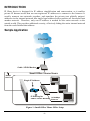
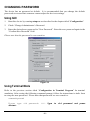
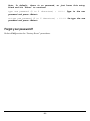
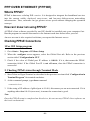
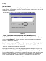
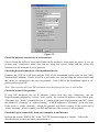
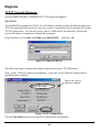
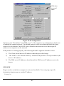
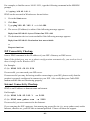
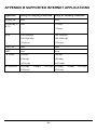
TW100-W1CA
IP Sharing for
Cable Modem/xDSL
User Manual
M73-APO07-080
FCC Certifications
This equipment has been tested and found to comply with the limits for a Class B digital
device, pursuant to Part 15 of the FCC Rules. These limits are designed to provide reasonable
protection against harmful interference in a residential installation. This equipment generates,
uses and can radiate radio frequency energy and, if not installed and used in accordance with
the instructions, may cause harmful interference to radio communications. However, there is
no guarantee that interference will not occur in a particular installation. If this equipment does
cause harmful interference to radio or television reception, which can be determined by
turning the equipment off and on, the user is encouraged to try to correct the interference by
one or more of the following measures:
?? Reorient or relocate the receiving antenna.
?? Increase the separation between the equipment and receiver.
?? Connect the equipment into an outlet on a circuit different from that to which the receiver
is connected.
?? Consult the dealer or an experienced radio/TV technician for help.
Shielded interface cables must be used in order to comply with emission limits.
You are cautioned that changes or modifications not expressly approved by the party
responsible for compliance could void your authority to operate the equipment.
This device complies with Part 15 of the FCC rules. Operation is subject to the following two
conditions: (1) This device may not cause harmful interference, and (2) This device must
accept any interference received, including interference that may cause undesired operation.
CE Mark Warning
This is a Class B product. In a domestic environment, this product may cause radio
interference, in which case the user may be required to take adequate measures.
All trademarks and brand names are the property of their respective proprietors.
Specifications are subject to change without prior notification.
TABLE OF CONTENT
INTROUCTION.......................................................................................................................................1
SAMPLE A PPLICATION ..................................................................................................................... 1
FEATURES............................................................................................................................................. 2
PARTS NAMES AND FUNCTIONS....................................................................................................... 2
SYSTEM REQUIREMENTS................................................................................................................... 4
FACTORY DEFAULT SETTINGS .......................................................................................................5
PASSWORD ............................................................................................................................................ 5
LOCAL AND GLOBAL PORT A DDRESSES.......................................................................................... 5
INFORMATION FROM ISP................................................................................................................... 5
CONFIGURATION.................................................................................................................................6
CONFIGURATION IN GUI.................................................................................................................... 6
How to start.....................................................................................................................................6
Management ...................................................................................................................................7
Local Port........................................................................................................................................9
Global Port ...................................................................................................................................10
Virtual Server ...............................................................................................................................11
Packet Filters ...............................................................................................................................12
CONFIGURATION IN TERMINAL PROGRAM M ODE...................................................................... 15
How to start HyperTerminal ......................................................................................................15
How to start Telnet ......................................................................................................................16
Starting Configured ....................................................................................................................17
TERMINAL COMMAND.....................................................................................................................18
PASSWD............................................................................................................................................... 18
SHOW ................................................................................................................................................... 19
SET ....................................................................................................................................................... 20
VSERV................................................................................................................................................... 21
RELEASE .............................................................................................................................................. 22
RENEW ................................................................................................................................................ 23
USER..................................................................................................................................................... 23
PING..................................................................................................................................................... 24
SESSION................................................................................................................................................ 24
FILTER................................................................................................................................................. 25
MAC address filter:......................................................................................................................25
IP address filter :..........................................................................................................................26
Port Filter......................................................................................................................................27
FIRMWARE UPGRADE......................................................................................................................28
SYSTEM REQUIREMENTS................................................................................................................. 28
BEFORE UPGRADE............................................................................................................................. 28
PERFORMING FIRMWARE UPGRADE .............................................................................................. 28
CHANGING PASSWORD..................................................................................................................31
FOR GUI.............................................................................................................................................. 31
FOR TERMINAL.................................................................................................................................. 31
FORGET YOUR PASSWORD?............................................................................................................. 32
PPP OVER ETHERNET (PPPOE)......................................................................................................33
W HAT IS PPPOE? .............................................................................................................................. 33
HOW CAN I KNOW I AM USING PPPOE?......................................................................................... 33
CHECKING PPPOE CONNECTIONS .................................................................................................. 33
1.For GUI Setup program...........................................................................................................33
2. Checking PPPoE status through terminal .........................................................................33
FAQ .........................................................................................................................................................34
FACTORY RESET ............................................................................................................................... 34
IP ADDRESS CONFLICT ...................................................................................................................... 35
M Y INT ERNET APPLICATION WON'T WORK ............................................................................... 35
CAN NOT ACCESS THE INTERNET .................................................................................................. 38
DIAGNOSIS .......................................................................................................................................... 40
TCP/IP Network Diagnosis........................................................................................................40
ISP Connectivity Checkup .........................................................................................................42
Internet Connectivity Checkup .................................................................................................42
GETTING TECHNICAL SUPPORT .................................................................................................... 43
APPENDIX A SPECIFICATIONS .....................................................................................................44
APPENDIX B SUPPORTED INTERNET APPLICATIONS .........................................................45
INTROUCTION
IP Share device is designed for IP address simplification and conservation, as it enables
private IP Internet works that use non-registered IP addresses to connect to the Internet. It
usually connects two networks together, and translates the private (not globally unique)
addresses in the internal network into single legal address before packets are forwarded onto
another network. Therefore, only one IP address is needed for the entire network to the
outside world. This provides additional security, effectively hiding the entire internal network
from the world behind that address.
Sample Application
Internet
ISP
Cable / XDSL Modem
Small Office / Home Users
10Mbps
Ethernet
Single IP Address
IP Sharing for
Cable / XDSL Modem
10/100Mbps
Ethernet
Figure 1: Small Office/ Home Office Setup
-1-
Features
?? Supports PPPoE.
?? Supports VPN.(PPTP pass through).
?? Explicit LED indication for Internet connection.
?? Supports Internet applications such as Web, ICQ, FTP, Telnet, E-Mail, News,
NetMeeting, PCAnyWhere, mIRC , CuSeeMe, AoE,…
?? Natural firewall keeps hackers out.
?? DHCP server allocates up to 128 client IP addresses.
?? DHCP client gets global IP address automatically.
?? 10/100Mbps dual speed auto-sensing for flexible network connectivity.
?? Virtual server.
?? Rich packet filters.
?? Static routing.
?? Supports Proxy-DNS.
?? Easy to setup by Windows GUI program and Telnet through network, or
HyperTerminal through Console.
?? Flash memory for firmware upgrade.
Parts Names and Functions
LED Indicators on the Front Panel
Ports on the Rear Panel
1 2 3 4 5 6 7
VDC IN
Console
Global
a
b
c
Figure 2: LED Indicators and Ports
-2-
Local
d
LED
Color
Indicator
? Power
Status
Glowing
Green
? Local Link Green
Dim
Flashing
Power On
Power Off
N/A.
Connected to a LAN
device
Disconnected from
any LAN device
Receiving/
Sending data
? Local
100/10
Green
100Mbps detected
10Mbps detected
N/A.
? Local
Full/Half
Green
Full duplex
Half duplex
N/A.
? Global
Link
Green
Connected to a
Cable/DSL Modem
Disconnected from
any Cable/DSL
modem
Receiving/
? (blank)
Green
Internet connected1
Internet disconnected N/A
? Error
Red
Components
malfunctioning
N/A.
Sending data
N/A.
Table 1: LED Indicators
Port Name
Functions
a
VDC IN
Connects the power adapter plug.
b
Console
Connects an RS-232 serial cable to your computer for
?? Configuring from terminal programs
?? Firmware upgrade.
1
c
Global
Connects to Ethernet port on Cable Modem or DSL Modem for Internet
Access.
d
Local
Connects to the Ethernet Hub/Switch on LAN.
Table 2: Connections Ports
For Cable modem connection, it means the device has received an IP address from the ISP.
For DSL modem connection, it means PPPoE connection has been established.
-3-
System Requirements
Your system must meet the following requirements to use the product’s Setup program. If you
are using a Unix or apple based system, telnet should be used to configure the product.
This product's GUI setup interface requires
1.
Windows 95, 98, ME, NT or 2000.
2.
IE4.01 or above well-installed.
Telnet and Terminal setup are operating system independent.
-4-
FACTORY DEFAULT SETTINGS
Password
The default setting for password has been left blank in the factory. Press Enter then you are
logged in for the first time. It is recommended that you set a password for security and
management purpose.
If you ever forget the password to log in, you can only reset the factory setting. Refer to the
next section titled “Factory Reset” for details.
Local and Global Port Addresses
The LAN parameters of the product are pre-set in the factory. The default values are shown
below.
Local Port
192.168.1.254
IP address
Subnet Mask
DHCP server function
255.255.255.0
Enabled
Global Port
DHCP client function is
enabled to automatically
get the Global port
configuration from ISP.
IP ADDRESSES FOR
128 IP addresses continuing from 192.168.1.1through
DISTRIBUTION TO PCS
192.168.1.128
Table 3: Local and Global Port Addresses
Information from ISP
If your IP address is provided dynamically by your ISP (Internet Service Provider), skip this
step. If you have a static address from your ISP, gather the information as illustrated in the
following table and keep it for reference.
IP address
ISP-assigning IP address
Ex. 203.66.81.201
Subnet mask
Ex. 255.255.255.0
Gateway
Ex. 203.66.81.254
DNS server #1
Ex. 203.66.81.251
DNS server #2
Ex. 203.66.81.252
Table 4: Assigned Addresses
-5-
CONFIGURATION
The product can be configured through the setup program (included in the package), through
a terminal emulation program, such as Windows HyperTerminal, or through Telnet. The
product can be set with a range of options to allow it to function in most any network
environment.
Configuration in GUI
How to start
1.
For the first time installation, in Windows, run setup.exe at the root directory.
Figure 3
2.
When the setup program is installed, go to Start? Programs ? IP Share Setup.
3.
When the opening screen appears, click Find to find the device you want to configure.
Figure 4
-6-
Figure 5
Select the device that you would like to setup and then click Configure.
Figure 6
The configure dialog box is categorized into several tabs as shown in the following.
Management
Figure 7
-7-
Firmware Version: Read-only.
Device/Computer Name: For you to enter a descriptive name for identification purpose. Some
Internet Service Providers (ISP) requires this information. The Maximum input for this field is
20 alphanumeric characters and it is case sensitive.
Domain Name 2:
For example: yourcompany.com. The maximum input for this field is 32 alphanumeric
characters and it is case insensitive.
PPPoE Enabled: If you are using PPPoE service, please check this box and enter the username
and password provided by your ISP.
PPPoE functions
?? Single Account Sharing: Multiple users can share one account.
?? Automatically connected to the Internet: Just launch your Internet program and the unit
will login and get on-line automatically.
?? Automatically disconnected from the Internet: This device will disconnect automatically
when it has been idle for a certain period of time.
Username: (for PPPoE)
?? Maximum input is 52 alphanumeric characters (case sensitive).
Password: (for PPPoE)
?? Maximum input is 36 alphanumeric characters (case sensitive).
Auto-disconnect…: This device can be configured to auto-disconnect when there is no
activity on the line for a certain period of time.
?? Default: 5 minutes. You can input any number from 0 to 65535.
?? To keep the line always connected, please set the number to 0.
Change Administrator Password: In this dialog box, you can set administrator’s password.
?? Maximum: 6 alphanumeric characters (case sensitive).
2
Your ISP may ask you to input a certain domain name. Domain name is also required for internal
network’s email and news functions.
-8-
TELNET management…: Checking this item lets you manage this device remotely from
outside of the network through Telnet.
?? Default: disabled.
Local Port
This screen contains settings for LAN interface attached to the local network.
Figure 8
IP Address
?? Default: 192.168.1.254
SubNetmask
?? Default: 255.255.255.0
?Do not distribute IP address to local computers 3
Checking this radio button to disable this IP Sharing device to distribute IP Addresses.
?Distribute IP addresses to local computers
Checking this radio button to enable this IP Sharing device to distribute IP Addresses. And
the following field will be activated for you to enter the starting IP Address:
3
If you check this selection, please specify unique static IP address for each of your local computers.
-9-
Continuous IP address pool starts at
The starting address of this local IP network address pool. The pool is a piece of continous IP
address segment.
Number of IP address in pool
?? Maximum: 128. Default: 128
Global Port
This screen contains settings for the Global interface toward Internet.
Figure 9
Adapter Address: Read-only. It is necessary for some ISP to identify this device by its MAC
address.
Obtain global port configuration automatically: If it is checked, the Global port IP address is
obtained through DHCP protocol after the device boots up. The address may vary each time
the device restarts.
Set static global port configuration: Check this item if your ISP provides you with a fixed IP
address.
IP address: Provided by your ISP.
- 10 -
SubNetmask4: Provided by our ISP.
Gateway/DNS server #1/DNS server #2: These values will be automatically provided once
you click “Obtain global port configuration automatically”. You can change the values if
necessary.
Virtual Server
Being a natural Internet firewall, this IP Sharing device protects your network from being
accessed by outside users. When there is application that requires outside users to access
internal servers (e.g. Web Server, Ftp Server, e-mail Server or News Server), this device can act
as a virtual server to public services. You can set up a local server with specific port number
which stands for the service (e.g. web(80), FTP(21), Telnet(23)). When this device receives an
incoming access request for this specific port, it will be forwarded to the corresponding
internal server.
Figure 10
Single Port/Port Range: For selecting between a specific port and a range of ports which you
want the Internet users to be able to access. The valid port number ranges from 0 to 65535.
Browse: If DHCP function is enabled, the distributed IP Addresses will appear on the screen.
You can select the desired IP address (for the specified port) and add it to the server list.
4
If you checked PPPoE in Management tab (see the Management section), the “Obtain global port
configuration automatically” and the “Set static global port configuration” fields are grayed out and
will not accept any input.
- 11 -
Figure 11
Port Type: please select the port type (TCP or UDP) for the port number that was entered
earlier.
Note: Maximum 12 Server Entries is allowed. Each port number can only be assigned to one
IP address.
Packet Filters
In the Packet Filters setup screen, you can block specific internal users from accessing the
Internet and you can also disable specific Internet services. You can set up the filters through
the following three types of filter. Each filter can be set to filter (drop) or forward (pass)
packets. You can input up to six filters in this device.
MAC Address Filter: filter according to local computer’s network adapter MAC address (also
known as the adapter card’s Physical Address).
IP Address Filter: Filter with computer’s IP address. You can filter a single IP, or a range of
the IP addresses.
?? LANIP: filtering IP address of a local computer.
?? WANIP: filtering IP address of a remote server (this remote server that connects to
Internet via this Internet Station).
Port Filter: Filter using the port number. You can set filter for a single port or a range of ports.
?? TCP port: filter according to the Connection-Based Application Service on the
remote server using the port number.
?? UDP port: filter according to the Connectionless Application Service on the remote
server using the port number.
- 12 -
Figure 12
Network Adapter Address Filter:
Filter according to local computer’s network adapter MAC address.
Figure 13
Network Adapter’s MAC address consists of 12 alphanumeric characters
(i.e. 00 ab 12 cd 34 ef) and it is normally printed on a sticker on the network adapter.
If you have Windows 95, 98, or 98Me, go to “Start”, select “Run”, and type in winipcfg. Select
the “network adapter” and you can find the Physical Address on the screen.
If you have NT or Win2000, open a DOS prompt window, type in ipconfig /all and then press
“Enter”. The MAC (Physical) Address along with adapter’s IP information will appear on the
screen.
IP Address Filter:
Allows IP address range setting.
Local IP: Filter according to the IP address of the local computer.
- 13 -
Remote IP: Filter using the IP address of a remote server (i.e. Web Server).
Figure 14
TCP/UDP Port Filter
TCP port: filter according to the Connection-Based Application Service on the remote server
using the port number.
UDP port: filter according to the Connectionless Application Service on the remote server
using the port number.
Figure 15
When you have finished setting the filters, the added filters will appear on the Filter List. To
remove a filter, click on the filter on the Filter List and click Delete.
After the configuration, click on Save to save the settings.
Figure 16
Please see examples on how to setup filters in Terminal Command section under vserv.
- 14 -
Configuration in Terminal Program Mode
You can use terminal emulation on your PC/workstation for the initial and future configuration
of your product. Windows HyperTerminal or other terminal emulation applications can be
used.
If you prefer, a telnet session can be opened directly. Telnet provides the same type of
terminal emulation. For security purposes, the product uses port 333 for telnet. All of the
following Terminal Mode Configuration menus are identical in the telnet session, with the
exception that any saved changes that result in the product rebooting, will require user to
open a new telnet session to reestablish a connection with the product. For more information
on telnet configuration, please see “How to Start Telnet” section below.
How to start HyperTerminal
1.
Power off the Internet Station.
2.
Connect an RS-232 cable from one Serial COM port on your PC to your product’s Serial
Console port
3.
In Windows, go to Start?Program?Accessories?Communications?HyperTerminal.
4.
When the HyperTerminal window appears, double-click Hypertrm to start a new session.
5.
Name the new connection and select an icon for this session.
6.
In the Connect To dialog box, select the COM port that you used to connect to the
Internet Station.
Figure 17: Connect To:
7.
When the dialog box in Figure 18 appears, select the Bits per second rate as 38400, and
Flow control at None. Click OK to complete the setting. See Figure 18.
- 15 -
Figure 18: COM 1 Properties
8.
Power up the product.
How to start Telnet
1.
The instructions below are for using this unit at its default settings (i.e. DHCP enabled,
Local Port IP address: 192.168.1.254, Subnet: 255.255.255.0).
2.
Go to Start?Run.
Figure 19
3.
Type “telnet 192.168.1.254 333” and click on OK. If the local port’s IP address was set
to something other than the factory default (“192.168.1.254”), enter that IP address.
- 16 -
333
Figure 20
Starting the Configuration
1.
Once the connection is made successfully either via HyperTerminal or Telnet, the
following information will appear,
Dual Ethernet IP Share for Cable/xDSL Modem, version X.XX
Administrator password:
2.
No password is required the first time you log in. Press <ENTER> to enter Configure
mode. The screen prompts you for the following command.
command>
3.
Type ? and hit “Enter” for a list of the commands.
Refer to the next section “Terminal Commands ” for detail description of terminal commands.
- 17 -
TERMINAL COMMAND
Type ? or help to list the main menu commands as below.
command>help
Dual Ethernet IP Share for Cable/xDSL Modem, version X.XX
=======================================================
Command
Description
------------------------------------------------------help
Show this message
session
List active internet sessions
show
Display active configuration
user
List active local IP address leases
filter
Set packet filters
passwd
Change administrator's password
ping <x.x.x.x>
Ping the specified host
release
Abandon the dynamic Global port configuration
renew
Refresh the dynamic Global port configuration
set
Configure device in batch
vserv
Set internal virtual server mapping
quit
Exit to login prompt
reboot
Restart device
======================================================
passwd
?? No password is required when logging in for the first time.
- 18 -
?? At command>, type in passwd and hit “Enter” to enter the password setup screen.
?? Password can be up to six characters long.
?? Password can contain letters, numbers, and spaces.
?? Password is case sensitive.
?? To set or change your password, key in up to six characters and hit “Enter”. You will be
prompted to reenter your password for verification. Return to the Start screen by typing
quit.
?? Test your new password to verify it has taken effect.
Example:
command>passwd
Please type old password :
type new password (0 to 6 characters) : ****
re-type new password (0 to 6 characters) : ****
show
Displays the current configuration. For first-time login, the current configuration is the factory
default settings. Refer to section titled “Factory Default Setting” for detail.
Example:
command>show
Wan Mac Address: AB CD 12 34 56 78
IP address of local port: [192.168.1.254]
SubNet mask of local port : [255.255.255.0]
Distribute IP addresses to local computers : [Yes]
Continuous IP address pool starts at : [192.168.1.1]
Number of IP address in pool : [128]
Enable PPPoE : [No]
- 19 -
Obtain global port configuration from ISP : [Yes]
.. under claiming
IP address of global port : [0.0.0.0]
SubNetmask of global port : [0.0.0.0]
Device name : [Untitled]
Domain name : [Domain]
Gateway : [0.0.0.0]
Primary DNS server : [0.0.0.0]
Secondary DNS server : [0.0.0.0]
set
After executing the set command, the current settings will appear on the screen one at a time.
Press Enter to accept the current value in the bracket or input new value and then press Enter
to change the value. Press <Esc> at any time to abort this command.
Example:
command>set
Press <ENTER> if you agree with the default value,
or <ESC> to escape.
IP address of local port [192.168.1.254] :
SubNetmask of local port [255.255.255.0] :
Distribute IP address to local computers ?(Yes/No) [Yes] :
Continuous IP address pool start at [192.168.1.1] :
Number of IP address in pool [128] :
Enable PPPoE ?(Yes/No) [No] :
Obtain global port configuration from ISP ?(Yes/No) [Yes] :
IP address of global port [0.0.0.0] :
- 20 -
SubNetmask of global port [0.0.0.0] :
Device name (0 to 20 characters) [Untitled] :
Domain name (0 to 36 characters) [Domain] :
Gateway [0.0.0.0] :
Primary DNS server [0.0.0.0] :
Secondary DNS server [0.0.0.0] :
New configuration will be:
IP address of local port : [192.168.1.254]
SubNetmask of local port : [255.255.255.0]
Distribute IP addresses to local computers : [Yes]
Continuous IP address pool starts at : [192.168.1.1]
Number of IP address in pool : [128]
Enable PPPoE : [No]
Obtain global port configuration from ISP : [Yes]
IP address of global port : [0.0.0.0]
SubNetmask of global port : [0.0.0.0]
Device name : [Untitled]
Domain name : [Domain]
Gateway : [0.0.0.0]
Primary DNS server : [0.0.0.0]
Secondary DNS server : [0.0.0.0]
Save and reboot ?(Yes/No) : [No]
vserv
Displays the internal virtual server mapping. You can set (including add, delete) the
applications’ names and the corresponding IP addresses of the local servers. “Natural
firewall” allows requests for Internet access from the Local network, but requests from the
- 21 -
Internet to the local network are blocked. Computers outside the Intranet are allowed to access
specific ports by using the vserv command.
There are four operation choices for vserv command: 1) Show, 2) Add, 3) Del, 0) Quit.
Example:
command>vserv
Set local virtual server mapping (maximum 12),
or <ESC> to escape
Operations => 1)Show 2)Add 3)Del 0)Quit : 2
Port number/application name : 80
? Add a virtual server
? it's a Web server
Type => 1)tcp 2)udp : 1
? select TCP port
Server IP address : 192.168.0.254
? IP address of the local Web server
Below are some Port Numbers for some Internet applications:
Nameport
Number
ftp
21
telnet
23
pop3
110
smtp
25
dns
53
www
80
news
119
gopher
70
Table 5
release
Gives up the obtained global port configuration. Executing this command disables the device,
unless the user executes the “renew” command as described below to retrieve configurations.
Example:
- 22 -
command>release
Give up the obtained global port configuration
Note: if you choose NOT to obtain the global port configuration from your ISP, this command won’t be
executed and the following message will appear.
command>release
Works only if 'Obtain global port configuration from ISP' is enabled
renew
You must renew the global port configuration after you have released it. Otherwise the device
is disabled. The ‘Show’ command enables you to see the configuration. The device will not
work until you renew the global port configurations.
Example:
command>renew
Update global port configuration
(You can type 'Show' command to view the new configuration)
Note: If you choose NOT to obtain the global port configuration from your ISP,
this command won’t be executed and the following message will appear.
command>renew
Works only if 'Obtain global port configuration
from ISP' is enabled
user
Displays the current active users (up to 128 users).
Example:
command>user
IP address
Node address
Remainder time
Host name
----------------+---------------+---------------+--------192.168.10.1
0080-C8F8-8A64
5:47:17
Allen
192.168.10.2
0080-C8F8-8A64
expired
Calvin
192.168.10.3
0080-C8F8-8A64
0:12:25
Edward
- 23 -
192.168.10.4
0080-C8F8-8A64
2:55:48
Victoria
192.168.10.5
0080-C8F8-8A64
expired
SNL
Total 5 user, 3 active lease.
Elapsed
0:01:03
Ping
Ping is a basic Internet program that lets you verify that a particular IP address exists and can
accept requests. At command> type in ping and then the IP address that you wish to detect. If
the screen shows “reply ok!” from that IP, the device can communicate with that IP address. If
the screen shows “no response!”, that IP address is unreachable.
Example:
command>ping 192.168.1.1
Reply OK.
command>ping 192.168.1.5
No response!
command>
session
List active Internet sessions through this device.
Example:
command>session
IP
T/U Flag
APType
client
Port
Port
client fake
IP
Port
remote
remote idle
---+-----+---------------+------+------+---------------+------+---+-----tcp
37
GERNERAL
192.168.10.27
1062
4133
210.66.41.132
110
0
tcp
7
GERNERAL
192.168.10.31
1032
4136
211.75.84.154
80
0
- 24 -
tcp
7
GERNERAL
192.168.10.31
1033
4138
211.75.84.154
80
0
tcp
7
GERNERAL
192.168.10.32
1729
4139
140.113.39.195
110
0
1063
4140
210.66.41.132
110
0
tcp
7
GERNERAL
192.168.10.27
udp
1
GERNERAL
192.168.10.31
1028
16385
168.95.192.1
udp
1
GERNERAL
192.168.10.32
1726
16386
168.95.1.1
udp
1
GERNERAL
192.168.10.32
Active >> TCP:5,UDP:3
1728
16387
168.95.192.1
53
20
53
5
53
5
(Maximum >> TCP:128,UDP:64)
filter
This device supports three types of filter. Each type of filter can be set to perform filter (drop)
or forward (pass) function. User can input up to six sets of filter in this device.
MAC address filter:
Example: Set the MAC address filter to prohibit the computer with network adapter address
0080C8123456 to access Internet.
command>filter
Set filter (maximum 6),or <ESC> to escape
Operations => 1)Show 2)Add 3)Del 0)Quit 2
add a new filter
Filter Type => 1)MAC 2)LAN IP 3)WAN IP 4)TCP 5)UDP 1 for MAC address
Action => 1)Forward 2)Filter 2 drop on match
MAC Address(12 HEX-digit) : 0080c8123456 the MAC address to be examined
Show Setting:
Operations => 1)Show 2)Add 3)Del 0)Quit 1
- 25 -
Item Type
Action
==== ====== =======
1.
MAC
Filter
From
To
================
================
0080C8123456
IP address filter:
Example 1: Set IP address filter to allow those local computers with IP address from
192.168.0.25 to 192.168.0.32 to access Internet.
Operations => 1)Show 2)Add 3)Del 0)Quit 2
Filter Type => 1)MAC 2)LAN IP 3)WAN IP 4)TCP 5)UDP 2 filter on IP
address of local computers.
Action => 1)Forward 2)Filter 1 pass on match
IP Address (x.x.x.x): 192.168.0.25-192.168.0.32 IP address range
Example 2: Inhibit all local users from accessing a specific web server on the Internet.
Operations => 1)Show 2)Add 3)Del 0)Quit 2
Filter Type => 1)MAC 2)LAN IP 3)WAN IP 4)TCP 5)UDP 3 filter on IP address of
remote server
Action => 1)Forward 2)Filter 2 drop on match
IP Address (x.x.x.x): 203.66.99.100 remote IP address
Show Settings:
Operations => 1)Show 2)Add 3)Del 0)Quit 1
Item
Type
Action
From
To
==== ====== ======= ================ ================
LAN IP
Forward
192.168.0.25
192.168.0.32
WAN IP
Filter
203.66.99.100
203.66.99.100
- 26 -
With the combination of the above two filter examples, the workstations with IP address 192.168.0.25,
192.168.0.26, 192.168.0.27, … and 192.168.0.32 can access the Internet via the Internet Router, but none of the
workstations can access the 203.66.99.100 Web Server (web site).
Port Filter
Example 1: Allow users to access Web service only.
Operations => 1)Show 2)Add 3)Del 0)Quit 2
Filter Type => 1)MAC 2)LAN IP 3)WAN IP 4)TCP 5)UDP 4 filter on server service
Action => 1)Forward 2)Filter 1 allow access
TCP port (xxx, or xxx-yyy): 80 port number for web service
Example 2: Inhibits all local computers from accessing some services.
Operations => 1)Show 2)Add 3)Del 0)Quit 2
Filter Type => 1)MAC 2)LAN IP 3)WAN IP 4)TCP 5)UDP 5
Action => 1)Forward 2)Filter 2
UDP port (xxx, or xxx-yyy):
are disabled.
20-25 services of FTP(20,21), TELNET(23), E-MAIL(25)
- 27 -
FIRMWARE UPGRADE
System Requirements
?? One free COM port on PC.
?? A pin-to-pin RS-232 cable. One end is 9 pin male connector, the other end is 9 or 25 pin
female connector depends on the COM port.
?? FWLOAD.EXE : This is an auxiliary program for firmware upload.
?? FIRMWARE.BIN : This is a firmware image file.
?? LOAD.EXE: This is the main program.
The above three files MUST reside in the same subdirectory.
For better disk access speed, it is recommended that you copy these two files to your hard
disk before uploading them to the product.
Before Upgrade
Close all other Windows programs and power off this device.
Performing Firmware Upgrade
1.
Connect the RS-232 cable from the Console port of the device to the PC’s COM port.
2.
Create a temporary folder in your system (e.g. NewFirmware.). Copy the downloaded
firmware file (should be a compressed file, e.g. FW3_20.EXE) to this temporary folder.
Decompress the file to any desired folder.
3.
Open the folder with the new firmware and double-click LOAD.EXE.
Figure 21
4.
Select the COM port that is connected to the device and click the Start button.
- 28 -
Figure 22
5.
When the following screen appears, power on the device.
Figure 23
6.
Expect to wait for a few seconds before the upload program detects the device. Once the
device is detected, the program will start uploading the firmware automatically. The
upload process takes a couple of minutes. After the upload is completed, this device will
automatically restart.
Note: DO NOT interrupt the firmware uploading process.
7.
When the upload finished, the screen should look like Figure 24 below.
Figure 24
If any error message appears, check the cable connection and make sure that you have
selected the correct COM port, then perform the upgrade again.
- 29 -
- 30 -
CHANGING PASSWORD
The device has no password at default. It is recommended that you change the default
passwords to ensure that someone cannot adjust the devices settings.
Using GUI
1.
Start this device by running setup.exe as described in the chapter titled “Configuration”.
2.
Check “Change Administrator’s Password.
3.
Enter the desired new password in “New Password”. Enter the new password again in the
“Confirm New Password” field.
Please note that the password is case sensitive.
Figure 25
Using Terminal Mode
Refer to the previous section titled “Configuration in Terminal Program” for terminal
emulation. After seeing the following command prompt, follow the instructions in italic fonts
to setup the new password. Please note that passwords are case sensitive.
command>passwd
Please type old password: **** Type in old password and press
<Enter>
- 31 -
Note: In default, there is no password, so just leave this entry
blank and hit “Enter” to continue.
type new password (0 to 6 characters) : ****** Type in the new
password and press <Enter>
re-type new password (0 to 6 characters) : ****** Re-type the new
password and press <Enter>
Forgot your password?
Refer to FAQ section for “Factory Reset” procedures.
- 32 -
PPP OVER ETHERNET (PPPOE)
What is PPPoE?
PPPoE is known as a dial-up DSL service. It is designed to integrate the broadband services
into the current widely deployed, easy-to-use, and low-cost dial-up-access networking
infrastructure. Thus, customer can get greater access speed without changing the operation
concept.
How can I know I am using PPPoE?
A PPPoE client software provided by our ISP should be installed onto your computer first.
Run the program to connect/disconnect to the Internet each time before/after you surf.
An user account is also required each time you request the Internet access.
Checking PPPoE Connections
1.For GUI Setup program
1. Go to Start? Programs ?IP Share Setup.
2. When the configure screen appears, select the Global Port tab. Refer to the previous
section titled “Configuration in GUI”.
3. Check if the value of Global port IP address is 0.0.0.0. If it is, that means the PPPoE
connection failed. If the Global Port IP is not all zeros, then the PPPoE connection is
successful.
2. Checking PPPoE status through Terminal Mode
1. Start Telnet or HyperTerminal as described in the previous section titled “Configuration in
Terminal Program” for terminal emulation.
2. At the command prompt, type show command.
command>show
3. If the string of IP address of global port is 0.0.0.0, this means you are not connected. If it is
anything other than 0.0.0.0 (non-zero), it means the connection is good.
Note:
Once the PPPoE setup is completed on this device, do not run any PPPoE client software on
the local workstations.
- 33 -
FAQ
Factory Reset
If for any reason, e.g. password being forgotten, you have to reset this device to factory
default settings. By performing the Factory Reset, the current settings will be lost and the
settings are reseted to default.
The fctory default values is detailed in the section Factory Default Settings.
Figure 26
“I can't find the product using the GUI Setup Software”
For the GUI Setup Software to find the device, it has to be accessed from a client. This means
that the computer you are trying to use to run the software must be setup as described in the
section Configuration in GUI. Also, the computer should be restarted to ensure that it is
receiving IP address from the device.
To verify that your computer’s TCP/IP protocol is setup properly, use the "winipcfg" utility in
Windows (95, 98, and 98Me). To run this, go to Start-->Run, type "winipcfg" in the Run box,
and then click “OK”. Make sure the Network Adapter Card is selected and then press the
"More Info" button on the bottom right hand corner.
Look at the box labeled DHCP Server, this should be the product's IP address (192.168.0.1 as
default). If it is not, or it is blank or reads 255.255.255.255 then you may have a cabling problem
(see above), or you may have another DHCP server on your network. In either case, please
follow the installation guide again, and ONLY connect the device, the client, and your modem
together. If you are on a network, it is recommended that you contact your IS manager for
further assistance with DHCP settings. Placing an IP Sharing Device that passes out IP
- 34 -
addresses on a LAN with an existing DHCP server may cause problems throughout a network.
It is recommended you disable other DHCP serves on the network if you plan on using this
product on the network.
IP address conflict
When you see the message box prompted for IP address conflict, this means two or more
workstations has the same IP address. If you have setup the device as a DHCP server, please
run the "winipcfg" utility to “release” all current configuration first, then “renew” the IP
information again. If the DHCP function is disabled and static IP addresses are assigned to
each workstation, please double check each workstation’s IP address for duplicate IP.
My Internet application won't work
To protect your computer from Hackers, the product uses “port blocking” technology. A port
is like a door into your computer. Each service on the Internet has an associated port. The
device protects your computer by closing certain ports, so that malicious programs can't
access your computer. However, if you are using an application that requires one of these
blocked ports, the application will not work. In this case, you will have to manually open these
ports to allow the application to work properly.
Some applications that may be affected are
Some Email Programs
Some Multi-Player Games
Some Internet Phone/Video Conferencing Applications
Als o, there are some applications, which require reverse connection over the Internet. In other
words, when you are connected to these applications, you have to open your ports for twoway connection.
The first thing you will need to do is determined what port (or ports) the application uses. The
fastest way to find this information is to go to the software maker's web site, go to the support
section, and look for information related to NAT, Proxy Server, or Firewall. This information
will typically list 1 to 3 ports that need to be opened for proper operation of the software. If
you can't find the necessary information, call the software maker and ask for what ports need
to be opened for the software to work through a firewall.
Once you have the necessary port information, follow the instructions below to setup the
“Virtual Server”.
A. Launch the Windows GUI Setup Software and press "Find". Once the GUI Setup Software
finds the product, press "Configure":
- 35 -
Figure 27
B. Choose the "Virtual Server" tab:
C. Enter one of the port numbers that your application requires and press "Browse".
Figure 28
D. Choose the computer that is using the application and press "Select".
Note: If you know the IP address of the computer that is using this application, you can
enter it in the “Local Server” and then click “add”.
- 36 -
Figure 29
E. Press Add. Repeat this process for each individual port you need to open.
Figure 30
- 37 -
F. Press Save. Wait 30 seconds for the device to reboot and then try the application again. It
may be necessary to restart your application or your computer for the application to recognize
the change.
Can not access the Internet
For Cable Modem users, find the workstation’s “Computer” name and then input this name
in the device’s “Device/Computer Name” field.
1. On the Workstation (95, 98, and 98Me), go to Start ?Control Panel ? Network, and select
Identification tab. Copy the Computer name as shown in the left figure below. For Win2000,
right click on “my computer”, select “properties”, click on “network identifications”, click on
“properties”, and then copy the computer name.
2. Run the GUI setup program, select the device, and click on “Configure” to go to the
Management tab.
3. Paste the name on to the field “Device/Computer Name” as shown in the right figure below.
Figure 31
For DSL PPPoE users, make sure you have entered the username along with your ISP
domain name. For example, [email protected], which is composed by username
(provided by your ISP) followed by your ISP’s domain.
- 38 -
Figure 32
Check the physical connectivity of local network.
Check if both the LEDs of Local and Global on the product’s front panel are green. If yes, go
to next step. Otherwise, make sure you are using the correct cables and the cables are
connected to the network devices properly.
Check the physical connectivity of the broadband device.
Examine the LED of LAN port and the LED of the broadband signal input on the Cable
Modem/xDSL Modem. If the LAN LED is off, make sure you are using the correct cables and
the cables are connected to the devices properly. If the LED of the broadband signal is off,
please contact your ISP.
Note: You can also call your ISP and make sure the Internet service is still online.
Check the status of this product.
If your ISP assigned you an IP address, please skip this step. Otherwise, use the
HyperTerminal program to “release” and “renew” the current IP address of the Global port.
After that, type “Show” command to see if “obtain global port configuration from ISP” shows
the address is “claiming” or “under claiming”. If the IP address is “claiming”, go to next step.
If the result is “under claiming”, reboot the product and check it again. If the result still is
“under claiming”, please contact your ISP and find out if the service is still available.
Check the logical connectivity from your computer to the Internet.
Refer to the section "PING.EXE" in the "TCP/IP Network diagnosis" chapter. Follow the
described steps to find out where the problem is.
- 39 -
Diagnosis
TCP/IP Network Diagnosis
Execute WINIPCFG.EXE or PING.EXE for TCP/IP network diagnosis.
WINIPCFG
The WINIPCFG program (for Win95, 98, and 98Me) is used to gather information about the
TCP/IP connections that are active on your system. It cannot be used to dynamically adjust
TCP/IP connections. You can also renew leases (if allowed by the network), and get the
current IP address assignments through this program.
From Windows, go to Start, click Run, enter WINIPCFG, and click OK.
Figure 33: Run WINIPCFG
The following figure displays the adapter address and current TCP/IP address.
Note: At the “Ethernet Adapter Information”, select the correct Ethernet adapter that is
installed in this computer.
Select the correct
Ethernet adapter.
Figure 34: IP Configuration
Click the More Info button to get detailed configuration information.
- 40 -
Click here
to reveal
more.
Figure 35: IP Configuration
On the top, the “Host Name” and “DNS server” of the computer are configured to call when it
is looking for a named resource. The default gateway is the server through which the client
connects to the Internet. The DHCP Server identifies the network server that assigns IP
addresses to computers on the network.
If the product is working properly, the following should be apparent from this screen:
1)
The Client should have an IP address within the prescribed range.
2)
The “DHCP” and “Default Gateway” should list the product’s local port address (the
device’s IP address).
3)
The DNS server IP addresses should match the DNS server IP addresses set in the
device.
PING.EXE
Ping is used to verify that a computer is active and available. Users can ping a specific
destination domain name or just the IP address.
Example:
- 41 -
For example, to find the server 168.95.192.1, type the following command at the MS-DOS
prompt:
C:\>ping 168.95.192.1.
PING can be executed in Windows as shown below:
1.
Go to the Start menu.
2.
Click Run.
3.
Type ping 168.95.192.1 and click OK.
4.
The server (IP address) is online if the following message appears.
Reply from 192.168.0.1: bytes=32 time=3ms TTL=100
5.
The destination device is not reachable if the following message appears.
Reply from 192.168.0.1: Destination host unreachable.
or
Request timed out.
ISP Connectivity Checkup
Issue a PING command to the IP address of your ISP’s Gateway or DNS server.
Note: If the global port was set to obtain configuration automatically, you need to check
these settings via the Windows GUI.
For Example:
C:\> PING 203.66.81.254
If successful, you can reach your ISP server.
If unsuccessful you may be having trouble connecting to your ISP, please verify that the
product is properly configured to connect to your ISP. Also verify that your Cable/DSL
modem and the line are functioning properly.
Internet Connectivity Checkup
PING to an IP address or domain name on Internet.
For Example:
C:\> PING 168.95.192.1
C:\> PING www.yahoo.com
–w 5000
–w 5000
If successful, you are connected to the Internet.
If you can ping the ISP’s gateway, but cannot ping a specific site (i.e. www.yahoo.com) on the
Internet, chances are, your ISP has an internal problem. Please call them for support.
- 42 -
Getting Technical Support
You can also contact us for technical support.
TRENDware
www.trendware.com
E-mail: [email protected]
Phone: 310-891-1100
- 43 -
APPENDIX A SPECIFICATIONS
Protocols
IP, NAT, ARP, ICMP, DHCP
Management/Setup
Locally, via direct serial cable connection through Console port
Options
Locally, via GUI for Windows 95/98/NT
Remotely via Telnet (needs to enabled this function via GUI )
Local Port
RJ-45, 10/100 Dual Speed Ethernet
Global Port RJ-45, 10Mb Ethernet to an external Cable/DSL Modem
Console Port
DB-9 female connector
LED Indicators
Power, Local Link, Local Speed 10/100, Local Full/Half Duplex,
Internet Link, Error
Input Power
5V DC @2.4A
Power Consumption
3.5 watt (max).
Agency and Regulatory: FCC part 15 Class B, VCCI, CE
Physical Dimension:
160 x 105.4 x 27 mm3 (L x W x H)
Weight:
218g
Operating Temperature: 0? to 50?
Operating Humidity:
0-90% non-condensing
- 44 -
APPENDIX B SUPPORTED INTERNET APPLICATIONS
Application
Settings for Outgoing Connection Setting for Incoming connection
ICQ98a,99b
None
None
Netmeeting 2.1 None
& 3.0
1503(tcp)
AOE
2300-2400(tcp)
2300-2400(tcp)
2300-2400(udp)
2300-2400(udp)
47624(tcp)
47624(tcp)
VDO Live
None
None
mIRC
None
None
Cu-Seeme
7648(tcp)
7648(tcp)
7648(udp)
7648(udp)
24032(udp)
24032(udp)
PCAnywhere
5632(udp),
65301(tcp)
1720(tcp)
22(udp),
5631(tcp), 5632(udp),
65301(tcp)
- 45 -
22(udp),
5631(tcp),