1
®
LabWindows /CVI
PID Control Toolkit
Reference Manual
October 1994 Edition
Part Number 320794A-01
© Copyright 1994 National Instruments Corporation.
All rights reserved.
National Instruments Corporate Headquarters
6504 Bridge Point Parkway
Austin, TX 78730-5039
(512) 794-0100
Technical support fax: (800) 328-2203
(512) 794-5678
Branch Offices:
Australia (03) 879 9422, Austria (0662) 435986, Belgium 02/757.00.20, Canada (Ontario) (519) 622-9310,
Canada (Québec) (514) 694-8521, Denmark 45 76 26 00, Finland (90) 527 2321, France (1) 48 14 24 24,
Germany 089/741 31 30, Italy 02/48301892, Japan (03) 3788-1921, Netherlands 03480-33466, Norway 32-848400,
Spain (91) 640 0085, Sweden 08-730 49 70, Switzerland 056/20 51 51, U.K. 0635 523545
Limited Warranty
The media on which you receive National Instruments software are warranted not to fail to execute programming
instructions, due to defects in materials and workmanship, for a period of 90 days from date of shipment, as
evidenced by receipts or other documentation. National Instruments will, at its option, repair or replace software
media that do not execute programming instructions if National Instruments receives notice of such defects during
the warranty period. National Instruments does not warrant that the operation of the software shall be uninterrupted
or error free.
A Return Material Authorization (RMA) number must be obtained from the factory and clearly marked on the
outside of the package before any equipment will be accepted for warranty work. National Instruments will pay the
shipping costs of returning to the owner parts which are covered by warranty.
National Instruments believes that the information in this manual is accurate. The document has been carefully
reviewed for technical accuracy. In the event that technical or typographical errors exist, National Instruments
reserves the right to make changes to subsequent editions of this document without prior notice to holders of this
edition. The reader should consult National Instruments if errors are suspected. In no event shall National
Instruments be liable for any damages arising out of or related to this document or the information contained in it.
EXCEPT AS SPECIFIED HEREIN , NATIONAL INSTRUMENTS MAKES NO WARRANTIES , EXPRESS OR IMPLIED ,
AND SPECIFICALLY DISCLAIMS ANY WARRANTY OF MERCHANTABILITY OR FITNESS FOR A PARTICULAR
PURPOSE . CUSTOMER ’S RIGHT TO RECOVER DAMAGES CAUSED BY FAULT OR NEGLIGENCE ON THE PART
OF NATIONAL INSTRUMENTS SHALL BE LIMITED TO THE AMOUNT THERETOFORE PAID BY THE CUSTOMER.
NATIONAL INSTRUMENTS WILL NOT BE LIABLE FOR DAMAGES RESULTING FROM LOSS OF DATA , PROFITS ,
USE OF PRODUCTS , OR INCIDENTAL OR CONSEQUENTIAL DAMAGES , EVEN IF ADVISED OF THE POSSIBILITY
THEREOF . This limitation of the liability of National Instruments will apply regardless of the form of action,
whether in contract or tort, including negligence. Any action against National Instruments must be brought within
one year after the cause of action accrues. National Instruments shall not be liable for any delay in performance due
to causes beyond its reasonable control. The warranty provided herein does not cover damages, defects,
malfunctions, or service failures caused by owner’s failure to follow the National Instruments installation, operation,
or maintenance instructions; owner’s modification of the product; owner’s abuse, misuse, or negligent acts; and
power failure or surges, fire, flood, accident, actions of third parties, or other events outside reasonable control.
Copyright
Under the copyright laws, this publication may not be reproduced or transmitted in any form, electronic or
mechanical, including photocopying, recording, storing in an information retrieval system, or translating, in whole
or in part, without the prior written consent of National Instruments Corporation.
Trademarks
NI-DAQ ® is a trademark of National Instruments Corporation.
Product and company names listed are trademarks or trade names of their respective companies.
WARNING REGARDING MEDICAL AND CLINICAL USE
OF NATIONAL INSTRUMENTS PRODUCTS
National Instruments products are not designed with components and testing intended to ensure a level of reliability
suitable for use in treatment and diagnosis of humans. Applications of National Instruments products involving
medical or clinical treatment can create a potential for accidental injury caused by product failure, or by errors on
the part of the user or application designer. Any use or application of National Instruments products for or involving
medical or clinical treatment must be performed by properly trained and qualified medical personnel, and all
traditional medical safeguards, equipment, and procedures that are appropriate in the particular situation to prevent
serious injury or death should always continue to be used when National Instruments products are being used.
National Instruments products are NOT intended to be a substitute for any form of established process, procedure, or
equipment used to monitor or safeguard human health and safety in medical or clinical treatment.
Contents
About This Manual ............................................................................................................vii
Organization of This Manual .........................................................................................vii
Conventions Used in This Manual.................................................................................vii
Related Documents ........................................................................................................viii
Customer Communication .............................................................................................ix
Chapter 1
PID Control Toolkit Overview .......................................................................................1-1
Installing the LabWindows/CVI PID Control Toolkit...................................................1-1
Windows ............................................................................................................1-1
SPARCstation ....................................................................................................1-2
Product Overview ..........................................................................................................1-2
The PID Control Toolkit Function Panels .....................................................................1-3
Designing a Control Strategy.........................................................................................1-4
Scaling I/O Values .............................................................................................1-5
Setting Up Timing..............................................................................................1-6
Tuning Your Controller .....................................................................................1-6
Closed-Loop (Ultimate Gain) Tuning Procedure...................................1-6
Open-Loop (Step Test) Tuning Procedure.............................................1-7
General Description of the PID Functions.....................................................................1-9
Particulars of the PID Algorithm .......................................................................1-10
Example Programs .........................................................................................................1-12
PIDDEMO ......................................................................................................... 1-12
PIDDAQ.............................................................................................................1-13
LDLGDEMO .....................................................................................................1-13
RAMPDEMO.....................................................................................................1-14
Chapter 2
PID Control Function Reference ...................................................................................2-1
pid_config ......................................................................................................................2-1
pid_cycle ........................................................................................................................2-2
pid_e2_cycle ..................................................................................................................2-3
pid_ext_cycle .................................................................................................................2-4
pid_ld_lg_cycle..............................................................................................................2-5
pid_ld_lg_tune ...............................................................................................................2-5
pid_manualset ................................................................................................................2-6
pid_mode........................................................................................................................2-6
pid_ramp ........................................................................................................................2-7
pid_setpoint....................................................................................................................2-8
pid_tune..........................................................................................................................2-8
© National Instruments Corporation
v
LabWindows/CVI PID Control Toolkit
Contents
Appendix A
Customer Communication ..................................................................................Appendix-1
Glossary ......................................................................................................................Glossary-1
Figures
Figure
Figure
Figure
Figure
Figure
Figure
1-1.
1-2.
1-3.
1-4.
1-5.
1-6.
Control Flowchart .............................................................................................1-4
Output and Process Variable Strip Chart ...........................................................1-8
Front Panel of the Tank Level PID Demo ......................................................... 1-12
Front Panel of the Resistor-Capacitor Network Example..................................1-13
Front Panel of the Lead-Lag Demo....................................................................1-14
Front Panel of the Ramp Demo ......................................................................... 1-14
Tables
Table
Table
Table
Table
1-1.
1-2.
1-3.
1-4.
The PID Toolkit Function Tree..........................................................................1-3
Closed-Loop Quarter-Decay Ratio Values ........................................................1-7
Open-Loop Quarter-Decay Ratio Values...........................................................1-9
PID Algorithm Variables ...................................................................................1-10
LabWindows/CVI PID Control Toolkit
vi
© National Instruments Corporation
About This Manual
The LabWindows/CVI PID Control Toolkit Reference Manual is a reference guide to the
LabWindows/CVI PID control instrument driver and examples. It assumes you have a basic
understanding of process control strategies and algorithms. If you are not familiar with process
control terminology, methods, and standards, see the Related Documents section in About This
Manual for other sources of information.
Organization of This Manual
This manual is organized as follows:
•
This chapter contains the following information about the Proportional-Integral-Derivative
(PID) Control toolkit.
–
how to install the PID Control toolkit on your computer
–
product overview
–
how to design a control strategy
–
general information about the PID Control functions
–
introduction to the example programs
•
Chapter 2, PID Control Function Reference, contains a brief explanation of each of the
functions in the LabWindows/CVI PID Control Toolkit.
•
Appendix A, Customer Communication, contains forms you can use to request help from
National Instruments and to comment on our products and manuals.
•
The Glossary contains an alphabetical list and description of terms used in this manual,
including abbreviations, acronyms, metric prefixes, mnemonics, and symbols.
Conventions Used in This Manual
The following conventions are used in this manual:
bold
Bold text denotes parameters, or the introduction of menu or function
panel items.
italic
Italic text denotes emphasis, a cross reference, or an introduction to a key
concept.
monospace
Text in this font denotes text or characters that you should literally input
from the keyboard, sections of code, programming examples, and syntax
examples. This font is also used for the proper names of disk drives,
paths, directories, programs, subprograms, subroutines, device names,
© National Instruments Corporation
vii
LabWindows/CVI PID Control Toolkit
About This Manual
functions, variables, filenames, and extensions, and for statements and
comments taken from program code.
italic
monospace
Italic text in this font denotes that you must supply the appropriate
word or value in the place of these terms, for example, filename .
<Ctrl>
Key names in the text match the names on the computer keyboard, and
they are surrounded by angled brackets. For example, the Control key
appears in the text as <Ctrl>.
-
A hyphen between two or more key names denotes that you should
simultaneously press the named keys, for example, <Ctrl-Alt-Del>.
Abbreviations, acronyms, metric prefixes, mnemonics, symbols, and terms are listed in the
Glossary.
Related Documents
The following documentation available from National Instruments contains information that you
may find helpful as you read this manual.
•
Getting Started with LabWindows/CVI
•
LabWindows/CVI User Manual
•
LabWindows/CVI Standard Libraries Reference Manual
•
LabWindows/CVI Instrument Library Developer's Guide
•
NI-DAQ Software Reference Manual for DOS/LabWindows
•
NI-DAQ Function Reference Manual
The following documentation also contains information that you may find helpful as you read
this manual:
•
Corripio, A.B. Tuning of Industrial Control Systems. Raleigh, North Carolina: ISA, 1990.
ISBN 1-55617-233-8.
•
Shinskey, F.G. Process Control Systems. New York: McGraw-Hill, 1988.
ISBN 0-07-056903-7.
The Instrument Society of America (ISA), the organization that sets standards for process control
instrumentation in the United States, offers a catalog of books, journals, and training materials to
teach you the basics of process control programming. One course in particular is very helpful—
Single and Multiloop Control Strategies, course number T510. For information, contact the ISA
at its Raleigh, North Carolina, headquarters at (919) 549-8411.
LabWindows/CVI PID Control Toolkit
viii
© National Instruments Corporation
About This Manual
Tuning of Industrial Control Systems is an ISA Independent Learning Module book. It is
organized as a self-study course covering measurement and control techniques, selection of
controllers, and advanced control techniques. Tuning procedures are detailed and yet easily
understandable. Process Control Systems is an outstanding general text covering the application,
design, and tuning of all common control strategies. It contains all of the basic algorithms used
in the LabWindows/CVI PID Control Toolkit process control functions.
Customer Communication
National Instruments wants to receive your comments on our products and manuals. We are
interested in the applications you develop with our products, and we want to help if you have
problems with them. To make it easy for you to contact us, this manual contains comment and
configuration forms for you to complete. These forms are in Appendix A, Customer
Communication, at the end of this manual.
© National Instruments Corporation
ix
LabWindows/CVI PID Control Toolkit
Chapter 1
PID Control Toolkit Overview
This chapter contains the following information about the Proportional-Integral-Derivative (PID)
Control toolkit.
•
how to install the PID Control toolkit on your computer
•
product overview
•
how to design a control strategy
•
general information about the PID Control functions
•
introduction to the example programs
Installing the LabWindows/CVI PID Control Toolkit
The following sections contain instructions for installing the PID Control toolkit on the Windows
and Sun SPARCstation platforms.
The LabWindows/CVI PID Control Toolkit comes in compressed form on a floppy disk.
Installing the PID Control toolkit requires approximately 1.2 MB.
Some virus detection programs may interfere with the installer program. Check the distribution
disks for viruses before you begin installation. Then turn off the automatic virus checker and run
the installer. After installation it is good practice to check your hard disk for viruses again, then
turn on the virus checker.
Windows
You can install the PID Control toolkit from the Windows File Manager or with the Run...
command from the File menu of the Program Manager.
Insert the PID Control Toolkit disk into the 3.5-inch disk drive and run the SETUP.EXE
program using one of the following methods.
•
Under Windows, launch the File Manager. Click on the drive icon that contains the
installation disk. Find SETUP.EXE in the list of files on that disk and double-click on it.
•
Under Windows, select Run... from the File menu of the Program Manager. A dialog box
appears. Type X:\SETUP (where X is the proper drive designation).
After you choose an installation option, follow the instructions that appear on the screen.
© National Instruments Corporation
1-1
LabWindows/CVI PID Control Toolkit
PID Control Toolkit Overview
Chapter 1
SPARCstation
You can install the PID Control toolkit as shown in the following steps. You do not need root
privileges to install the PID Control toolkit, but you must be able to write to the
LabWindows/CVI directory where you will install the PID Control toolkit.
1. Insert the first disk into the 3.5-inch disk drive.
2. Type the following UNIX command: tar xvf /dev/rfd0a INSTALL
3. Run the installation program by typing the following command: ./INSTALL
4. Follow the instructions on screen.
Product Overview
The PID Control toolkit adds sophisticated control algorithms to LabWindows/CVI. All
algorithms are implemented in LabWindows/CVI instrument functions, so you have the source
code to modify for your own application. The toolkit includes programming functions for PID
control loops. It uses conventional, external reset feedback, and error squared PID algorithms.
To obtain the source code for the toolkit, perform the following steps.
1. Select Load… from the Instruments menu. The Load Instrument dialog box appears.
2. Select pid.fp in the list box within the dialog box.
3. Select Edit from the Instruments menu. The Edit Instrument dialog box appears.
4. Highlight PID Control and click on the Attach and Edit Source button.
LabWindows/CVI PID Control Toolkit
1-2
© National Instruments Corporation
Chapter 1
PID Control Toolkit Overview
The PID Control Toolkit Function Panels
The PID Control Toolkit function panels are grouped in a tree structure according to the types of
operations performed. The PID Control Toolkit function tree is shown in Table 1-1.
Table 1-1. The PID Control Toolkit Function Tree
PID Control
Configure
Setpoint
Tune
Mode
Manual Set
Cycle
Conventional Cycle
Error Squared Cycle
External Fdbk Cycle
Lead Lag
Lead Lag Tune
Lead Lag Cycle
Ramp
pid_config
pid_setpoint
pid_tune
pid_mode
pid_manualset
pid_cycle
pid_e2_cycle
pid_ext_cycle
pid_ld_lg_tune
pid_ld_lg_cycle
pid_ramp
PID Control is a set of functions for implementing PID control in LabWindows/CVI.
•
pid_config sets up initial tuning parameters, mode, and derivative gain limit.
•
pid_setpoint sends a new setpoint to a control loop.
•
pid_tune specifies new tuning parameters (proportional band, reset time, rate time).
•
pid_mode selects the operating mode (auto or manual) for a control loop.
•
pid_manualset adjusts the output value directly (applies to manual mode only). The
setting is a relative value, in other words, an offset from the output at the time the controller
was placed in manual mode.
•
Cycle represents the class of PID cycle functions that are called repeatedly to perform the
PID computations and create a new output value, given the value of the process variable.
–
pid_cycle calculates an analog output value based on the current value of the process
variable (PV) and setpoint using a PID algorithm.
–
pid_e2_cycle calculates an analog output value with a nonlinear proportional-error
response based on the current value of PV and setpoint using a PID algorithm.
© National Instruments Corporation
1-3
LabWindows/CVI PID Control Toolkit
PID Control Toolkit Overview
–
•
•
Chapter 1
pid_ext_cycle calculates an analog output value with a nonlinear proportional-error
response based on the current value of PV, setpoint, and reset feedback using a PID
algorithm.
Lead Lag represents the class of PID cycle functions for calculating the dynamic
compensator in feedforward control schemes.
–
pid_ld_lg_tune specifies new Lead-Lag tuning parameters (gain, lag time, and lead
time).
–
pid_ld_lg_cycle calculates the dynamic compensator in feedforward control
schemes.
pid_ramp generates a setpoint ramp.
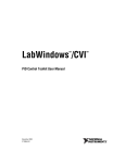
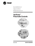
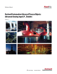
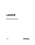
Designing a Control Strategy
The first step in designing a control strategy is to sketch a flowchart of your process showing
control elements (for example, valves) and measurements. Add feedback and any required
computations, as textbooks on the subject of process control recommend. Then translate the
diagram into a C program using the PID Control functions. An example of a diagram is shown
in Figure 1-1, followed by the corresponding code fragment.
Cascade/Feedforward Surge Tank Level Control
FT
1
SP
LC
∑
SURGE
TANK
SP
LC
LT
1
FT
2
Figure 1-1. Control Flowchart
After configuring both control loops using pid_config, the following loop would be used to
control the tank level process.
LabWindows/CVI PID Control Toolkit
1-4
© National Instruments Corporation
Chapter 1
PID Control Toolkit Overview
while (running)
{
/* Hardware specific function to read the in-flow from FT1 */
inflow = read_FT1();
/* The in-flow serves as the setpoint for the first PID */
pid_setpoint (LOOP1, inflow);
/* Hardware specific function to read the tank level from LT1 */
level = read_LT1();
/* The tank level is the process variable for the first PID */
mv = pid_cycle (LOOP1, level);
/* The manipulated variable from the first PID combines with
the input flow to form the setpoint for the second PID
*/
pid_setpoint (LOOP2, inflow + mv);
/* Hardware specific function to read the output flow from FT2 */
outflow = read_FT2();
/* Determine the new valve position using the output flow
read from FT2 as the process variable for the second PID */
valve_position = pid_cycle (LOOP2, outflow);
/* Hardware specific function to update the valve position */
update_valve(valve_position);
}
You handle the inputs and outputs through data acquisition boards, GPIB instruments, or serial
I/O ports. All functions in this package use a consistent amplitude scaling of zero to 100 percent.
You can also adjust polling rates in real time. These rates are limited only by the hardware you
use and the graphic complexity of your user interface.
Scaling I/O Values
All the functions in this package use inputs and outputs scaled as percentages. This makes
control calculations simpler and return values more understandable. You must be sure to
properly scale your physical measurements and outputs, however.
For example, you can use a National Instruments data acquisition board to acquire a 4 to 20 mA
signal with a 250 Ω sampling resistor, giving a voltage of 1 to 5 V. To convert voltage data to
percentages, you need to subtract 1.0 V and then multiply by 25 to scale the signal to a
percentage.
When calculating controller gain (proportional band), you can easily scale your physical
measurement to percentage of span. The span is defined as the difference between the maximum
and minimum measurements.
For example, consider a temperature transmitter scaled from -100 to 1,200 C. Its span is
1,300 C. A controller proportional band of 10 percent means an input error of 130 C relative to
the setpoint is just enough to drive the controller output to saturation.
© National Instruments Corporation
1-5
LabWindows/CVI PID Control Toolkit
PID Control Toolkit Overview
Chapter 1
Setting Up Timing
There are two ways to supply timing information to PID routines: through the cycle_time
parameter or through a built-in time keeper. If cycle_time is less than or equal to zero, then
each time the function is called, cycle_time measures the time since the last call and uses
that time in its calculations. For most situations the given function is called from within a loop
which uses Timer or some similar function that passes cycle_time as -1. This results in
fairly regular timing, and the internal time keeper compensates for variations that occur. There is
one limitation to this scheme. Timer resolution is limited to 55 ms under Windows. On Sun
workstations, timer resolution is 10 ms for machines operating under Solaris 1 and 1 ms for
machines operation under Solaris 2. For this reason, the functions should not be called faster than
5 or 10 Hz when cycle time is less than or equal to zero.
If cycle_time is a positive value (in seconds), the function uses this value in the calculations,
regardless of the elapsed time. This method works for any interval and should be used for fast
loops such as when the acquisition hardware is already doing the timing.
According to control theory, a sampled control system must run about 10 times faster than the
fastest time constant in the plant under control. For instance, a temperature control loop is
probably quite slow—a time constant of 60 s is common in a small system. In this case, a loop
iteration time of about 6 s is sufficient. Faster cycling does not improve performance. The selfstudy course Tuning of Industrial Control Systems, mentioned in About This Manual, contains
more information on this topic.
Tuning Your Controller
The two controller tuning procedures described in the following sections derive from the work of
Ziegler and Nichols, who developed Quarter-Decay Ratio tuning techniques from a combination
of theory and empirical observations. Experiment with these techniques in your process or using
one of the example programs included with this instrument driver. Depending on the process,
one tuning method may be easier or more accurate than the other. There are also techniques you
can use with online controllers that cannot withstand the gross upsets described here. The ISA
documents cited in the Related Documentation section of About This Manual give more
information on this topic.
To perform these tests with LabWindows/CVI, set up your control strategy with the process
variable (PV), setpoint, and output displayed on a large strip chart with the axes showing
percentage versus time. Then perturb the loop as described in the Closed-Loop (Ultimate Gain)
Tuning Procedure and Open-Loop (Step Test) Tuning Procedure sections of this chapter, and
determine the response from the graph.
Closed-Loop (Ultimate Gain) Tuning Procedure
The closed-loop (ultimate gain) tuning procedure is very accurate, but requires that you put your
process in steady-state oscillation. You must observe the process variable on a strip chart. To
perform the closed-loop tuning procedure, complete the following steps.
LabWindows/CVI PID Control Toolkit
1-6
© National Instruments Corporation
Chapter 1
PID Control Toolkit Overview
1. Use pid_time to set both the rate and reset on your PID controller to zero.
2. With the controller in automatic mode, carefully reduce the proportional band (PropBand) in
small steps using pid_tune. Disturb the loop after each step by making a small change in
setpoint using pid_setpoint. The process variable should start oscillating as you reduce
the PropBand. Keep making changes until the oscillation is perfectly sustained, neither
growing nor decaying over time.
3. Record the controller proportional band as PBu in percent.
4. Record the period of the oscillation as T u in minutes.
5. Multiply the measured values by the factors shown in Table 1-2, and enter the new tuning
parameters into your controller. This table gives the proper values for a quarter-decay ratio.
If you want less overshoot, increase the PB, which has the same effect as reducing the gain.
Table 1-2. Closed-Loop Quarter-Decay Ratio Values
Controller
PB (percent)
reset (minutes)
rate (minutes)
P
2.00 PB u
—
—
PI
2.22 PB u
0.83 Tu
—
PID
1.67 PB u
0.50 Tu
0.125 Tu
The self-study course Tuning of Industrial Control Systems, mentioned in About This Manual,
contains more information on this topic.
Open-Loop (Step Test) Tuning Procedure
The open-loop (step test) tuning procedure is based on the assumption that you can model any
process as a first-order lag and a pure dead time. This method requires more analysis than the
closed-loop tuning procedure, but your process does not need to reach sustained oscillation.
Therefore, the open-loop tuning procedure is probably quicker and less hazardous for many
processes. You must display the output and the process variable (PV) on a strip chart that shows
time on the X axis.
To perform the open-loop tuning procedure, complete the following four steps.
1. Put the controller in manual mode using pid_config, set the output to a nominal operating
value using pid_manualset, and let PV settle completely. Record the PV and output
values.
2. Make a step change in the output. Record the new output value.
© National Instruments Corporation
1-7
LabWindows/CVI PID Control Toolkit
PID Control Toolkit Overview
Chapter 1
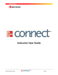
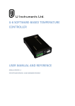
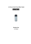
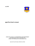
3. Wait for PV to settle. From the chart, determine the values as derived from the sample
displayed in Figure 1-2. The values are as follows.
•
Td — Dead time in minutes
•
T — Time constant in minutes
•
K — Process gain =
percent change in output
percent change in PV
Max
63.2% (Max-Min)
PV
Min
Output
Td
T
Figure 1-2. Output and Process Variable Strip Chart
To calculate the percent change in PV, you need to know the transmitter span. See the
Scaling I/O Values section of this chapter for information on calculating the transmitter span.
For example, the span of a temperature transmitter scaled from -100 to 900 C is 1,000 C. If
the starting temperature is 200 and the final value is 400, the percent change is as follows.
50% - 30% = 20%
If the controller output was stepped with increments of 10 percent, the process gain is as
follows.
K=
10%
20%
= 0.5
4. Multiply the measured values by the factors shown in Table 1-3, and enter the new tuning
parameters into your controller. This table gives the proper values for a quarter-decay ratio.
If you want less overshoot, increase the PB, which has the same effect as reducing the gain.
LabWindows/CVI PID Control Toolkit
1-8
© National Instruments Corporation
Chapter 1
PID Control Toolkit Overview
Table 1-3. Open-Loop Quarter-Decay Ratio Values
Controller
PB (percent)
reset (minutes)
rate (minutes)
KT d
T
KT d
110 T
KT
80 T d
—
—
3.33 Td
—
2.00 Td
0.50 Td
P
PI
PID
100
The self-study course Tuning of Industrial Control Systems, mentioned in About This Manual,
contains more information on this topic.
General Description of the PID Functions
The PID functions use an interacting positional PID algorithm. Rate action is affected by the
process variable only. The functions include anti-reset windup and bumpless auto/manual
transfer. The book Process Control Systems, mentioned in About This Manual, contains more
information on this topic.
The functions express setpoint, process variable, and output in percent. Reverse action (also
called increase-decrease) is the default controller mode, in which the output decreases if process
variable is greater than setpoint. proportional band is a percentage value. The equation for
controller gain is therefore as follows.
G=
100
PB
The functions measure reset and rate in minutes.
Switching to manual mode freezes the output at the current value. In manual mode, you can then
increase or decrease the output by changing the manual input. All transitions, from auto to
manual and from manual to auto, are bumpless, as a result of a bias tracking technique. The book
Process Control Systems, mentioned in About This Manual, contains more information on this
topic.
You should call these functions from inside a while loop with a fixed iteration time. The
LabWindows/CVI PID Control toolkit can accommodate a fixed number of control loops
running at the same time. Each function in the library takes a control loop selector as a
parameter. Currently the number of loops is set at 5 (loop selectors 0-4). This number is
arbitrary, and you can change it by modifying the constant NLOOPS and resaving the instrument
driver.
Two modifications of the conventional PID cycle are available in the PID Control toolkit. The
Error Squared Cycle performs conventional PID, except that its proportional error response is
nonlinear. For some processes, increasing the controller gain as the error magnitude increases
improves response time and damping. The book Process Control Systems, mentioned in About
© National Instruments Corporation
1-9
LabWindows/CVI PID Control Toolkit
PID Control Toolkit Overview
Chapter 1
This Manual, contains more information on this topic. The PID External Reset Feedback Cycle
derives the input for reset (integral) calculation from an external source. Normally, this input is
the previous controller output value. More complex control schemes, such as a selector (limit)
control in which the offline controller tends to wind up, need this connection.
Particulars of the PID Algorithm
Table 1-4 shows the variables used by the PID algorithms that the process control functions
implement.
Table 1-4. PID Algorithm Variables
Variable
Description
P
Proportional band in percent (a negative value indicates
forward action)
I
D
Kd
Integral (reset) in minutes per reset
Derivative (rate) in minutes per repeat
Derivative gain limit (always > 1; values of 10 to 20 are
normal)
PV
SP
m
mh
Process variable in percent
Setpoint in percent
Manipulated variable (output of controller) in percent
High limit for manipulated variable in percent
ml
M
e
Low limit for manipulated variable in percent
b
y
f
L
∆t
Bias in percent
Output of derivative filter in percent
Feedback signal for the integral term in percent
Linearity parameter for the error-squared controller
Cycle time of the algorithm in minutes
Manipulated variable in manual mode in percent
Error (difference between setpoint and process variable) in
percent
The book Process Control Systems, mentioned in About This Manual, contains more information
on this topic.
LabWindows/CVI PID Control Toolkit
1-10
© National Instruments Corporation
Chapter 1
PID Control Toolkit Overview
The PID Control toolkit implements the equations in source code, so you can modify them if
necessary. The functions execute the equations in the following order.
1. Derivative filter:
( PV − y)
y = y + ∆t
D
∆t +
Kd
2. Proportional algorithm:
100
SP − PV − K d ( PV − y ))
m = b+
P (
3. Output limiting:
if m > m h then m = mh
if m < m l then m = ml
4. Integral action:
f−b
b = b + ∆t
∆t + I
For the PID Conventional Cycle, f is equal to m, the manipulated variable. For the PID External
Reset Feedback function, you supply f through a control on the user interface.
The PID Error Squared Cycle modifies step two to produce a nonlinear gain term in which the
gain increases with the magnitude of the error:
abs( e )
100
L + (1 − L )
m = b + e
P
100
where e = SP − PV − K d ( PV − y ) as in the normal proportional algorithms. If L is 1, the controller is
linear. A value of 0.1 makes the minimum gain of the controller
10
.
P
To implement bumpless transfer from manual to automatic mode, a bias tracking technique
eliminates proportional kick at transfer time. During manual mode, the function uses the
following formula to calculate the bias.
100
e
b = m−
P
In effect, the automatic mode output (as a result of this bias shift) is always equal to the manual
output. This method is effective for modest values of deviation, beyond which a proportional
© National Instruments Corporation
1-11
LabWindows/CVI PID Control Toolkit
PID Control Toolkit Overview
Chapter 1
kick occurs because the bias never winds up infinitely. At some point, the manually induced
deviation can no longer be tracked by the limited bias. The alternative is to let the bias wind up,
which can cause serious problems in normal operation.
Example Programs
Included with the LabWindows/CVI PID Control Toolkit are four example programs, PIDDEMO,
PIDDAQ, LDLGDEMO, and RAMPDEMO. You can run these examples from the
LabWindows/CVI environment.
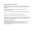
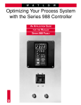
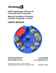
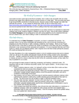
PIDDEMO
PIDDEMO is a simulated water tank level control. It requires no plug-in boards or external
hardware. It uses a single conventional PID loop to control the tank level. The PID tuning
parameters, as well as the water tank simulator characteristics, are available on the user interface
panel for modification at run time.
Figure 1-3. Front Panel of the Tank Level PID Demo
LabWindows/CVI PID Control Toolkit
1-12
© National Instruments Corporation
Chapter 1
PID Control Toolkit Overview
This example uses an integrating process with added noise, valve dead band, lag, and dead time.
This simple example does not account for time; thus, it does not correct itself for loop cycle time.
This example also demonstrates switching from automatic to manual mode.
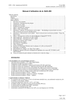
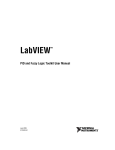
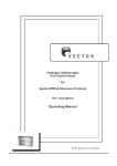
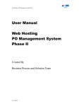
PIDDAQ
PIDDAQ is a real controller for a resistor-capacitor network. It requires a National Instruments
I/O board and the resistor-capacitor network detailed on the user interface panel. It uses a single
conventional PID loop to control the output voltage of the resistor-capacitor network. The PID
tuning parameters are available on the panel for modification at run time.
Figure 1-4. Front Panel of the Resistor-Capacitor Network Example
LDLGDEMO
LDLGDEMO demonstrates the Lead-Lag functions. It requires no plug-in boards or external
hardware. Input for the Lead-Lag function is either a sine wave or a square wave. The
waveform is synchronized to the Cycle Time chosen. Varying the tuning parameters
demonstrates the time-domain response of the Lead-Lag functions. Notice that a large Lead
© National Instruments Corporation
1-13
LabWindows/CVI PID Control Toolkit
PID Control Toolkit Overview
Chapter 1
Time setting causes forceful ringing on the output, while a large Lag Time setting heavily filters
the signal, almost making it disappear.
Figure 1-5. Front Panel of the Lead-Lag Demo
RAMPDEMO
RAMPDEMO is a demonstration of the ramp function. Notice that illogical input (where the
setpoint is greater than initial output, but at a negative rate) results in no change to the output.
Figure 1-6. Front Panel of the Ramp Demo
LabWindows/CVI PID Control Toolkit
1-14
© National Instruments Corporation
Chapter 2
PID Control Function Reference
This chapter contains a brief explanation of each of the functions in the LabWindows/CVI PID
Control Toolkit. The LabWindows/CVI PID Control functions are arranged alphabetically.
pid_config
void pid_config (int LoopSelect, int Mode, double PropBand, double ResetTime,
double RateTime, int ReverseActing, double Setpoint,
double DerivGainLimit, double ManualSet)
Purpose
Initializes the global variables of the control loop, and conveniently sets the initial setpoint,
tuning parameters, control mode, and other parameters prior to operation. Before your program
uses other PID functions, it must call pid_config for each loop your program uses.
Parameters
Input
LoopSelect
Integer
Mode
Integer
PropBand
DoublePrecision
Selects which loop the configuration
applies to
Initial controller mode.
manual=0; auto=1
Proportional band, in percent. Controller
gain is
100
PropBand
ResetTime
RateTime
Inputs
(Cont’d)
ReverseActing
DoublePrecision
DoublePrecision
Integer
Integral in minutes per reset. Set to zero
to disable reset
Rate in minutes per repeat. Set to zero to
disable derivative action
1 selects reverse (increase-decrease)
action, the usual mode for controllers
where the output goes down if the PV is
greater than the setpoint
Controller setpoint, in percent
Setpoint
DoublePrecision
DerivGainLimit DoublePrecision
ManualSet
© National Instruments Corporation
Influences loop stability. Values between
10 and 20 are normal. Lower values
(between 1 and 10) result in slightly less
stable systems, as a rule
Manual setting, in percentage variation
(plus or minus) from output value
DoublePrecision
2-1
LabWindows/CVI PID Control Toolkit
PID Control Function Reference
Chapter 2
pid_cycle
double MV = pid_cycle (int LoopSelect, double PV, double CycleTime)
Purpose
Given a value for the process variable (PV), calculates a new value for the manipulated variable
(MV). This function should be called repeatedly in a loop (for example, in the main event loop
of the application). pid_cycle gets its tuning parameters, setpoint, and other parameters from
the global state of the loop. These parameters are set using other functions in the library such as
pid_tune and pid_setpoint.
If the operating mode was previously set to manual through pid_config or pid_mode, then
pid_cycle returns the output value that was set using pid_config or pid_manualset.
Parameters
Input
LoopSelect
Integer
PV
DoublePrecision
CycleTime
DoublePrecision
Selects which loop the configuration
applies to
The value, as a percentage of the full
range, of the measured process variable
you are controlling
Time interval between calls to this
function in seconds. Values less than or
equal to zero force use of the internal
timer
Return Value
MV
DoublePrecision
The value, as a percentage of the full
range, of the output of the control
algorithm
pid_e2_cycle
double MV = pid_e2_cycle (int LoopSelect, double PV, double Linearity)
Purpose
Given a value for the process variable (PV), calculates a new value for the manipulated variable
(MV). This function should be called repeatedly in a loop (for example, in the main event loop
of the application). It performs similarly to pid_cycle, except for its nonlinear proportional
error response. For some processes, increasing the controller gain as the error magnitude
increases improves response time and damping.
LabWindows/CVI PID Control Toolkit
2-2
© National Instruments Corporation
Chapter 2
PID Control Function Reference
pid_e2_cycle gets its tuning parameters, setpoint, and other parameters from the global state
of the loop; these parameters are set using other functions in the library such as pid_tune and
pid_setpoint.
If the operating mode was previously set to manual through pid_config or pid_mode, then
pid_e2_cycle returns the output value that was set using pid_config or
pid_manualset.
Parameters
Input
LoopSelect
Integer
PV
DoublePrecision
Linearity
DoublePrecision
Cycle Time
DoublePrecision
Selects which loop the configuration
applies to
The value, as a percentage of the full
range, of the measured process variable
you are controlling
If Linearity = 1, this function produces
conventional linear response. A value of
0.1 is approximately parabolic
(square-law)
Range: 0.0 through 1.0
Time interval between calls to this
function in seconds. Values less than or
equal to zero force use of the internal
timer
Parameter Discussion
Linearity interacts strongly with the proportional band setting. If the gain is set too high,
oscillation results when large deviations occur.
Return Value
MV
© National Instruments Corporation
DoublePrecision
The value, as a percentage of the full
range, of the output of the control
algorithm
2-3
LabWindows/CVI PID Control Toolkit
PID Control Function Reference
Chapter 2
pid_ext_cycle
double MV = pid_ext_cycle (int LoopSelect, double PV, double Reset_Feedback,
double CycleTime)
Purpose
Given a value for the process variable (PV), calculates a new value for the manipulated variable
(MV). This function should be called repeatedly in a loop (for example, in the main event loop
of the application). Use this control in schemes such as a selector (limit) control where two PID
controllers switch off based upon some limiting value.
pid_ext_cycle gets its tuning parameters, setpoint, and other parameters from the global
state of the loop; these parameters are set using other functions in the library such as pid_tune
and pid_setpoint.
If the operating mode was previously set to manual through pid_config or pid_mode, then
pid_cycle returns the output value that was set using pid_config or pid_manualset.
Parameters
Input
LoopSelect
Integer
PV
DoublePrecision
Reset Feedback
DoublePrecision
DoublePrecision
CycleTime
Selects which loop the configuration
applies to
The value, as a percentage of the full
range, of the measured process variable
you are controlling
The reset feedback source.
Range: 0.0 through 1.0
Time interval between calls to this
function in seconds. Values less than or
equal to zero force use of the internal
timer
Return Value
MV
LabWindows/CVI PID Control Toolkit
DoublePrecision
The value, as a percentage of the full
range, of the output of the control
algorithm
2-4
© National Instruments Corporation
Chapter 2
PID Control Function Reference
pid_ld_lg_tune
void pid_ld_lg_tune (int LoopSelect, double Gain, double LagTime,
double LeadTime)
Purpose
Sets up new Lead-Lag tuning parameters: Gain, LagTime, LeadTime.
Parameters
Input
LoopSelect
Gain
LagTime
LeadTime
Integer
Selects which loop the operation applies to
Double-Precision Gain
Double-Precision Lag time in minutes. Zero turns lag time
off
Double-Precision Lead time in minutes. Zero turns lead
time off
pid_ld_lg_cycle
double Result = pid_ld_lg_cycle (int LoopSelect, double Input, double CycleTime)
Purpose
Calculates the dynamic compensator in feed-forward control schemes. This function is called
repeatedly in a loop (for example, in the main event loop of the application). Lead Lag Cycle
gets its tuning parameters, gain, lead time and lag time from the global state of the loop; these
parameters are set using the library function pid_ld_lg_tune.
© National Instruments Corporation
2-5
LabWindows/CVI PID Control Toolkit
PID Control Function Reference
Chapter 2
Parameters
Input
LoopSelect
Input
CycleTime
Integer
Selects which loop the operation applies to
Double-Precision Input in percent
Double-Precision Time interval between calls to this
function in seconds. Values less than or
equal to zero force use of the internal
timer
Return Value
Result
DoublePrecision
Output of the Lead-Lag algorithm in
percent
pid_manualset
void pid_manualset (int LoopSelect, double ManualSet)
Purpose
Sets the manual output value (zero to 100 percent) for the selected loop. This setting is relative
to the output at the time that the loop was placed in manual mode.
Parameters
Input
LoopSelect
ManualSet
LabWindows/CVI PID Control Toolkit
Integer
Selects which loop the operation applies to
Double-Precision Manual setting, in percentage variation
(positive or negative) from output value
2-6
© National Instruments Corporation
Chapter 2
PID Control Function Reference
pid_mode
void pid_mode (int LoopSelect, int Mode)
Purpose
Changes between manual and automatic control mode. Transfers between control modes are
bumpless.
Parameters
Input
LoopSelect
Mode
Integer
Integer
Selects which loop the operation applies to
Manual or auto controller mode.
0 = manual
1 = auto (default)
pid_ramp
double Result = pid_ramp (int LoopSelect, int Run, double Setpoint, Rate,
double CycleTime, int Initialize, double InitialOutput)
Purpose
Generates a setpoint ramp.
Parameters
Input
LoopSelect
Run
Setpoint
Rate
Integer
Selects which loop the operation applies to
Integer
Determines whether the ramp is executed
Double-Precision Desired value for output variable in
percent. Output will not overshoot
setpoint
Double-Precision Ramp slope in percent per minute. Sign
determines polarity of ramp
(continues)
© National Instruments Corporation
2-7
LabWindows/CVI PID Control Toolkit
PID Control Function Reference
Input
(Cont’d)
CycleTime
Initialize
Initial Output
Chapter 2
Double-Precision Time interval between calls to the ramp
function in seconds. This value must be
supplied. Control calibration depends on
this value
Integer
Determines whether to force Output to
InitialOutput
Double-Precision The value (in percent) returned as Output
when Initialize is TRUE
Return Value
Result
DoublePrecision
Ramps linearly toward the setpoint at a
percent-per-minute rate
pid_setpoint
void pid_setpoint (int LoopSelect, double Setpoint)
Purpose
Changes the setpoint of the specified PID loop. Takes a value between 0.0 and 100.0 percent.
Parameters
Input
LoopSelect
Setpoint
LabWindows/CVI PID Control Toolkit
Integer
Selects which loop the operation applies to
Double-Precision Controller setpoint, in percent
2-8
© National Instruments Corporation
Chapter 2
PID Control Function Reference
pid_tune
void pid_tune (int LoopSelect, double PropBand double ResetTime,
double RateTime)
Purpose
Sets new PID tuning parameters: proportional band, rate time, and reset time.
Parameters
Input
LoopSelect
PropBand
Integer
Selects which loop the operation applies to
Double-Precision Proportional band, in percent. Controller
1
gain is
PropBand
ResetTime
RateTime
© National Instruments Corporation
Double-Precision Integral in minutes per reset. Set to zero
to disable reset
Double-Precision Rate in minutes per repeat. Set to zero to
disable derivative action. If the gain is set
too high, oscillation results when large
deviations occur
2-9
LabWindows/CVI PID Control Toolkit
Appendix A
Customer Communication
___________________________________________________
For your convenience, this appendix contains forms to help you gather the information necessary
to help us solve technical problems you might have as well as a form you can use to comment on
the product documentation. Filling out a copy of the Technical Support Form before contacting
National Instruments helps us help you better and faster.
National Instruments provides comprehensive technical assistance around the world. In the U.S.
and Canada, applications engineers are available Monday through Friday from 8:00 a.m. to
6:00 p.m. (central time). In other countries, contact the nearest branch office. You may fax
questions to us at any time.
Corporate Headquarters
(512) 795-8248
Technical support fax: (800) 328-2203
(512) 794-5678
Branch Offices
Australia
Austria
Belgium
Denmark
Finland
France
Germany
Italy
Japan
Netherlands
Norway
Spain
Sweden
Switzerland
U.K.
Phone Number
(03) 879 9422
(0662) 435986
02/757.00.20
45 76 26 00
(90) 527 2321
(1) 48 14 24 00
089/741 31 30
02/48301892
(03) 3788-1921
03480-33466
32-848400
(91) 640 0085
08-730 49 70
056/20 51 51
0635 523545
© National Instruments Corporation
Fax Number
(03) 879 9179
(0662) 437010-19
02/757.03.11
45 76 71 11
(90) 502 2930
(1) 48 14 24 14
089/714 60 35
02/48301915
(03) 3788-1923
03480-30673
32-848600
(91) 640 0533
08-730 43 70
056/20 51 55
0635 523154
Appendix-1
LabWindows/CVI PID Control Toolkit
Technical Support Form
___________________________________________________
Photocopy this form and update it each time you make changes to your software or hardware, and use the completed
copy of this form as a reference for your current configuration. Completing this form accurately before contacting
National Instruments for technical support helps our applications engineers answer your questions more efficiently.
If you are using any National Instruments hardware or software products related to this problem, include the
configuration forms from their user manuals. Include additional pages if necessary.
Name
Company
Address
Fax (
)
Phone (
Computer brand
)
Model
Processor
Operating system
Speed
Mouse
MHz
yes
Hard disk capacity
RAM
no
MB
MB
Display adapter
Other adapters installed
Brand
Instruments used
National Instruments hardware product model
Revision
Configuration
National Instruments software product
Configuration
The problem is
List any error messages
The following steps will reproduce the problem
Version
Documentation Comment Form
___________________________________________________
National Instruments encourages you to comment on the documentation supplied with our products. This
information helps us provide quality products to meet your needs.
Title:
LabWindows®/CVI PID Control Toolkit Reference Manual
Edition Date:
October 1994
Part Number:
320794A-01
Please comment on the completeness, clarity, and organization of the manual.
If you find errors in the manual, please record the page numbers and describe the errors.
Thank you for your help.
Name
Title
Company
Address
Phone
Mail to:
(
)
Technical Publications
National Instruments Corporation
6504 Bridge Point Parkway, MS 53-02
Austin, TX 78730-5039
Fax to:
Technical Publications
National Instruments Corporation
MS 53-02
(512) 794-5678
Glossary
Prefix
Meaning
Value
n-
nano-
µ-
micro-
10-9
10-6
m-
milli-
k-
kilo-
10-3
103
Symbols
°
Degrees.
∞
Infinity.
Ω
Ohms.
%
Percent.
A
A
Amperes.
anti-reset windup
A method that prevents the integral term of the PID algorithm from
moving too far beyond saturation when an error persists.
B
bias
The offset added to a controller's output.
bumpless
The output from a PID controller remains at the current value when the
control mode is switched from auto to manual or from manual to auto.
C
C
Celsius.
cascade control
Control in which the output of one controller is the set point for another
controller.
© National Instruments Corporation
Glossary-1
LabWindows/CVI PID Control Toolkit
Glossary
closed loop
A signal path which includes a forward path, a feedback path, and a
summing point, and which forms a closed circuit. Also called a feedback
loop.
controller output
See manipulated variable.
D
damping
The progressive reduction or suppression of oscillation in a device or
system.
DC
Direct current.
dead time (Td)
The interval of time (expressed in minutes) between initiation of an input
change or stimulus and the start of the resulting observable response.
derivative (control)
action
Control response to the time rate of change of a variable. Also called
rate action.
deviation
Any departure from a desired value or expected value or pattern.
downstream loop
In a cascade, the controller whose setpoint is provided by another
controller.
E
EGU
Engineering units.
F
FC
Flow controller.
feedback control
Control in which a measured variable is compared to its desired value to
produce an actuating error signal that is acted upon in such a way as to
reduce the magnitude of the error.
feedback loop
See closed loop.
G
gain
For a linear system or element, the ratio of the magnitude (amplitude) of
a steady-state sinusoidal output relative to the causal input; the length of
a phasor from the origin to a point of the transfer locus in a complex
plane. Also called the magnitude ratio.
LabWindows/CVI PID Control Toolkit
Glossary-2
© National Instruments Corporation
Glossary
General Purpose
Interface Bus
See GPIB.
GPIB
GPIB (General Purpose Interface Bus) is the common name for the
communications interface system defined in ANSI/IEEE Standard
488.1-1987 and ANSI/IEEE Standard 488.2-1987. Hewlett-Packard, the
inventor of the bus, calls it the HP-IB.
H
Hz
Hertz.
I
Instrument Society
of America (ISA)
The organization that sets standards for process control instrumentation
in the United States.
integral action rate
See reset rate.
integral (control)
action
Control action in which the output is proportional to the time integral of
the input. That is, the rate of change of output is proportional to the
input.
interacting PID
algorithm
Control algorithm in which the integral and derivative actions depend
upon one another.
I/O
Input/output.
ISA
See Instrument Society of America.
K
K
See process gain.
L
lag
A lowpass filter or integrating response with respect to time.
loop cycle time
Time interval between calls to a control algorithm.
© National Instruments Corporation
Glossary-3
LabWindows/CVI PID Control Toolkit
Glossary
M
magnitude ratio
See gain.
manipulated variable A quantity or condition that is varied as a function of the actuating error
(MV)
signal so as to change the value of the directly controlled variable. Also
called controller output.
MB
Megabytes of memory.
ms
Milliseconds.
N
noise
In process instrumentation, an unwanted component of a signal or
variable. Noise may be expressed in units of the output or in percent of
output span.
O
output limiting
Preventing a controller's output from traveling beyond a desired
maximum range.
overshoot
The maximum excursion beyond the final steady-state value of output as
the result of an input change. Also called transient overshoot.
P
P
Proportional.
PB
See proportional band.
PC
Pressure controller.
P (proportional)
controller
A controller which produces proportional control action only; that is, a
controller that has only a simple gain response.
PD (proportional
A controller that produces proportional plus derivative (rate) control
derivative) controller action.
PI (proportional
integral) controller
A controller that produces proportional plus integral (reset) control
action.
LabWindows/CVI PID Control Toolkit
Glossary-4
© National Instruments Corporation
Glossary
PID (proportional
integral derivative)
controller
A controller that produces proportional plus integral (reset) plus
derivative (rate) control action.
process gain (K)
For a linear process, the ratio of the magnitudes of the measured process
response to that of the manipulated variable.
process variable (PV) The measured variable (such as pressure or temperature) in a process to
be controlled.
proportional band
(PB)
The change in input required to produce a full range change in output
due to proportional control action.
proportional kick
The response of a proportional controller to a step change in the setpoint
or process variable.
PV
See process variable.
Q
Quarter Decay Ratio
A response in which the amplitude of each oscillation is one-quarter that
of the previous oscillation.
R
ramp
The total (transient plus steady-state) time response resulting from a
sudden increase in the rate of change from zero to some finite value of
the input stimulus. Also called ramp response.
rate action
See derivative control action.
reset rate
•
Of proportional plus integral or proportional plus integral plus
derivative control action devices: for a step input, the ratio of the
initial rate of change of output due to integral control action to the
change in steady-state output due to proportional control action.
•
Of integral control action devices: for a step input, the ratio of the
initial rate of change of output to the input change.
•
Also called integral action rate.
reverse acting
(increase-decrease)
controller
A controller in which the value of the output signal decreases as the
value of the input (measured variable) increases.
RPM
Revolutions per minute.
© National Instruments Corporation
Glossary-5
LabWindows/CVI PID Control Toolkit
Glossary
S
s
Seconds.
saturation
Full scale, or maximum value.
scope chart
Chart indicator modeled on the operation of an oscilloscope.
selector control
The use of multiple controllers and/or multiple process variables in
which the connections may change dynamically depending upon process
conditions.
set point (SP)
An input variable which sets the desired value of the controlled variable.
span
The algebraic difference between the upper and lower range values.
strip chart
A plotting indicator modeled after a paper strip chart recorder, which
scrolls as it plots data.
T
time constant (T)
In process instrumentation, the value T (in minutes) in an exponential
( −t )
response term, Ae T , or in one of the transform factors, such as 1 + sT.
transient overshoot
See overshoot.
V
V
Volts.
valve dead band
In process instrumentation, the range through which an input signal may
be varied, upon reversal of direction, without initiating an observable
change in output signal.
W
while loop
Post-iterative-test loop structure that repeats a section of code until a
condition is met.
wind up
A condition in which the integral term of the PID algorithm moves too
far beyond saturation when an error persists.
LabWindows/CVI PID Control Toolkit
Glossary-6
© National Instruments Corporation