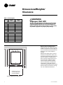
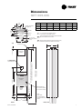
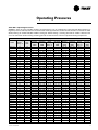
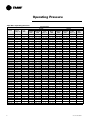
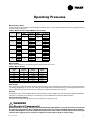
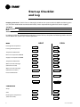
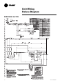
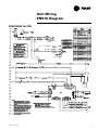
1
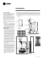
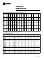
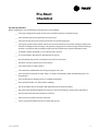
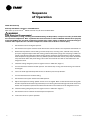
Installation
Owner
Diagnostics
Vertical Stack
Water-Source Heat Pump
Model GETB
Models
“A” and later Design Sequence
GETB
009-036 – 60 HZ
009-036 – 50 HZ
February 2006
WSHP-SVN08B-EN
Notice
NOTICE:
Warnings and Cautions appear at appropriate sections throughout this manual.
Read these carefully.
!
WARNING – Indicates a potentially hazardous situation
which, if not avoided, could result in death or serious
injury.
!
CAUTION – Indicates a potentially hazardous situation
which, if not avoided, may result in minor or moderate
injury. It may also be used to alert against unsafe practices.
CAUTION – Indicates a situation that may result in
equipment or property-damage-only accidents.
Important!
Equipment is shipped FOB (Free on Board) at the
manufacturer. Therefore, freight claims for damages
against the carrier must be initiated by the receiver.
NOTICE:
Unit contains HCFC (R-22) Refrigerant
Instructions!
Section 608, Paragraph C of the 1990 Clean Air Act states:
Effective July 1, 1992, it shall be unlawful for any person, in course of
maintaining, servicing, repairing, or disposing of an air conditioning system, to
knowingly vent or release any CFC or HCFC refrigerant. Minimal releases (air
purges or refrigerant hoses) associated with good faith attempts to recapture or
recycle are exempt from the ban on venting.
Responsible Refrigerant Practices!
Trane believes that responsible refrigerant practices are important to the
environment, our customers, and the air conditioning industry. All technicians
who handle refrigerants must be certified. The Federal Clean Air Act (Section 608)
sets forth the requirements for handling, reclaiming, recovering and recycling of
certain refrigerants and the equipment that is used in these service procedures.
In addition, some states or municipalities may have additional requirements that
must also be adhered to for responsible management of refrigerants. Know the
applicable laws and follow them.
© 2006 American Standard Inc All rights reserved
WSHP-SVN08B-EN
Contents
Installation/Startup/Commissioning
WSHP-SVN08B-EN
4
Pre-installation Checklist
4
General Information
5
Dimensions/Weights
6
Installation Instructions
9
Electrical Requirements
18
Pre-Startup Checklist
19
Startup/Commissioning
20
Sequence of Operation
20
Operating Pressures
21
Startup Checklist & Log
24
Maintenance
25
Warranty Information
26
Troubleshooting Checklist
27
Unit Wiring
29
3
Pre-installation
Checklist
! WARNING
Fiberglass Wool!
Product contains fiberglass wool. Disturbing the insulation in this
product during installation, maintenance or repair will expose you to
airborne particles of glass wool fibers and ceramic fibers known to the
state of California to cause cancer through inhalation. Glass wool fibers
may also cause respiratory, skin or eye irritation.
Jobsite Inspection
Always perform the following checks before accepting a unit:
1. Verify that the nameplate data matches the data on the sales order and bill of
lading (including electrical data).
2. Verify that the power supply complies with the unit nameplate specifications.
3. Visually inspect the exterior of the unit, for signs of shipping damage. Do not
sign the bill of lading accepting the unit(s) until inspection has been completed. Check for damage promptly after the unit(s) are unloaded. Once the
bill of lading is signed at the jobsite, the unit(s) are now the property of the
SOLD TO party and future freight claims MAY NOT be accepted by the freight
company.
4. Verify that the refrigerant charge has been retained during shipment by use
of gauges. Schrader taps are located external to the cabinet on the 2-ton
through 6-ton equipment.
5. After assuring that charge has been retained, reinstall the schrader caps to
assure that refrigerant leakage does not occur.
CAUTION
Microbial Growth!
Wet interior unit insulation can become an amplification site for
microbial growth (mold), which may cause odors and damage to the
equipment and building materials. If there is evidence of microbial
growth (mold) on the interior insulation, the insulation should be
removed and replaced prior to operating the system.
Jobsite Storage
This unit is intended for indoor use only. To protect the unit from damage due to
the elements, and to prevent possible IAQ contaminant sources from growing,
the unit should be stored indoors. If indoor storage is not possible, the following
provisions for outdoor storage must be met:
1. Place the unit(s) on a dry surface or raise above the ground to assure adequate air circulation beneath the unit.
2. Cover the unit(s) with a water proof tarp to protect them from the elements.
3. Make provisions for continuous venting of the covered units to prevent
moisture from standing on the unit(s) surfaces. Wet interior unit insulation
can become an amplification site for microbial growth (mold) which has
been determined to be a cause of odors and serious health related indoor air
quality problems.
4. Store refrigeration units (chassis) units in the normal UP orientation to maintain oil in the compressor. Cabinet configurations may be stored as crated.
5. Do not stack units.
4
WSHP-SVN08B-EN
General
Information
Unit Nameplate
The unit nameplate is located at the
front of the unit. It includes the unit
model number, serial number, electrical characteristics, refrigerant charge,
and other pertinent unit data.
Compressor Nameplate
The nameplate for the compressors
are located on the compressor shell.
Unit Description
Before shipment, each unit is leak tested, dehydrated, charged with refrigerant and run tested for proper control
operation.
Water-to-Refrigerant Coils
The co-axial water-to-refrigerant heat
exchanger for the 3/4-ton through 3ton equipment is constructed of copper or cupro-nickel (option) for the water section and stainless steel for the
refrigeration section.
The heat exchanger is leak tested to
assure there is no cross leakage between the water and refrigerant gas.
Water Connections
1/2" or 3/4" water connections are located on the chassis’s upper section
and clearly labeled for water-in/out
hose to riser hook-up.
Blower/Motor
The blower and motor is located inside
the unit cabinet. The blower and motor
may be removed from the cabinet
through the chassis opening. After removing the chassis, the blower assembly is strapped into the unit
cabinet through a single metal, flexible bracket. We refer to this bracket as
a housing belly bracket. After detaching one screw at the bottom/front edge
of the bracket, the housing and motor
are free to be lifted from the fan deck.
WSHP-SVN08B-EN
Sound Attenuation
Sound attenuation is applied as a standard feature in the product design. The
enhanced reduction package includes
a heavy gage base plate, and gasket/
insulation around the compressor enclosure.
An optional deluxe sound reduction
package is also available. It includes a
heavy gage base plate, gasket and insulation around the compressor enclosure, and vibration isolation between
the chassis and cabinet. An additional
dampening treatment is applied
around the compressor enclosure to
achieve greater acoustical reductions.
Controls
The control system offered to control
the unit is a Basic 24 volt control for
the 3/4-ton through 2-ton retrofit
(WPRD) equipment. A 50 VA transformer is factory supplied on this unit
configuration. See wiring diagram on
chassis access panel for field wiring
connection to the 24 volt mechanical
thermostat.
ZN510 Controls
(GET option)
Units incorporating the ZN510 control
option design will include a digital
LonTalkTM certified control board. The
control board will support such options as: random start delay, heating/
cooling status, occupied/unoccupied
mode and fan/filter status.
Power wiring is made at the contactor.
The wiring is fed through the left or
right conduit tube, and into the cabinet’s control box (contactor). See
manual WSHP-IOP-2 for diagnostic information.
Schrader Connections
Connections for the low and high side
of the refrigeration system are located
conveniently on the chassis’ top beneath a sheet metal plate.
Deluxe 24V Controls
(GET model)
Units containing the Deluxe 24V control design will incorporate a microprocessor-based control board. The
Trane microprocessor board is factory
wired to a terminal strip to provide all
necessary terminals for field connection. The deluxe board is equipped
with a random start relay, anti-short
cycle timer, brown out protection,
compressor disable, unit safety control, diagnostics and a generic relay
(which may be available for field use).
See page 16 for diagnostic information.
Power wiring is made at the contactor.
The wiring is fed through the left or
right conduit tube, and into the cabinet’s control box (contactor).
5
Dimensions/Weights/
Clearance
Table 1: Unit weights
Size
Shipping
Weight
with pallet (lb)
Shipping
Weight
w/o pallet (lb)
Cabinet
009
135
012
135
115
115
015
175
150
018
175
150
024
225
195
036
225
195
! WARNING
Improper Unit Lift!
Test lift unit approximately 24 inches to verify proper
center of gravity lift point. To avoid dropping of unit,
reposition lifting point if unit is not level. Failure to
properly lift unit could result in death or serious injury
or possible equipment or property-only damage.
Chassis
009
90
80
012
95
85
015
110
100
018
115
105
024
190
180
036
200
190
R
S
D
Unit Location and Clearances
Locate the unit in an indoor area. The
ambient temperature surrounding the
unit must not be less than 45°F. Do not
locate the unit in areas subject to
freezing.
Attention should be given to service
clearance and technician safety. The
unit chassis should be easily removed
from the cabinet in all applications.
There must be enough space for service personnel to perform maintenance or repair. Provide sufficient
room to make water, and electrical
connection(s). Local and national
codes should be followed in providing
electrical power connections. See Figure 1 for mechanical clearances.
ALLOW 36" (914 mm)
AT UNIT FRONT FOR
CHASSIS REMOVAL
Figure 1: Mechanical clearances
6
WSHP-SVN08B-EN
Dimensions
GET 009-036
12 1/2"
(318)
8" (203)
S
D
3 3/4"
(95)
VARIES DEPENDENT
ON RISER O.D.
009, 012
B
C
16 1/4" (413) 16 1/4" (413)
8 1/8" (206)
D
E
F
39 1/8" (994)
14 3/4" (375)
3/4" (19)
015-018
18" (457)
20" (508)
10" (254)
40 5/8" (1032) 18 3/4" (476)
3/4" (19)
024-036
24" (610)
24" (610)
12" (305)
49 5/8" (1260) 22 5/8" (575)
3/4" (19
1" (25.4)
SUPPLY
G
11" (279) FOR 80" (2032) CABINET HEIGHT
3" (76) FOR 88" (2235) CABINET HEIGHT
H
SUPPLY-AIR OPENINGS AND RISER LOCATIONS CANNOT
BE ON THE SAME SIDE OF THE UNIT.
J
RISER LOCATION CAN BE ON ANY SIDE EXCEPT FRONT,
AND MAY BE SUPPLIED BY TRANE OR BY OTHERS.
DRAIN
1/2" (12.7) O.D.
ELECTRIC CONDUIT
1" (25.4)
B
TOP
A
RETURN
OPTIONAL
DUCT OPENING
1" (12.7) DUCT
COLLAR
1"
(25.4)
12 1/2"
(318)
8" (203)
3 3/4"
(95) R
GET
SWAGE 3" (76)
A
G
UNITS WITH TOP DISCHARGE ARE 80" (2032) IN HEIGHT
ALL OTHER UNITS ARE 88" (2235) IN HEIGHT
LOW VOLTAGE
CONNECTION BOX
FOR THERMOSTAT
C
CONTROL BOX
60" (1524)
THROWAWAY
FILTER
CHASSIS
ACCESS
PANEL
4 3/4"
(121)
DRAIN
CONNECTION
3/4" (19) O.D.
F
FRONT
WSHP-SVN08B-EN
2 1/2" (63.5)
D
FROM 96" (2438)
TO 120" (3048)
1 1/4" (32)
SUPPLY-AIR
OPENING
RISER CONNECTION
1/2” (13) NPTE = 009-018
3/4” (19) NPTE = 024,036
NOTE:
RIGHT RISER
LOCATION SHOWN
IN FRONT AND RIGHT
VIEWS.
E
RIGHT SIDE
7
Dimensions
Hinged Acoustical Door
Return Air (hinged)
Acoustical Door
The hinged acoustical door is recessed
into the wall so that the door is flush
with the surface of the wall.
3 1/2” ±3/8”
A
2“ X 4” STUD
1 1/4”
+1/2”/-0”
SHEETROCK
The opening through the wall
for the door assembly must be
centered with the return-air
opening of the unit cabinet.
For full installing instructions
of the return-air acoustical
door, see page 12.
B
CABINET
1“ X 1” CLOSED
CELL INSULATION
RETURN AIR OPENING
FLANGE ON CABINET
Unit Size
A
B
09
012
19 1/4”
(489)
44 1/8”
(1121)
015
018
23 1/4”
(591)
45 1/4”
(1149)
024
036
27 1/8”
(689)
54 5/8”
(1387)
SHEETROCK
A
2“ X 4”
STUD
Note:
Finished wall and framing should not
touch the unit cabinetry.
1 1/4”
+1/2”/-0”
SHEET ROCK
OPENING
1“ X 1” CLOSED
CELL INSULATION
RETURN AIR
DOOR FLANGE
RETURN AIR OPENING
FLANGE ON CABINET
TOP VIEW
CABINET
3 1/2” ±3/8”
SHEETROCK
RETURN AIR
DOOR FRAME
2 X 4 STUD
RETURN-AIR OPENING
FLANGE ON CABINET
1“ X 1” CLOSED
CELL INSULATION
B
1“ X 1” CLOSED
CELL INSULATION
RETURN-AIR OPENING
FLANGE ON CABINET
RETURN AIR
DOOR FRAME
2 1/4“
SHEETROCK
5“
CABINET
FLOOR
1 1/2” X 2 3/8”
4 5/8“
3 1/2” ±3/8”
SIDE VIEW
8
WSHP-SVN08B-EN
Installation
General Installation Checks
The checklist below is a summary of
the steps required to successfully install a unit. This checklist is intended to
acquaint the installing personnel with
procedures required in the installation
process. It does not replace the detailed instructions called out in the applicable sections of this manual.
1
Remove packaging and inspect the
unit. Check the unit for shipping
damage and material shortage; file
a freight claim and notify appropriate sales representation.
Note: The unit cabinet is packaged
in a wooden crate. A pry bar and/
or hammer will be needed for
packaging removal.
The chassis sits inside a cardboard
tray with an upper box for protection. Typically four chassis will be
shrink-wrapped to a single pallet.
2
Verify the correct model, options
and voltage from the unit nameplate.
3
Verify the installation location of
the unit will provide the required
clearance for proper operation.
4
WSHP-SVN08B-EN
Remove refrigeration access panel
and inspect the unit. Be certain the
refrigerant tubing has clearance
from adjacent parts.
WARNING
Hazardous
Voltage!
!
Disconnect all electric power,
including remote disconnects and
discharge all motor start/run
capacitors before servicing.
Follow proper lockout/tagout
procedures to ensure the power
can not be inadvertently
energized. Failure to disconnect
power before servicing could
result in death or serious injury.
Main Electrical
5 Verify the power supply complies
with the unit nameplate specifications.
6
Inspect all control panel components; tighten any loose connections.
7
Connect properly sized and protected power supply wiring to a
field-supplied/installed disconnect
switch and to the unit power block
(1TB1) in the unit’s cabinet control
box for equipment.
8
Install proper grounding wires to
an earth ground.
Note: All field-installed wiring must
comply with NEC and applicable local
codes.
Low Voltage Wiring (AC & DC)
Requirements
9 Connect properly sized control wiring to the proper termination
points between the field supplied
thermostat and the terminal plug
in the equipment’s junction box.
9
Installation
! WARNING
expansion slots. The stubouts
should be perpendicular to the cabinet panel.
Improper Unit Lift!
Test lift unit approximately 24
inches to verify proper center of
gravity lift point. To avoid
dropping of unit, reposition lifting
point if unit is not level. Failure to
properly lift unit could result in
death or serious injury or possible
equipment or property-only
damage.
7 Verify all risers are vertical and that
they penetrate the swaged joint at
least 1". Riser should not be allowed to bottom out.
Unit Placement
If unit cabinet assembly includes factory provided risers, and "no" field
provided between-the-floor riser extensions, please move to Step 1.
9 If risers are field provided, it is recommended that the risers be anchored to the building structure
with a minimum of one contact
point. For expansion and contraction reasons, do not fasten risers
rigidly to the building.
Note: Risers are designed to accommodate a maximum of 1 1/2" to 3" expansion and contraction. If the total
calculated riser expansion exceeds 3",
expansion devices must be field provided.
FLOOR
3" SWAGE
If unit cabinet assembly includes factory provided risers and field provided
between-the-floor riser extensions are
required, install the extensions before
installing the cabinet.
1 Install drain valve, shut-off/balancing valves, flow indicators and
drain at the base of each supply and
return riser to enable system flushing at start-up, balancing and service/maintenance.
2 Lift cabinet into space while aligning it into the 3"swage of the riser
below.
Note: Take extra care as not to scrape
or dent risers during positioning. The
riser should fall approximately 2" into
the 3" swage. This will allow for the
variation in floor-to-floor dimensions,
and keep the riser joints from bottoming out.
FLOOR
Figure 2: Stacking illustration
3 Level the cabinet.
4 Plumb risers in two planes to assure proper unit operation and condensate drainage.
5 Anchor all units into place.
6 For field provided risers, center the
supply/return stubouts into the unit
10
8 Braze riser joints. Soft solder or
low-temperature alloys should not
be used in this application.
10 Seal access holes made through the
cabinet for piping with suitable material to help eliminate air leakage.
11 See page 14 for system flushing.
Water Connection
For vibration isolation, it is recommended that flexible steel braided
hoses be installed instead of hard piping between the vertical risers and the
unit chassis.
Trane offers 4-types of hose kit variations:
•
Stainless steel braided flexible
hose with manual shut-off (ball)
valves
•
Stainless steel braided flexible
hose with manual deluxe shut-off
(ball) valves
•
Stainless steel braided flexible
hose with manual circuit-setter
valve
•
Stainless steel braided flexible
hose with automatic balancing
valve
Additional accessories, such as a
strainer are recommended for use to
eliminate contaminants from entering
the co-axial water-to-refrigerant heat
exchangers.
WSHP-SVN08B-EN
Installation
Field Installed Power Wiring
Power wiring to the equipment must
conform to National and Local Electric
Codes (NEC) by a professional electrician.
The high voltage connection is made
at the 1PB1 power block in the cabinet
control box. Refer to the customer
connection diagram that is shipped
with the unit for specific termination
points.
! WARNING
Live Electrical
Components!
Provide proper grounding for the unit
in accordance with the local and national codes.
During installation, testing, servicing and troubleshooting of this
product, it may be necessary to
work with live electrical components. Have a qualified licensed
electrician or other individual
who has been properly trained in
handling live electrical components perform these tasks. Failure
to follow all electrical safety precautions when exposed to live
electrical components could result in death or serious injury.
Verify that the power supply available
is compatible with the unit’s nameplate. Use only copper conductors to
connect the power supply to the unit.
CAUTION
Use Copper
Conductors Only!
Unit terminals are not designed
to accept other types of conductors. Failure to use copper conductors may result in equipment
damage.
Control Power Transformer
The 24-volt control power transformers are to be used only with the accessories called out in this manual.
Transformers rated greater than 50 VA
are equipped with internal circuit
breakers. If a circuit breaker trips, turn
OFF all power to the unit before attempting to reset it.
FACTORY CONDUIT
Figure 3: Power wire entrance
! WARNING
Hazardous Voltage!
Disconnect all electric power, including remote disconnects and
discharge motor start/run capacitors before servicing. Follow proper lockout/tagout procedures to
ensure the power can not be inadvertently energized. Failure to disconnect power before servicing
could result in death or serious injury.
The transformer is located in the
chassis control box.
Main Unit Power Wiring
A field supplied disconnect switch
must be installed at or near the unit in
accordance with the National Electric
Code (NEC latest edition).
Location of the applicable electric service entrance for HIGH (line voltage)
may be found in Figure 3.
1 Route power wire to the cabinet
control box through the factory installed conduit at the top of the unit
cabinetry.
WSHP-SVN08B-EN
11
Installation
4 Place the door frame into the sheet rock opening. A positive seal is critical between the back of the door frame and the front of the cabinet. Ensure that the
gasket material seals properly. Note: When placing the sheet rock panel, make
certain the opening for the door is centered with the return-air opening in the
cabinet (±1/8").
3 1/2” ±3/8”
A
2“ X 4” STUD
B
2 The height of the door assembly
must be positioned to recess the
door 2 1/4-inches from the cabinet’s
return-air opening, Figure 4 - Side
View blow-up.
3 Locate dimensions A and B for sheet
rock opening size. The position of
the sheet rock opening must be centered side-to-side with the return-air
opening in the cabinet. Ensure the
bottom of the sheet rock opening is
2 1/4-inches below the return-air
opening in the cabinet. This allows
the door recess to rest on the bottom of the sheet rock opening for
proper vertical placement of the
door.
SHEET ROCK
OPENING
1“ X 1” CLOSED
CELL INSULATION
1“ X 1” CLOSED
CELL INSULATION
RETURN AIR OPENING
FLANGE ON CABINET
Unit Size
A
B
09
012
19 1/4”
(489)
44 1/8”
(1121)
015
018
23 1/4”
(591)
45 1/4”
(1149)
024
036
27 1/8”
(689)
54 5/8”
(1387)
SHEETROCK
A
2“ X 4”
STUD
Note:
Finished wall and framing should not
touch the unit cabinetry.
1 1/4”
+1/2”/-0”
RETURN AIR OPENING
FLANGE ON CABINET
CABINET
1 Units that contain a field provided
return air access assembly, contractor must calculate location of drywall to allow for frame mounting.
Units utilizing Hinged Acoustic
Door Assembly.
1 Locate the side studs a minimum of
1 1/4-inches and a maximum of 1 3/
8-inches from the cabinet to the side
of the stud. This critical dimension,
combined with "distance between
studs" is used to determine the sideto-side opening for the door, dimension A. The distances provided in
the table are a "minimum" dimension. Allow 3 1/2-inches from the
front of the cabinet to the sheet rock
surface, Figure 4 - Top View. Figure
5, mock-up of stud placement.
1 1/4”
+1/2”/-0”
SHEETROCK
The location of the drywall may be dependent upon the type of return air access design.
RETURN AIR
DOOR FLANGE
Drywall Installation
Before installing drywall around cabinet. Cover the cabinet supply and return openings with plastic or
cardboard to help prevent dust or construction debris from reaching unit
components. Warranties will be voided if paint or foreign debris is allowed
to contaminate internal unit components.
TOP VIEW
CABINET
3 1/2” ±3/8”
SHEETROCK
RETURN AIR
DOOR FRAME
2 X 4 STUD
RETURN-AIR OPENING
FLANGE ON CABINET
1“ X 1” CLOSED
CELL INSULATION
B
Figure 5:
1“ X 1” CLOSED
CELL INSULATION
RETURN-AIR OPENING
FLANGE ON CABINET
RETURN AIR
DOOR FRAME
2 1/4“
SHEETROCK
5“
CABINET
FLOOR
1 1/2” X 2 3/8”
4 5/8“
3 1/2” ±3/8”
SIDE VIEW
Figure 4: Drywall installation for hinged acoustic door
12
WSHP-SVN08B-EN
Installation
1 Secure the door frame to the side
studs using the holes located in the
door frame and field provided
screws, Figure 6.
3 After verifying that the air panel gasket is sealed to the coil, secure the
air panel to the door frame using the
slots located on the sides of the air
panel, Figure 8.
Chassis Installation
1 Remove three 16-inch bolts on the
chassis and discard, Figure 9.
Figure 9: Shipping bolts
2 Rotate the triangular metal plate to
cover the bolt holes in the chassis.
Secure with two sheet metal screws.
Figure 6: Door opening
Note: If the gap between the door
frame, and the side stud is over 1/16inch, place a shim in between the door
frame and the stud to prevent the door
frame from bending/denting.
2 Place the air panel into the door
opening. The gasket on the back
side of the air panel should seal
around the coil perimeter, Figure 7.
Figure 7: Air panel gasket
Figure 8: Secure to door frame
4 Install Filter.
5 Vacuum all dust and construction
debris from unit after cutting out
supply/return openings.
Supply Air Ductwork
1 A 2" (50.8 mm) duct flange (field
provided) may be required to help
eliminate supply air from recirculating back into the return air, air-to-refrigerant coil prior to discharging
into the space.
2 Equipment containing a top discharge, ducted design: install field
ductwork to the unit providing a water tight flexible connector at the
unit. This helps prevent operating
sounds from transmitting through
the ductwork. Elbows with turning
vanes or splitters are recommended
to minimize air noise due to turbulence and to help reduce static pressure.
3 Remove two shipping brackets (one
on each side) attached to the chassis
slide rails and discard, Figure 10.
Note: Remove this bracket only if
the enhanced sound package design
is preferred.
Figure 10: Bracket removal for
enhanced sound package
4 Connect water coil pipe to the system riser with a flexible steel hose
assembly.
5 Verify that the shut-off/balancing
valve in the return line/supply line
are closed.
6 Place shut-off valves in appropriate
location (see sticker on the equipment for best placement recommendation) to allow chassis to slide
easily in/out of unit cabinetry.
WSHP-SVN08B-EN
13
Installation
! WARNING
Live Electrical
Components!
IMPORTANT
Ensure the gasket material creates a
positive seal around the entire coil to
avoid coil bypass.
During installation, testing, servicing and troubleshooting of this
product, it may be necessary to
work with live electrical components. Have a qualified licensed
electrician or other individual
who has been properly trained in
handling live electrical components perform these tasks. Failure
to follow all electrical safety precautions when exposed to live
electrical components could result in death or serious injury.
If a field supplied door is used, ensure
the front cover is attached to the building structure and not the unit cabinet.
7 Flush system. See Cleaning and
Flushing the Water Loop for flushing
instructions.
8 Open the unit water valves and
check piping for leaks.
9 Connect electrical to unit chassis via
the quick connect mating plugs.
Note: Four plugs are included (motor,
optional condensate overflow, power
and thermostat).
10 Slide chassis into the cabinet. Center the chassis left to right to minimize sound transmission. See
Figure 11.
Supply Grille installation
See Table 2 for supply air dimensions.
1
Install the supply grille(s) into the
cabinet discharge opening. Insure
there are no air gaps between the
cabinet supply air and the grille.
This helps prevent recirculation of
supply air into the return air opening behind the drywall.
2
Secure grille(s) into the drywall via
two screws.
5 With the air vented and the water
circulating, the entire system
should be checked for leaks with repairs made as required.
6 Operate the supplementary heat
system making checks per manufacturer’s instructions. During this
operation, visual checks should be
made for leaks that may have occurred due to increased heat. Repair as required.
7 Open the system at the lowest point
for the initial blow down (making
sure the make up water is equal to
the water being dumped). Continue
blow down until the water leaving
the drain runs clear, but not less
than 2 hours.
8 Shut down pumps and supplementary heat system. Reconnect the
hoses placing the water-to-refrigerant heat exchanger in the water circulating system.
Cleaning and Flushing
the Water Loop
After the piping system is complete,
the flexible hose connectors should be
doubled back to complete the water
circuit external to the unit (avoiding
trash settle-out in the condenser). An
extra pipe may be necessary to connect the hose kits. See Page 15 for antifreeze/water mixture by volume.
Note: Vents should be open when the
pumps and supplementary heat system are shut down.
CONNECTION
HOSE
3 Water circulation system should be
filled with clean water using the water make up connections. Note: Air
vents should be opened during filling.
WATER-SOURCE
HEAT PUMP
TEMPORARY
CONNECTION
FOR SYSTEM
FLUSHING
4 With the air vents closed, start the
circulating pump and then crack the
air vents to bleed off the trapped
air, assuring circulation through all
components of the system.
Note: Make up water must be available
to the system to replace the volume
formerly occupied by the air that is
bled off.
Figure 11: Install chassis centered
11 Verify unit’s air filter is properly
place in the chassis filter rack.
12 Install cabinet’s front cover to the
hinged door.
14
CIRCULATING
PUMP
GROUND-LOOP
OR
COOLING TOWER/BOILER
Figure 12: Flushing the water loop
Table 2: Supply air opening size
GET
Model
Single Grille
100% CFM
Two Grille
50% CFM
Three Grille
33% CFM
Top Discharge
Up to 100%
CFM
009, 012
12W x 10H
(305 x 254)
10W x 6H
(254 x 152)
Not
Recommended
14 x 10
(356 x 254)
015, 018,
024
14W x 12H
(356 x 305)
14W x 12H
(356 x 305)
12W x 8H
(305 x 203)
16 x 14
(406 x 356)
036
Not
Recommended
16W x 14H
(406 x 356)
14W x 12H
(356 x 305)
17 x 17
(432 x 432)
WSHP-SVN08B-EN
Installation
Using Antifreeze
In areas of the country where entering
water temperatures drop below 45°F
or where piping is being run through
areas subject to freezing, the loop
must be freeze protected by using an
approved antifreeze solution to prevent the earth loop water from freezing inside the heat exchanger.
Methanol and glycols are the most
commonly used antifreeze solutions.
Consult your geothermal unit supplier
for locally approved solutions in your
area.
Table 3: Antifreeze requirements based on volume
Type of Antifreeze
Minimum Temperature for Freeze Protection
10°F
15°F
20°F
25°F
30°F
Methanol
25%
21%
16%
10%
3%
Propylene Glycol
-
-
-
-
6%
Propylene glycol is not recommended
in installations where the water temperature are expected to fall below
30°F. At extreme temperatures, the viscosity increases to the point where
normal loop circulating pumps may
not maintain proper flow.
If propylene glycol is the only locally
approved solution for anti-freeze,
good engineering practices should be
used to achieve the desired flow.
Calculate the approximate volume of
water in the system by using the requirements detailed in Table 8, Water
Volume. Add three gallons to this total
to allow for the water contained in the
hose kit and geothermal unit.
WSHP-SVN08B-EN
15
Installation
Low Voltage Wiring
Low Voltage Wiring
Factory ordered thermostats and zone
sensors are pre-wired with a quick
connecting plug.
Factory provided plug
1 After installing the cabinet assembly, simply plug the male portion of
thermostat/zone sensor plug into
the female portion of the plug located inside the unit’s junction box.
2 Mount the thermostat or zone sensor on the finished drywall.
Six (6) Pin Connector/Harness
Red = 24V
Black = Fan
Orange = RV
Yellow = Compressor
Blue = Common
Thermostat/zone sensor connection is
shown in Figure 13.
Low Voltage Wiring for Field
Provided Thermostats/Zone
Sensors
Ensure that the AC control wiring between the controls and the unit’s termination point does not exceed three
(3) ohms/conductor for the length of
the run.
Note: Resistance in excess of 3-ohms
per conductor may cause component
failure due to insufficient AC voltage
supply.
Check all loads and conductors for
grounds, shorts, and mis-wiring.
Use copper conductors unless otherwise specified.
Do not run the AC low voltage wiring
in the same conduit with the high voltage power wiring.
Table 4: 24V AC conductors
Distance from unit
to Control
Recommended
Wire Size
000-460 feet
18 gauge
461-732 feet
16 gauge
733-1000 feet
14 gauge
16
Figure 13: Zone sensor connection
Table 5: Deluxe controller diagnostic LEDs
Color: Green
LED1
Color: Red
LED2
LED3
Controller Mode
OFF
OFF
OFF
Control OFF
ON
OFF
OFF
Normal/Compressor OFF
ON
OFF
FLASH
Anti-short Cycle
ON
OFF
ON
Normal/Compressor ON
FLASH
ON
OFF
Brownout Condition
ON
FLASH
ON
Soft Lockout (low pressure)
ON
FLASH
FLASH
Soft Lockout (high pressure)
ON
ON
ON
Manual Lockout (low pressure)
ON
ON
FLASH
Manual Lockout (high pressure)
ON
FLASH
OFF
Manual Lockout (condensate overflow)
ON
ON
OFF
Compressor Disable
WSHP-SVN08B-EN
Installation
Air Flow Adjustment
Blower Motor Speed Retrofit
Motors installed in the unit have multiple speed configurations. To modify
the rpm of the motor, the following
steps may be followed.
1
2
3
4
! WARNING
Hazardous Voltage!
Disconnect all electric power, including remote disconnects and
discharge motor start/run capacitors before servicing. Follow proper lockout/tagout procedures to
ensure the power can not be inadvertently energized. Failure to disconnect power before servicing
could result in death or serious injury.
5
Locate the blower motor relay inside the chassis control box.
Remove the undesired speed tap.
Select desired speed tap wire by
using information from Table 7.
Connect desired tap wire to the
1K4 relay at spade 4.
Reconnect power to the unit.
Table 6: Lead change
Lead Colors
Lead Speed
High
Low
Blower
1G
9A
Table F1: Blower External Static Pressure without Return Air Door (RAD), with filter
Model Speed
Min Max
Ducted
No.
Tap
CFM CFM
0
GET009 High
Yes
280 482
GET009 Low
Yes
GET009 High
No
350
GET009 Low
No
285
GET012 High
Yes
380 481
GET012 Low
Yes
GET012 High
No
492
GET012 Low
No
402
GET015 High
Yes
475 652
GET015 Low
Yes
GET015 High
No
585
GET015 Low
No
485
GET018 High
Yes
570 800
GET018 Low
Yes
GET018 High
No
713
GET018 Low
No
552
GET024 High
Yes
760 974
GET024 Low
Yes
GET024 High
No
987
GET024 Low
No
807
GET036 High
Yes
1135 1344
GET036 Low
Yes
GET036 High
No
1324
GET036 Low
No
1229
1
2
3
0.05
456
341
442
582
648
878
1271
-
0.1
422
329
422
566
642
853
1263
-
0.15
383
309
481
404
551
628
836
1253
-
0.2
347
283
458
384
535
613
974
814
1238
-
External Static Pressure (in. of wg)
0.25
0.3
0.35
0.4
0.45
0.5
308
435
411
385
652
631
611
584
561
535
519
505
486
799
772
747
723
596
580
954
927
905
877
846
824
793
773
1344
1230 1213 1196 1178 1155
-
0.55
503
693
790
1313
-
0.6
467
664
1282
-
0.65
429
632
1255
-
0.7
689
603
1219
-
The NO "Ducted" option is for non-ducted (free return) units.
Units specified as "non-ducted" (free return) are factory wired to low-speed.
Units specified as "ducted" are factory wired to high-speed.
WSHP-SVN08B-EN
17
Electrical
Requirements
Table F2: Blower External Static Pressure with Return Air Door (RAD), with filter
External Static Pressure (in.
Speed
Min
Max
Ducted
Tap
CFM
CFM
0
0.05 0.1 0.15 0.2 0.25 0.3 0.35 0.4
GET009
High
Yes
280
482
451
417
378
342
303
GET009
Low
Yes
336
324
304
278
GET009
High
No
345
GET009
Low
No
280
GET012
High
Yes
380
481
459
436
413
389
363
GET012
Low
Yes
420
400
382
362
GET012
High
No
470
GET012
Low
No
380
GET015
High
Yes
475
652
642
621
601
574
GET015
Low
Yes
572
556
541
525
509
495
476
GET015
High
No
575
GET015
Low
No
475
GET018
High
Yes
570
800
774
747
GET018
Low
Yes
623
617
603
588
571
555
GET018
High
No
690
GET018
Low
No
524
GET024
High
Yes
760
974
927
907
880
858
830
GET024
Low
Yes
831
806
789
767
746
726
GET024
High
No
940
GET024
Low
No
760
GET036
High
Yes
1135 1344
GET036
Low
Yes
1177 1169 1159 1144 1136 1119 1102 1084
GET036
High
No
1280
GET036
Low
No
1140
1
The NO "Ducted" option is for non-ducted (free return) units.
2
Units specified as "non-ducted" (free return) are factory wired to low-speed.
3
Units specified as "ducted" are factory wired to high-speed.
Model No.
of wg)
0.45 0.5 0.55 0.6 0.65 0.7
551
525
493
457
419
679
722
698
668
639
607
578
799
777
743
1250 1219 1188 1161 1125
1061
-
Table E1: Electrical Performance
18
Model No.
Oversized Blower
Volts
Total
FLA
Comp.
RLA
Comp.
LRA
GET009
GET009
GET009
GET009
GET012
GET012
GET012
GET012
GET015
GET015
GET015
GET015
GET018
GET018
GET018
GET018
GET024
GET024
GET024
GET024
GET036
GET036
GET036
GET036
No
No
No
No
No
No
No
No
No
No
No
No
No
No
No
No
No
No
No
No
No
No
No
No
208/60/1
220-240/50/1
230/60/1
265/60/1
208/60/1
220-240/50/1
230/60/1
265/60/1
208/60/1
220-240/50/1
230/60/1
265/60/1
208/60/1
220-240/50/1
230/60/1
265/60/1
208/60/1
220-240/50/1
230/60/1
265/60/1
208/60/1
220-240/50/1
230/60/1
265/60/1
4.0
3.6
4.0
3.6
5.7
4.9
5.7
4.9
6.1
5.4
6.1
5.4
9.3
7.4
9.3
7.4
13.1
11.7
13.1
11.7
19.3
16.4
19.3
16.4
3.4
3.1
3.4
3.1
5.0
4.3
5.0
4.3
5.4
4.8
5.4
4.8
7.6
6.3
7.6
6.3
10.9
9.9
10.9
9.9
16.0
13.6
16.0
13.6
22.2
18.8
22.2
18.8
27.9
22.2
27.9
22.2
29.0
27.0
29.0
27.0
45.0
32.0
45.0
32.0
56.0
55.0
56.0
55.0
82.0
64.0
82.0
64.0
Blower
Motor
FLA
0.6
0.5
0.6
0.5
0.7
0.6
0.7
0.6
0.7
0.6
0.7
0.6
1.7
1.1
1.7
1.1
2.2
1.8
2.2
1.8
3.3
2.8
3.3
2.8
Blower
Motor
HP
1/10
1/10
1/10
1/10
1/8
1/8
1/8
1/8
1/8
1/8
1/8
1/8
1/5
1/5
1/5
1/5
1/5
1/5
1/5
1/5
1/2
1/2
1/2
1/2
Minimum
Circuit
Ampacity
4.9
4.4
4.9
4.4
6.9
6.0
6.9
6.0
7.5
6.6
7.5
6.6
11.2
9.0
11.2
9.0
15.8
14.2
15.8
14.2
23.3
19.8
23.3
19.8
Overcurrent
Protective
Device
15
15
15
15
15
15
15
15
15
15
15
15
15
15
15
15
25
20
25
20
35
30
35
30
WSHP-SVN08B-EN
Pre-Start
Checklist
Pre-Start-up Checklist
Before energizing the unit, the following system devices must be checked:
____ Is the high voltage power supply correct and in accordance with the nameplate ratings?
____ Is the field wiring and circuit protection the correct size?
____ Is the low voltage control circuit wiring correct per the unit wiring diagram?
____ Is the piping system clean/complete and correct? (A recommendation of all system flushing of debris from
the water-to-refrigerant heat exchanger, along with air purging from the water-to-refrigerant heat exchanger
be done in accordance with the Closed-Loop/Ground Source Heat Pump Systems Installation Guide).
____ Is vibration isolation provided? (i.e. unit isolation pad, hose kits)
____ Is unit serviceable? (See clearance specifications on page 6).
____ Are the low/high-side pressure temperature caps secure and in place?
____ Are all the unit access panels secure and in place?
____ Is the thermostat in the OFF position?
____ Is the water flow established and circulating through all the units?
____ Is the duct work (if required) correctly sized, run, taped, insulated and weather proofed with proper unit
arrangement?
____ Is the condensate line properly sized, run, trapped and pitched?
____ Does the indoor blower turn freely without rubbing?
____ Has all work been done in accordance with applicable local and national codes?
____ Has heat transfer fluid been added in the proper mix to prevent freezing in closed system application?
____ Are the compressor bolts removed from the chassis?
____ Have the chassis isolation rails been released?
____ Is there a good seal between the front air panel and the coil?
WSHP-SVN08B-EN
19
Sequence
of Operation
Initial Unit Start-up
Start-up with deluxe controls is included below:
Note: Start-up for the TracerTM ZN510 controller may be found in WSHP-IOP-2.
! WARNING
Live Electrical Components!
During installation, testing, servicing and troubleshooting of this product, it may be necessary to work with
live electrical components. Have a qualified licensed electrician or other individual who has been properly
trained in handling live electrical components perform these tasks. Failure to follow all electrical safety precautions when exposed to live electrical components could result in death or serious injury.
20
1.
Set the thermostat to the highest position.
2.
Set the thermostat system switch to COOL with the fan control to AUTO. The compressor should NOT run.
3.
Reduce the temperature control setting until the compressor, reversing valve, solenoid valve, and loop
pump are energized. Adjust water flow utilizing pressure/temperature plugs and comparing to tables contained in specification sheet data. Water leaving the heat exchanger should be warmer than the entering
water temperature (approximately 9°F-12°F); blower operation should be smooth; compressor and blower
amps should be within data plate ratings; the suction line should be cool with no frost observed in the
refrigerant circuit.
4.
Check the cooling refrigerant pressures against values in Table OP1. (Page 21).
5.
Turn the thermostat switch to the OFF position. Unit should stop running and the reversing valve should
de-energize.
6.
Leave unit off for approximately FIVE minutes to allow for pressure equalization.
7.
Turn the thermostat to the lowest setting.
8.
Set the thermostat system switch to the HEAT position.
9.
Adjust the temperature setting upward until the unit is energized. Warm air should blow from the register.
A water temperature decrease of approximately 5°F-9°F leaving the heat exchanger should be noted. The
blower and compressor operation should be smooth with no frost observed in the refrigeration circuit.
10.
Check the heating refrigerant pressures against values in Table OP1. (Page 21)
11.
Set the thermostat to maintain the desired space temperature.
12.
Instruct the owner on system operation.
WSHP-SVN08B-EN
Operating Pressures
Table OP-1: Operating Pressures
GENERAL: There are many variables (airflow, air temperatures) in an air conditioning system that will affect operating refrigerant pressures and temperatures. The chart below shows approximate conditions and is based on air flow at the rated
SCFM, entering air at 80.6 °FDB, 66.2 °FWB in cooling, 68 °FDB in heating. (+)Heating data with 35 °F EWT is based on the
use of an anti-freeze solution having a freezing point 20 °F lower than the minimum expected entering temperature.
Operating Data
Water
Flow
GPM
Cooling
Heating
Model
Entering
Water
Temp, °F
GET 009
35
1.8
46 - 52
158 - 201
5-6
11 - 15
GET 009
35
2.25
46 - 53
159 - 203
4-5
12 - 15
GET 009
45
1.8
68 - 78
100 - 127
11 - 14
11 - 15
55 - 63
171 - 218
6-7
13 - 17
GET 009
45
2.25
68 - 78
97 - 123
9 - 11
12 - 15
56 - 65
172 - 219
5-6
14 - 18
GET 009
55
1.8
70 - 80
117 - 148
11 - 14
11 - 14
65 - 75
182 - 231
7-9
15 - 19
GET 009
55
2.25
70 - 80
113 - 144
9 - 11
12 - 15
66 - 76
183 - 233
6-7
16 - 20
GET 009
68
1.8
73 - 84
142 - 180
10 - 13
11 - 14
78 - 90
193 - 246
8 - 10
18 - 22
GET 009
68
2.25
73 - 84
138 - 176
9 - 11
12 - 15
79 - 91
195 - 248
7-9
18 - 23
GET 009
75
1.8
75 - 86
157 - 199
10 - 13
11 - 14
85 - 98
201 - 256
9 - 11
19 - 24
GET 009
75
2.25
74 - 86
153 - 195
8 - 11
11 - 15
87 - 100
202 - 257
7-9
19 - 25
GET 009
86
1.8
77 - 88
183 - 233
10 - 13
11 - 14
96 - 110
208 - 265
10 - 13
21 - 26
GET 009
86
2.25
76 - 88
179 - 227
8 - 11
11 - 15
98 - 113
209 - 266
8 - 10
21 - 27
GET 009
95
1.8
78 - 90
206 - 262
10 - 13
11 - 14
GET 009
95
2.25
78 - 90
202 - 257
8 - 10
11 - 14
GET 012
35
2.5
44 - 50
160 - 204
5-6
19 - 24
GET 012
35
3.1
45 - 51
162 - 206
4-5
19 - 24
GET 012
45
2.5
68 - 78
106 - 135
10 - 13
18 - 23
54 - 62
170 - 217
5-7
21 - 27
GET 012
45
3.1
67 - 77
102 - 130
9 - 11
19 - 24
55 - 63
172 - 219
4-6
22 - 27
GET 012
55
2.5
72 - 83
124 - 158
10 - 13
18 - 23
64 - 74
181 - 230
6-8
24 - 31
GET 012
55
3.1
71 - 82
120 - 153
9 - 11
18 - 23
65 - 75
182 - 232
5-7
25 - 31
GET 012
68
2.5
74 - 86
152 - 193
10 - 13
17 - 22
75 - 86
192 - 245
7-9
27 - 35
GET 012
68
3.1
74 - 85
147 - 187
8 - 11
18 - 23
76 - 87
194 - 247
6-8
28 - 36
GET 012
75
2.5
76 - 87
168 - 213
10 - 13
17 - 21
79 - 90
196 - 250
8 - 10
29 - 37
GET 012
75
3.1
75 - 86
163 - 207
8 - 10
17 - 22
79 - 91
198 - 252
6-8
29 - 37
GET 012
86
2.5
77 - 89
195 - 248
10 - 12
16 - 20
84 - 96
203 - 258
8 - 11
30 - 39
GET 012
86
3.1
77 - 88
190 - 242
8 - 10
16 - 21
85 - 97
204 - 260
7-9
31 - 39
GET 012
95
2.5
79 - 91
219 - 279
9 - 12
15 - 19
78 - 90
214 - 273
8 - 10
15 - 19
Suction
Pressure,
PSIG
Discharge
Pressure,
PSIG
Water
Temp
Rise, °F
Air Temp
Drop,
°FDB
Suction
Pressure,
PSIG
Discharge
Pressure,
PSIG
Water
Temp
Drop, °F
Air Temp
Rise,
°FDB
GET 012
95
3.1
GET 015
35
2.8
42 - 49
161 - 204
5-7
16 - 20
GET 015
35
3.5
44 - 51
163 - 208
4-6
16 - 20
GET 015
45
2.8
71 - 81
100 - 127
12 - 15
16 - 20
51 - 59
171 - 217
6-8
18 - 23
GET 015
45
3.5
71 - 81
97 - 124
10 - 12
16 - 21
53 - 61
174 - 221
5-7
19 - 24
GET 015
55
2.8
73 - 84
116 - 147
12 - 15
16 - 20
61 - 70
181 - 231
8 - 10
21 - 26
GET 015
55
3.5
73 - 84
112 - 143
10 - 12
16 - 20
63 - 72
184 - 234
6-8
21 - 27
GET 015
68
2.8
75 - 86
141 - 179
12 - 15
15 - 20
75 - 87
195 - 249
9 - 12
24 - 31
GET 015
68
3.5
74 - 86
137 - 174
10 - 12
16 - 20
77 - 89
198 - 252
7-9
25 - 31
GET 015
75
2.8
75 - 86
156 - 199
12 - 15
15 - 19
83 - 95
203 - 258
10 - 13
26 - 33
GET 015
75
3.5
75 - 86
152 - 194
10 - 12
15 - 19
84 - 97
205 - 261
8 - 10
26 - 34
GET 015
86
2.8
76 - 87
184 - 234
12 - 15
14 - 18
92 - 106
211 - 269
11 - 14
28 - 36
GET 015
86
3.5
76 - 87
179 - 228
9 - 12
15 - 19
94 - 108
214 - 272
9 - 12
29 - 37
GET 015
95
2.8
77 - 88
208 - 265
11 - 14
14 - 18
GET 015
95
3.5
77 - 88
203 - 258
9 - 12
14 - 18
WSHP-SVN08B-EN
21
Operating Pressure
Table OP-1: Operating Pressures
Operating Data
22
Cooling
Heating
Model
Entering
Water
Temp, °F
Water
Flow
GPM
GET 018
35
GET 018
35
GET 018
45
3.6
69 - 79
110 - 139
12 - 15
GET 018
45
4.5
68 - 78
106 - 134
9 - 12
GET 018
55
3.6
71 - 82
128 - 163
12 - 15
16 - 21
60 - 69
184 - 235
7-8
20 - 26
GET 018
55
4.5
71 - 81
123 - 157
9 - 12
17 - 21
62 - 71
186 - 237
5-7
21 - 26
GET 018
68
3.6
73 - 84
155 - 198
11 - 15
16 - 20
73 - 84
198 - 252
8 - 10
23 - 30
GET 018
68
4.5
73 - 84
151 - 192
9 - 12
16 - 21
75 - 86
200 - 254
6-8
24 - 30
GET 018
75
3.6
74 - 86
172 - 219
11 - 14
16 - 20
80 - 92
205 - 260
8 - 11
25 - 32
GET 018
75
4.5
74 - 85
167 - 212
9 - 12
16 - 20
82 - 94
207 - 263
7-9
25 - 32
GET 018
86
3.6
76 - 87
201 - 256
11 - 14
15 - 19
90 - 103
215 - 274
9 - 12
27 - 34
GET 018
86
4.5
76 - 87
195 - 249
9 - 12
15 - 19
92 - 106
217 - 277
8 - 10
28 - 35
GET 018
95
3.6
77 - 89
227 - 289
11 - 14
14 - 18
GET 018
95
4.5
77 - 88
221 - 281
9 - 11
15 - 19
GET 024
35
4.8
41 - 48
163 - 207
5-7
18 - 22
GET 024
35
6.0
42 - 49
164 - 209
4-6
18 - 23
GET 024
45
4.8
64 - 74
108 - 138
12 - 16
17 - 22
51 - 58
175 - 223
6-8
21 - 26
GET 024
45
6.0
63 - 73
104 - 133
10 - 13
17 - 22
52 - 59
177 - 225
5-7
21 - 27
GET 024
55
4.8
67 - 78
125 - 159
12 - 16
17 - 22
59 - 68
187 - 238
7 - 10
24 - 30
GET 024
55
6.0
67 - 77
121 - 154
10 - 13
17 - 22
61 - 70
189 - 240
6-8
24 - 31
GET 024
68
4.8
71 - 82
151 - 193
12 - 16
16 - 21
70 - 81
202 - 257
9 - 11
27 - 34
GET 024
68
6.0
70 - 81
147 - 187
10 - 13
17 - 21
72 - 82
204 - 259
7-9
28 - 35
GET 024
75
4.8
72 - 83
167 - 213
12 - 15
16 - 20
75 - 87
209 - 266
9 - 12
29 - 37
GET 024
75
6.0
72 - 83
162 - 207
10 - 12
16 - 21
77 - 89
211 - 269
8 - 10
29 - 37
GET 024
86
4.8
75 - 86
195 - 249
12 - 15
15 - 20
83 - 96
220 - 280
10 - 13
31 - 39
GET 024
86
6.0
74 - 85
190 - 241
10 - 12
16 - 20
85 - 98
222 - 283
8 - 11
32 - 40
GET 024
95
4.8
76 - 88
221 - 281
11 - 15
15 - 19
76 - 88
215 - 273
9 - 12
15 - 19
Suction
Pressure,
PSIG
Discharge
Pressure,
PSIG
Water
Temp
Rise, °F
Air Temp
Drop,
°FDB
Suction
Pressure,
PSIG
Discharge
Pressure,
PSIG
Water
Temp
Drop, °F
Air Temp
Rise,
°FDB
3.6
41 - 47
164 - 209
5-6
16 - 20
4.5
42 - 49
166 - 211
4-5
16 - 21
17 - 21
50 - 58
174 - 222
6-7
18 - 23
17 - 22
52 - 60
176 - 224
5-6
18 - 23
GET 024
95
6
GET 036
35
7.2
40 - 46
155 - 198
4-6
17 - 22
GET 036
35
9.0
41 - 48
157 - 200
4-5
17 - 22
GET 036
45
7.2
63 - 72
113 - 144
12 - 15
20 - 26
49 - 57
167 - 212
6-7
20 - 26
GET 036
45
9.0
61 - 71
109 - 139
9 - 12
20 - 26
51 - 58
168 - 214
5-6
21 - 26
GET 036
55
7.2
67 - 77
129 - 164
12 - 15
20 - 26
58 - 67
177 - 226
7-9
23 - 30
GET 036
55
9.0
66 - 76
124 - 158
10 - 12
20 - 26
59 - 68
179 - 228
5-7
24 - 30
GET 036
68
7.2
71 - 82
155 - 197
12 - 15
20 - 25
71 - 82
192 - 244
8 - 10
27 - 35
GET 036
68
9.0
71 - 82
149 - 189
9 - 12
20 - 25
72 - 83
194 - 246
7-8
28 - 35
GET 036
75
7.2
73 - 84
170 - 217
11 - 15
19 - 24
78 - 89
200 - 254
9 - 11
29 - 37
GET 036
75
9.0
73 - 84
164 - 209
9 - 12
19 - 25
79 - 91
202 - 257
7-9
29 - 37
GET 036
86
7.2
75 - 86
198 - 252
11 - 14
18 - 23
82 - 94
206 - 263
9 - 12
30 - 39
GET 036
86
9.0
75 - 86
191 - 243
9 - 11
19 - 24
83 - 95
208 - 265
7-9
31 - 39
GET 036
95
7.2
76 - 88
224 - 285
11 - 14
18 - 23
GET 036
95
9
76 - 87
216 - 275
9 - 11
18 - 23
WSHP-SVN08B-EN
Operating Pressures
Water Pressure Drop
Table 7 should be used to define feet of head/pressure drop. Note: To calculate feet of head, when using gauges that read
in PSIG, multiply PSI by 2.31.
Table 7: Water pressure drops (WPD) in feet of head
Unit Size
009
012
015
018
024
036
GPM
1.5
2.3
2.7
2.5
3.1
3.7
2.3
3.5
4.2
2.9
4.5
5.4
3.9
6.0
7.2
5.9
9.0
10.8
EWT
F
77
77
77
77
77
77
Cooling
Ft. Head
Pressure
5.1
9.3
12.4
10.2
14.6
19.6
6.2
12.3
16.8
2.4
4.9
6.6
5.0
9.9
13.2
4.9
9.8
13.3
EWT
F
55
55
55
55
55
55
Heating
Ft. Head
Pressure
5.8
10.6
14.0
8.5
16.6
22.0
7.4
14.1
18.8
3.1
5.9
7.7
6.2
11.8
14.5
5.5
11.0
14.7
Water Volume
Table 8 is provided for use in calculating glycol requirements for the unit.
Table 8: Water volume
Unit
Model
GET
Water Side
Volume
Cubic In.
Water Side
Volume
Cubic Ft.
Water Side
Volume
Gallons
009
17.0
0.010
0.074
012
17.0
0.010
0.074
015
36.0
0.021
0.156
018
48.0
0.028
0.208
024
55.0
0.032
0.238
036
71.0
0.041
0.307
Flow Checks
For the operating temperature drop (heating) and rise (cooling), refer to Table OP1 and OP2 for the proper water temperature change. Depending on the unit size, entering water temperature and water flow rate, the cooling temperature rise is
from 8°F-16°F. Based on the same criteria for heating, the temperature drop is from 2°F-13°F.
Pressure
Using the P/T ports and one 0-60 psi pressure gauge with the P/T port adapter, measure the pressure difference between
the water-in and water-out connections. Compare the pressure differential to Table 6 to determine flow.
Start-up Checklist and Log
Use the form on page 24 to log system and unit temperatures during start-up.
! WARNING
Live Electrical Components!
During installation, testing, servicing and troubleshooting of this product, it may be necessary to work with
live electrical components. Have a qualified licensed electrician or other individual who has been properly
trained in handling live electrical components perform these tasks. Failure to follow all electrical safety precautions when exposed to live electrical components could result in death or serious injury.
WSHP-SVN08B-EN
23
Start-up Checklist
and Log
Installing Contractor: Use this form to thoroughly check-out the system and units before and during start-
up. (This form need not be returned to the factory unless requested during technical service support).
Job Name:
Model Number:
Date:
Serial Number:
In order to minimize troubleshooting and costly system failures, complete the following checks and data
entries before the system is put into full operation.
HEAT
MODE
Entering fluid temperature
COOL
F
F
F
F
Return-air temperature DB/WB
F
F
Supply-air temperature DB/WB
F
F
F
F
F
F
Leaving fluid temperature
Temperature differential
Temperature differential
Water coil heat exchanger
(Water Pressure IN)
Water coil heat exchanger
(Water Pressure OUT)
PSIG
PSIG
PSIG
PSIG
PSIG
PSIG
Pressure Differential
COMPRESSOR
Amps
Volts
Discharge line temperature
(after 10 minutes)
24
F
F
WSHP-SVN08B-EN
Maintenance
Preventive Maintenance
Maintenance on the unit is simplified
with the following preventive suggestions:
Filter maintenance must be performed
to assure proper operation of the
equipment. Filters should be inspected at least every three months, and replaced when it is evident they are
dirty. Filter sizing includes:
Model GET
Filter Size (nominal)
009, 012
14 x 20 (356 x 508)
015
18 x 20 (457 x 508)
018
18 x 25 (457 x 635)
024, 036
20 x 30 (508 x 762)
!
WARNING
Hazardous
Voltage!
Disconnect all electric power, including remote disconnects and
discharge motor start/run capacitors before servicing. Follow proper lockout/tagout procedures to
ensure the power can not be inadvertently energized. Failure to disconnect power before servicing
could result in death or serious injury.
Check the contactors and relays within
the control panel at least once a year.
It is good practice to check the tightness of the various wiring connections
within the control panel.
A strainer (60 mesh or greater) must
be used on an open loop system to
keep debris from entering the unit heat
exchanger and to ensure a clean system.
should be performed by an experienced service person.
! WARNING
Hazardous
Chemicals!
Coil cleaning agents can be either
acidic or highly alkaline. Handle
chemical carefully. Proper handling should include goggles or
face shield, chemical resistant
gloves, boots, apron or suit as required. For personal safety, refer
to the cleaning agent manufacturers Materials Safety Data Sheet
and follow all recommended safe
handling practices. Failure to follow all safety instructions could
result in death or serious injury.
It should be noted that the water quality should be checked periodically. See
Table 9.
Table 9: Water Quality Table
Scaling
Calcium and magnesium (total hardness)
Less than 350
ppm
Corrosion
pH
7-9.5
Hydrogen Sulfide
Less than 1 ppm
Sulfates
Less than 25 ppm
Chlorides
Less than 125
ppm
Carbon Dioxide
Less than 75 ppm
Total dissolved solids
(TDS)
Less than 1000
ppm
Biological Growth
Iron Bacteria
Low
Erosion
Suspended Solids
Low
For units on well water, it is important
to check the cleanliness of the waterto-refrigerant heat exchanger. Should
it become contaminated with dirt and
scaling as a result of bad water, the
heat exchanger will have to be back
flushed and cleaned with a chemical
that will remove the scale. This service
WSHP-SVN08B-EN
25
Warranty
Information
Warranty Information
Standard Warranty
The standard water-source heat pump warranty is Trane’s parts-only warranty, running 12-months from startup, not to exceed 18-months from shipment.
Extended Warranty
The optional extended warranty is a second through fifth year warranty. The time starts at the end of standard
1-year coverage through the fifth year.
These extended warranties apply only to new equipment installed in domestic Trane Commercial Systems
Group sales territories and must be ordered prior to start-up.
26
WSHP-SVN08B-EN
Troubleshooting
! WARNING
Hazardous Service
Procedures!
The maintenance and trouble
shooting procedures recommended in this section of the manual
could result in exposure to electrical, mechanical or other potential
safety hazards. Always refer to
the safety warnings provided
throughout this manual concerning these procedures. When possible, disconnect all electrical
power including remote disconnects before servicing. Follow
proper lockout/tagout procedures
to ensure the power can not be inadvertently energized. When necessary to work with live electrical
components, have a qualified licensed electrician or other individual who has been trained in
handling live electrical components per these tasks. Failure to
follow all of the recommended
safety warnings provided, could
result in death or serious injury.
Preliminary Trouble Inspection
If operational difficulties are encountered, be sure to perform the preliminary checks before referring to the
troubleshooting chart on page 28.
• Verify that the unit is receiving electric supply power.
• Ensure that the fuses in the fused
disconnect are intact.
General Operation
The standard model is designed for indoor installation. When the unit is installed in an unconditioned space, the
unit may not start in cool weather (approximately 45°F). It may then be necessary to start the unit in the cooling
mode for three to five minutes. The
unit may then be shut-off (there will be
a two minute time-out of the unit), and
restarted in the heating mode. The
freeze protection thermostat should
also be checked as it may be adversely
affected by ambient temperature.
Like any other type of mechanical
equipment, the unit performs best
when it is well maintained.
Operation with a Conventional
Thermostat
The unit is equipped with safety controls, including high pressure control,
low pressure control and a freeze protection thermostat, set to shut off the
compressor under abnormal temperature or pressure conditions. If the safeties shut off the compressor, a lockout
relay prevents short cycling from the
abnormal condition. When conditions
are corrected, the lockout control can
be reset by setting the thermostat system switch to OFF wait a few minutes
for the system pressure to equalize,
and then return to HEAT or COOL. If
the condition continues, an authorized
service person should check out the
unit.
After completing the preliminary
checks, inspect the unit for other obvious problems such as leaking connection, broken or disconnected wires,
etc. If everything appears to be in order, but the unit still fails to operate
properly, refer to the troubleshooting
chart on page 28.
WSHP-SVN08B-EN
27
Troubleshooting
Checklist
Problem
No response to any
thermostat setting
Unit short cycles
Blower runs, but compressor does not
Heating
X
X
X
X
X
X
X
X
X
X
X
X
X
X
Cause
Main power off
Defective control transformer
Broken or loose connection
Defective thermostat
Transformer
Thermostat or sensor improperly located
Defective compressor overload
Defective compressor contactor
Supply Voltage too low
Defective compressor capacitor
Defective windings
Limit switches open
Dirty filter
Blower RPM too low
Loss of conditioned air due to leaks in
ductwork
Correction
Check fuses
Replace
Repair
Replace
Reset Transformer
Relocate
Replace (if external)
Replace
Correct
Replace
Replace
Check cause/Replace or repair
Replace/clean
Correct
X
Introduction of excessively hot return-air
Introduction of excessively cold return-air
X
X
Low on refrigerant charge
Correct
Correct
Locate leak, repair and recharge by
weight (not by superheat)
X
X
X
X
X
X
X
X
X
X
X
X
X
Restricted thermal expansion valve
Defective reversing valve
Thermostat improperly located
Unit undersized
Inadequate water flow
Scaling in heat exchanger
Water too hot
Water too cold
Inadequate GPM
Water too hot
Inadequate air flow
Dirty filter
Overcharged with refrigerant
Defective pressure switch
Trash in heat exchanger
Low water flow
Overcharge of refrigerant
Non-condensable in system
Water too hot
Dirty filter
Inadequate air flow
Undercharged
Restricted thermal expansion valve
Inadequate air flow
Dirty filter
Inadequate GPM
X
Cooling
X
X
X
X
X
X
X
X
X
X
X
X
X
X
X
X
Insufficient capacity
X
X
X
High pressure switch open
High head pressure
X
X
X
X
X
X
X
X
X
X
X
Low suction pressure
X
28
X
X
X
X
X
X
X
X
X
X
X
Repair leaks
Replace
See WSHP-IOM-# for touch test chart
Relocate
Recalculate heat gains/losses
Increase GPM
Clean or replace
Decrease temperature
Increase temperature
Increase water flow to unit
Decrease temperature
Check, clean blower and coil
Clean/replace
Decrease charge
Check or replace
Backflush
Increase GPM
Decrease charge
Evacuate and recharge by weight
Decrease temperature
Clean / replace
Check, clean blower and coil
Locate leak, repair and recharge
Repair / replace
Check, clean blower and coil
Clean/replace
Increase GPM
WSHP-SVN08B-EN
Unit Wiring
Retrofit Diagram
208/230V-50/60 Hz-1PH
1
L1
AVERTISSEMENT
WARNING
VOLTAGE HASARDEUX!
3
DISCONNECT ALL ELECTRIC POWER
INCLUDING REMOTE DISCONNECTS
BEFORE SERVICING.
DECONNECTEZ TOUTES LES SOURCES
ELECTRIQUES INCLUANT LES
DISJONCTEURS SITUES A DISTANCE
AVANT D'EFFECTUER L'ENTRETIEN.
4
5
FAILURE TO DISCONNECT POWER
BEFORE SERVICING CAN CAUSE
SEVERE PERSONAL INJURY OR
DEATH.
1PB1
1A
FAUTE DE DECONNECTER LA SOURCE
ELECTRIQUE AVANT D'EFFECTUER
L'ENTRETIEN PEUT ENTRAINER DES
BLESSURES CORPORELLES SEVERES
OU LA MORT.
2A
7
1S2
**
1B
3F
3B1C2
2A
(BR)
2B
IMPORTANT
6
7
L2
P1-4
HAZARDOUS VOLTAGE!
J1-4
2
(W)
USE COPPER CONDUCTORS ONLY TO PREVENT EQUIPMENT DAMAGE.
UNIT TERMINALS ARE NOT DESIGNED TO ACCEPT ANY OTHER WIRING.
3B1
(G)
6
1FU1
8
8
6
9
1C,D
E
HORIZONTAL DISCHARGE
SIZE
10
1F
009-013
11
5
12
RED (LO)
10A
CAP
BK (HI)
BL (MED)
2C
RED (LO)
BK (HI)
NONE
RED (LO)
BK (HI)
BL (MED)
1F
009-013
15
16
10A
2X
P1-1
J1-1
6A,B
R/T3
RED (LO)
BL (MED)
019
BK (HI)
RED (LO)
BL (MED)
026
BL (MED)
RED (LO)
J1-5
L1
T1
C/T1
2
4
2F
J2-2
P2-3
9A
P2-2
A,B(Y)
3B1C2
4
20
10B
J2-1
78A
1E
(O)
INSET "B"
22
1T1
1K10
15B
10A
P2-1
2E
(BK)
23
1K11
5
(R)
1K11
24
6
4
16A(BL)
B
15C
25
15D
26
1K10
C1
16G
C2
27
1K4
19A
1
28
F,G
3
J1-2
29
J1-6
P1-6
C2
31
P1-2
1K3
20B
30
(G)
3B1
6
1T1
77A
N
8A
9B(Y)
265V
1TB2
6
1F
J2-3
1K4
2D
18
21
2B1
4A
1D
BK
17
N
5A
1K1
1X
P1-5
CAP
BK (HI)
19
5
6A
2B1C1
S/T2
1C
TOP DISCHARGE
SIZE
1K1
B
019
026
13
14
INSET "C"
2 C,D
E
29A,B
C1
1K3
20C
6
32
27A
4S3
28A
4S1
29A
29B
1K1
C2
C1
C
D
D,E
5
1
33
3
1S1
34
35
4L1
B
J1-3
36
E
P1-3
37
19A
15A
38
22A
20A
39
40
41
42
G
Y
R
W
B
O
ADD JUMPER
BETWEEN
Y & W.
43
SINGLE
STAGE
ROOM
T'STAT
44
45
AREA
47
48
49
LOCATION
COMPRESSOR
3
BLOWER MOTOR
1K1
COMPRESSOR CONTACTOR
4
UNIT MTD
1K3
LOCKOUT RELAY
30,31
5
CUSTOMER PROVIDED
1K4
BLOWER MOTOR RELAY
17,27
1K10
RELAY, RANDOM START (OPT)
25,26
1K11
1S1
RELAY, NIGHT SETBACK (OPT)
RELAY, TIME DELAY (OPTIONAL)
25
1S2
DISCONNECT SWITCH
3,4,5
1TB2
TERMINAL BOARD
2,19
TRANSFORMER 24V
23
UNLESS OTHERWISE NOTED, ALL SWITCHES ARE SHOWN AT 25° C (77° F), AT ATMOSPHERIC
PRESSURE, AT 50% RELATIVE HUMIDITY, WITH ALL UTILITIES TURNED OFF, AND AFTER A
NORMAL SHUTDOWN HAS OCCURRED.
54
2
56
LINE ENCLOSURES INDICATE ALTERNATE CIRCUITRY OR AVAILABLE SALES OPTIONS.SOLID LINES
INDICATE WIRING BY TRANE CO.
3
5
TRANSFORMER SHOWN IS WIRED FOR 230V, RED LEAD IS FOR 208V.
SEE INSET "B" FOR 265V TRANSFORMER.
208/230 WPRD SIZE 009
6
FAN SPEED WIRING
7
OPTIONAL DISCONNECT SWITCH.
8
OPTIONAL DISCONNECT SWITCH AND FUSE BLOCK.
4
58
59
60
NUMBERS ALONG THE RIGHT SIDE OF THE SCHEMATIC DESIGNATE THE LOCATION OF CONTACTS
BY LINE NUMBER. AN UNDERLINED NUMBER INDICATES A NORMALLY CLOSEDCONTACT. AN
AN OPEN ARROWHEAD BELOW THE LINE NUMBER POINTING UPWARD INDICATES A TIMED
CONTACT WHICH BEGINS TIMING WHENENERGIZED.
57
WSHP-SVN08B-EN
1FU1
1T1
1PB1
FUSE BLOCK
6,7,8
11,13,32
32
POWER BLOCK
COMPRESSOR MOTOR
11
COMPRESSOR CAPACITOR
11
BLOWER MOTOR
18
BLOWER MOTOR CAPACITOR
17
REVERSING VALVE
36
4S1
FREEZE PROTECTION SWITCH
31
4S3
HIGH PRESSURE SWITCH
31
2B1
2B1C1
DASHED LINES INDICATE RECOMMENDED FIELD WIRING BY OTHERS. DASHED LINE ENCLOSURES
AND/OR DASHED DEVICE OUTLINES INDICATECOMPONENTS PROVIDED BY THE FIELD. PHANTOM
55
LINE
NUMBER
2
NOTES:
1
DESCRIPTION
CONTROL PANEL
51
52
DEVICE
DESIGNATION
1
50
53
LEGEND
DEVICE PREFIX LOCATION CODE
46
3B1
3B1C2
4L1
29
Unit Wiring
Deluxe Diagram
208V-50/60 Hz-1PH
30
WSHP-SVN08B-EN
Unit Wiring
ZN510 Diagram
230V-50/60 Hz-1PH
WSHP-SVN08B-EN
31
Trane
A business of American Standard Companies
www.trane.com
For more information, contact your local district
office or e-mail us at [email protected]
Literature Order Number
WSHP-SVN08B-EN
File Number
SV-UN-WSHP-SVN08B-EN-0206
Supersedes
SV-UN-WSHP-SVN08A-EN-1105
Stocking Location
Inland
Trane has a policy of continuous product and data improvement and reserves the right to change
design and specifications without notice.