1
Installation
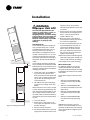
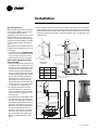
1 Secure the door frame to the side
studs using the holes located in the
door frame and field provided
screws, Figure 6.
3 After verifying that the air panel gasket is sealed to the coil, secure the
air panel to the door frame using the
slots located on the sides of the air
panel, Figure 8.
Chassis Installation
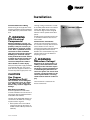
1 Remove three 16-inch bolts on the
chassis and discard, Figure 9.
Figure 9: Shipping bolts
2 Rotate the triangular metal plate to
cover the bolt holes in the chassis.
Secure with two sheet metal screws.
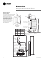
Figure 6: Door opening
Note: If the gap between the door
frame, and the side stud is over 1/16inch, place a shim in between the door
frame and the stud to prevent the door
frame from bending/denting.
2 Place the air panel into the door
opening. The gasket on the back
side of the air panel should seal
around the coil perimeter, Figure 7.
Figure 7: Air panel gasket
Figure 8: Secure to door frame
4 Install Filter.
5 Vacuum all dust and construction
debris from unit after cutting out
supply/return openings.
Supply Air Ductwork
1 A 2" (50.8 mm) duct flange (field
provided) may be required to help
eliminate supply air from recirculating back into the return air, air-to-refrigerant coil prior to discharging
into the space.
2 Equipment containing a top discharge, ducted design: install field
ductwork to the unit providing a water tight flexible connector at the
unit. This helps prevent operating
sounds from transmitting through
the ductwork. Elbows with turning
vanes or splitters are recommended
to minimize air noise due to turbulence and to help reduce static pressure.
3 Remove two shipping brackets (one
on each side) attached to the chassis
slide rails and discard, Figure 10.
Note: Remove this bracket only if
the enhanced sound package design
is preferred.
Figure 10: Bracket removal for
enhanced sound package
4 Connect water coil pipe to the system riser with a flexible steel hose
assembly.
5 Verify that the shut-off/balancing
valve in the return line/supply line
are closed.
6 Place shut-off valves in appropriate
location (see sticker on the equipment for best placement recommendation) to allow chassis to slide
easily in/out of unit cabinetry.
WSHP-SVN08B-EN
13