1
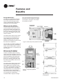
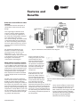
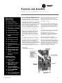
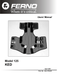
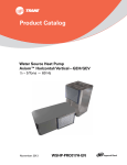
High Efficiency
Horizontal and Vertical
Water-Source Comfort System
AxiomTM
1/2 - 20 Tons - 50 Hz - Vertical (Model GEV)
1/2 - 12-1/2 Tons - 50 Hz - Horizontal (Model GEH)
WSHP-PRC003-EN
R
Introduction
Imagine a full range of comfort utilizing
efficiency, sound attenuation, integrated
controls and superior maintenance
accessibility... Trane imagined it,
designed it and built it. The AxiomTM line
of vertical and horizontal water source
heat pumps help create an advanced
comfort system for comfort solutions.
The entire range of Axiom units - 1/2ton to 20 tons - is designed with the
highest standards in mind: Ease of
maintenance; Indoor air quality; Quieter
operation and higher efficiencies. And,
all unit are rated in accordance to ARIISO 13256-1 performance and ASHRAE
90.1 standards.
With several size options, the Axiom
line of water-source heat pumps is perfect for small to medium sized office
Co-axial heat
exchanger
Thermal expansion valve
Fan/Blower
section
buildings; schools; manufacturing facilities; health care facilities; condominiums and just about any other light
commercial application.
The following is a list of design
improvements contained within all
Axiom units:
1 Maximum return/supply air
options
6 Integrated controls
7 Dual circuit design
8 High and low pressure safeties in
all units
9 Dehumidification options
10 Waterside economizer option
11 Supplimental electric heat options
2 Superior maintenance accessibility
3 Dual-sloped, plastic drain pan
4 Multiple fan speed motor
packages
12 Orifice ring motor mounting
device on all 5-ton and smaller
units
13 Internal air-to-refrigerant coil
(1/2-5-ton horizontals)
5 Quieter unit design
Integrated
controls
Model 180 GEV
Water
Connections
Model 120 GEH
Dual
Compressor
4 & 12
Model 012 GEH
2
WSHP-PRC003-EN
R
Contents
Introduction
2
Model Number Descriptiom
4
General Data
5
Features and Benefits
Options
10
Controls
17
Application Considerations
25
Performance Data
29
Electrical Performance
29
Cool and Heat Performance - English
30
Correction Factors - English
72
Cool and Heat Performance - Metric
75
Correction Factors - Metric
117
Fan Performance - English/Metric
120
Sound Data
134
Control Wiring
135
Dimensional Data
143
Accessories
171
Thermostats and Zone Sensors
180
Options
181
Mechanical Specifications
WSHP-PRC003-EN
10
185
3
R
Model Number
Horizontal/Vertical Water-Source Confort System
G E H B 036 9 1 D 0 1 1 0 D L D 0 1 0 N 0 0 1 1 0 0 0 1 0 0 0 0 0 0 0
5
10
DIGITS 1-3: UNIT CONFIGURATION
GEH = High Efficiency Horizontal
GEV = High Efficiency Vertical
DIGIT 4: DEVELOPMENT
SEQUENCE B
DIGITS 5-7: NOMINAL CAPACITY
006 = 1/2 Ton
072 = 6 Ton
009 = 3/4 Ton
090 = 7-1/2 Ton
012 = 1 Ton
120 = 10 Ton
015 = 1 1/4 Ton
150 = 12-1/2 Ton
018 = 1 1/2 Ton
180 = 15 Ton
024 = 2 Ton
240 = 20 Ton
030 = 2 1/2 Ton
036 = 3 Ton
042 = 3 1/2 Ton
DIGIT 8: VOLTAGE (Volts/Hz/Phase)
6 = 220-240/50/1
9 = 380-415/50/3
DIGITS 9: HEAT EXCHANGER
1 = Copper-Water Coil
2 = Cupro-Nickel Water Coil
DIGIT 10: CURRENT DESIGN
SEQUENCE
DIGIT 11: REFRIGERATION
CIRCUIT
0 = Heating and Cooling Circuit
2 = Heating and Cooling Circuit
with Hot Gas Reheat
3 = Heating and Cooling Circuit
with Waterside Economizer
4 = Heating and Cooling Circuit
with HGR and WSE
A = Cooling ONLY Circuit
C = Cooling ONLY Circuit
with Hot Gas Reheat
D = Cooling ONLY Circuit
with Waterside Economizer
E = Cooling ONLY Circuit
with HGR and WSE
DIGIT 12: BLOWER
CONFIGURATION
1 = Standard Blower Motor
2 = High Static Blower Motor
A = Drive Package A (GEH/GEV)
B = Drive Package B (GEH/GEV)
4
15
20
C = Drive Package C (GEH/GEV)
D = Drive Package D (GEH/GEV)
E = Drive Package E (GEH/GEV)
F = Drive Package F (GEH/GEV)
G = Drive Package G (GEH/GEV)
H = Drive Package H (GEH/GEV)
J = Drive Package J (GEV)
DIGIT 13: CUSTOMER CHANNEL
1 = Boiler/Tower Design for Trane
Commercial Group
2 = Geothermal Design for Trane
Commercial Group
5 = Trane International Group
DIGIT 14: OPEN DIGIT
0 = Standard Design
DIGIT 15: SUPPLY-AIR
ARRANGEMENT
B = Back Supply-Air Arrangement
F = Front Supply-Air Arrangement
L = Left Supply-Air Arrangement
R = Right Supply-Air Arrangement
T = Top Supply-Air Arrangement
DIGIT 16: RETURN-AIR
ARRANGEMENT
L = Left Return-Air Arrangement
R = Right Return-Air Arrangement
B = Back Return-Air Arrangement
F = Front Return-Air Arrangement
DIGIT 17: CONTROL TYPES
0 = Basic 24 V Controls
D = Deluxe 24 V Controls
C = Tracer ZN510 Controls
B = Tracer ZN524 Controls
DIGITS 18: TSTAT/SENSOR
LOCATION
0 = Wall Mounted Location
DIGITS 19: FAULT SENSORS
0 = No Fault Sensor
1 = Condensate Overflow Sensor
2 = Filter Maintenance Timer
3 = Condensate Overflow and Filter
Maitenance Timer
4 = Fan Status Sensor
6 = Condensate Overflow and Fan
Status
25
30
H = Fan Status and Filter
Maintenance Timer
J = Fan Status, Filter Maintenance
Timer and Condensate Overflow Sensor
DIGITS 20: TEMPERATURE SENSOR
0 = No Additional Temperature
Sensor
1 = Entering Water Sensor
DIGITS 21: NIGHT SETBACK
CONTROL
0 = No Night Setback Relay
N = Night Setback Relay
DIGITS 22: ELECTRIC HEAT
0 = No Electric Heat
1 = Internal Boilerless Electric Heat
DIGITS 23: UNIT MOUNTED
DISCONNECT
0 = No Unit Mounted Disconnect
DIGITS 24: FILTER TYPE
0 = 1" Filter; No Duct Flange
1 = 1" Throwaway Filter
2 = 2" Throwaway Filter
DIGITS 25: ACOUSTIC
ARRANGEMENT
0 = Enhanced Sound Attenuation
1 = Deluxe Sound Attenuation
DIGITS 26: FACTORY
CONFIGURATION
0 = Standard Factory Configuration
DIGITS 27: PAINT COLOR
0 = No Paint Selection Available
DIGITS 28: OUTSIDE AIR
0 = No Outside Air Option Available
DIGITS 29: PIPING ARRANGEMENT
0 = Standard Piping Arrangement
1 = Standard Piping with Schrader
Connection for Water Regulating Valve
DIGITS 30-36: DOES NOT APPLY TO
GEH or GEV
WSHP-PRC003-EN
R
General Data
Table G1: General Data - GEH 006 to 018
Model GEH
006
009
012
015
018
Unit Size (in/mm)
40 x 15 x 20
1016 x 381 x 508
40 x 15 x 20
1016 x 381 x 508
40 x 15 x 20
1016 x 381 x 508
46 x 17 x 23
1168 x 432 x 584
46 x 17 x 23
1168 x 432 x 584
Length x Height x Depth
Compressor Type
Rotary
Rotary
Rotary
Rotary
Reciprocating
Approx. weight
with pallet/without pallet (lbs/kg)
188 / 158
85.3 / 71.7
188 / 158
85.3 / 71.7
188 / 158
85.3 / 71.7
188 / 158
85.3 / 71.7
278 / 248
126.1 / 112.5
Filter Size (nominal in/mm)
14-5/8 x 20-1/4
375 x 517
14-5/8 x 20-1/4
375 x 517
14-5/8 x 20-1/4
375 x 517
14-5/8 x 20-1/4
425 x 603
16-3/8 x 23-5/8
425 x 603
Blower Wheel (in/mm) (Direct Drive)
9x4
229 x 102
9x4
229 x 102
9x4
229 x 102
9x4
229 x 102
9x6
229 x 152
Water in/out (FPT) (in/mm)
1/2 / 12.5
1/2 / 12.5
1/2 / 12.5
1/2 / 12.5
3/4 / 19
Condensate size (NPTI) (in/mm)
3/4 / 19
3/4 / 19
3/4 / 19
3/4 / 19
3/4 / 19
Table G2: General Data - GEH 024 to 048
Model GEH
024
030
036
042
048
Unit Size (in/mm)
Length x Height x Depth
46 x 17 x 23
1168 x 381 x 508
46 x 17 x 23
1168 x 381 x 508
50 x 19 x 25
1270 x 483 x 635
50 x 19 x 25
1270 x 483 x 635
58 x 21 x 33
1473 x 533 x 838
Compressor Type
Reciprocating
Reciprocating
Reciprocating
Reciprocating
Reciprocating
Approx. weight
with pallet/without pallet (lbs/kg)
278 / 248
126.1 / 112.5
278 / 248
126.1 / 112.5
318 / 288
144.2 / 130.6
318 / 288
144.2 / 130.6
428 / 398
184.1 / 180.5
Filter Size (nominal in/mm)
16-3/8 x 23-5/8
425 x 603
16-3/8 x 23-5/8
425 x 603
18-5/8 x 25-3/8
476 x 647
18-5/8 x 25-3/8
476 x 647
20-5/8 x 29-3/4
524 x 756
Blower Wheel (in/mm) (Direct Drive)
10 x 6
254 x 102
10 x 6
254 x 102
12 x 8
305 x 203
12 x 8
305 x 203
12 x 11
305 x 279
Water in/out (FPT) (in/mm)
3/4 / 19
3/4 / 19
3/4 / 19
1.0 / 25
1.0 / 25
Condensate size (NPTI) (in/mm)
3/4 / 19
3/4 / 19
3/4 / 19
3/4 / 19
3/4 / 19
072
090
120
150
Table G3: General Data - GEH 060 to 150
Model GEH
060
Unit Size (in/mm)
Length x Height x Depth
58 x 21 x 33
1473 x 533 x 838
Compressor Type
Scroll
Reciprocating
Reciprocating
Scroll
Scroll
Approx. weight
with pallet/without pallet (lbs/kg)
428 / 398
184.1 / 180.5
701 / 652
318.2 / 296
714 / 666
324.1 / 302.3
831 / 798
377 / 362.2
907 / 865
411.7 / 392.7
Filter Size (nominal in/mm)
20-5/8 x 29-3/4
524 x 756
Blower Wheel (in/mm) (Direct Drive)
12 x 11
305 x 279
12.6 x 12.6
321 x 321
12.6 x 12.6
321 x 321
12.6 x 12.6
321 x 321
15 x 15
381 x 381
Water in/out (FPT) (in/mm)
1.0 / 25
1-1/4 / 31.8
1-1/2 / 38.1
1-1/2 / 38.1
1-1/2 / 38.1
Condensate size (NPTI) (in/mm)
3/4 / 19
3/4 / 19
3/4 / 19
3/4 / 19
3/4 / 19
WSHP-PRC003-EN
40-3/4 x 21x 79
40-3/4 x 21x 79
40-3/4 x 21x 79
1035 x 533 x 2006 1035 x 533 x 2006 1035 x 533 x 2006
46-3/4x28x85
1187 x 711 x 2159
19-5/8 x 24-5/8 (x2) 19-5/8 x 24-5/8 (x2) 19-5/8 x 24-5/8 (x2) 24-5/8 x 24-5/8 (x3)
498 x 651
498 x 651
498 x 651
651 x 651
5
R
General Data
Table G4: General Data - GEV 006 to 018
006
Model GEV
Unit Size (in/mm)
Length x Height x Depth
009
012
015
018
21-1/2x31-1/4x19-1/5 21-1/2x31-1/4x19-1/5 21-1/2x31-1/4x19-1/5 21-1/2x31-1/4x19-1/5 21-1/2x38-1/4x21-1/2
546 x 793 x 495
546 x 793 x 495
546 x 793 x 495
546 x 793 x 495
546 x 997 x 546
Compressor Type
Rotary
Rotary
Rotary
Rotary
Reciprocating
Approx. weight
with pallet/without pallet (lbs/kg)
188 / 158
85 / 71
188 / 158
85 / 71
188 / 158
85 / 71
188 / 158
85 / 71
278 / 248
121 / 112
Filter Size (nominal in/mm)
15-7/8 x 19-7/8
403 x 505
15-7/8 x 19-7/8
403 x 505
15-7/8 x 19-7/8
403 x 505
15-7/8 x 19-7/8
403 x 505
17-7/8 x 24-7/8
454 x 632
Blower Wheel (in/mm)
(Direct Drive)
9x4
229 x 102
9x4
229 x 102
9x4
229 x 102
9x4
229 x 102
9x6
229 x 152
Water in/out (FPT) (in/mm)
1/2 / 12.5
1/2 / 12.5
1/2 / 12.5
1/2 / 12.5
3/4 / 19
Condensate size (NPTI) (in/mm)
3/4 / 19
3/4 / 19
3/4 / 19
3/4 / 19
3/4 / 19
030
036
040
Table G5: General Data - GEV 024 to 048
024
Model GEV
Unit Size (in/mm)
Length x Height x Depth
042
21-1/2x38-1/4x21-1/2 21-1/2x38-1/4x21-1/2 26-1/2x41-7/8x24-1/2 21-1/2x38-1/4x21-1/2 26-1/2x41-7/8x24-1/2
546 x 997 x 546
546 x 997 x 546
673 x 1063 x 622
546 x 997 x 546
673 x 1063 x 622
Compressor Type
Reciprocating
Reciprocating
Reciprocating
Reciprocating
Reciprocating
Approx. weight
with pallet/without pallet (lbs/kg)
268 / 248
121 / 112
268 / 248
121 / 112
308 / 288
94 / 131
268 / 248
121 / 112
308 / 288
94 / 131
Filter Size (nominal in/mm)
17-7/8 x 24-7/8
454 x 632
17-7/8 x 24-7/8
454 x 632
19-7/8 x 24-7/8
505 x 632
17-7/8 x 24-7/8
454 x 632
19-7/8 x 24-7/8
505 x 632
Blower Wheel (in/mm)
(Direct Drive)
10 x 6
254 x 102
10 x 6
254 x 102
10 x 6
254 x 102
10 x 6
254 x 102
12 x 8
305 x 203
Water in/out (FPT) (in/mm)
3/4 / 19
3/4 / 19
3/4 / 19
3/4 / 19
3/4 / 19
Condensate size (NPTI) (in/mm)
3/4 / 19
3/4 / 19
3/4 / 19
3/4 / 19
3/4 / 19
Table G6: General Data - GEV 048 to 060
6
Model GEV
048
060
Unit Size (in/mm)
Length x Height x Depth
30-1/2x46-7/8x26-1/2
774 x 1191 x 673
30-1/2x46-7/8x26-1/2
774 x 1191 x 673
Compressor Type
Reciprocating
Scroll
Approx. weight
with pallet/without pallet (lbs/kg)
396 / 348
178 / 158
396 / 348
178 / 158
Filter Size (nominal in/mm)
27-7/8 x 29-7/8
708 x 759
27-7/8 x 29-7/8
708 x 759
Blower Wheel (in/mm) (Direct Drive)
10 x 10 (DD - Std) / 254 x 254
12 x 11 (Hi) / 305 x 279
12 x 11 (Std) / 305 x 279
Water in/out (FPT) (in/mm)
1 / 25
1 / 25
Condensate size (NPTI) (in/mm)
3/4 / 19
3/4 / 19
WSHP-PRC003-EN
R
General Data
Table G7: General Data - GEV 072 to 180
Model GEV
072
090
120
150
180
Unit Size (in/mm)
Length x Height x Depth
42 x 62-5/8 x 36-1/4
1067 x 1591 x 921
42 x 62-5/8 x 36-1/4
1067 x 1591 x 921
Compressor Type
Reciprocating (2)
Reciprocating (2)
Scroll (2)
Scroll (2)
Scroll (2)
Approx. weight
with pallet/without pallet (lbs/kg)
617 / 577
280 / 262
648 / 608
294 / 276
861 / 821
391 / 373
1215 / 1170
552 / 531
1225 / 1180
556 / 536
Filter Size (nominal in/mm)
19-5/8 x 19-5/8 (4)
498 x 498 (4)
19-5/8 x 19-5/8 (4)
498 x 498 (4)
19-5/8 x 19-5/8 (4)
498 x 498 (4)
19-5/8 x 24-5/8 (6)
498 x 625 (6)
19-5/8 x 24-5/8 (6)
498 x 625 (6)
Blower Wheel (in/mm)
(Direct Drive)
12.625 x 12.625
321 x 321
12.625 x 12.625
321 x 321
12.625 x 12.625
321 x 321
15 x 15
381 x 381
15 x 15
381 x 381
Water in/out (FPT) (in/mm)
1-1/4 / 32
1-1/4 / 32
1-1/2 / 38
1-1/2 / 38
1-1/2 / 38
Condensate size (NPTI) (in/mm)
3/4 / 19
3/4 / 19
3/4 / 19
3/4 / 19
3/4 / 19
42 x 62-5/8 x 36-1/4 81-5/8 x 68 x 36-1/4 81-5/8 x 68 x 36-1/4
1067 x 1591 x 921
2073 x 1727 x 921 2073 x 1727 x 921
Table G8: General Data - GEH 240
Model GEH
240
Unit Size (in/mm)
Length x Height x Depth
81-5/8 x 68 x 36-1/4
2073 x 1727 x 921
Compressor Type
Scroll (2)
Approx. weight
with pallet/without pallet (lbs/kg)
1615 / 1580
733 / 717
Filter Size (nominal in/mm)
19-5/8 x 24-5/8 (6)
498 x 625 (6)
Blower Wheel (in/mm) (Direct Drive)
(Regular / High Static)
15 x 11 (2) / 12.625 x 12.625 (2)
381 x 279 (2) / 321 x 321 (2)
Water in/out (FPT) (in/mm)
2 / 51
Condensate size (NPTI) (in/mm)
3/4 / 19
WSHP-PRC003-EN
7
R
General Data
Air-to-Refrigerant Coils
Table G9: GEH/GEV 006
Working Pressure
Tubes High
Tubes Deep
No. of Circuits
Finned vol. (in/mm)
(H x W x D)
Coil Surface Area (Ft2)
Fins Per Inch
Tube Material
Tube OD (in/mm)
Wall Thickness
Return Bends
Table G13: GEV 015, 018, 024, 030
425
14
2
1
14 x 16 x 1.734
356 x 406 x 44
1.56
12
Copper
3/8 / 10
0.014
Copper
Table G10: GEH/GEV 009
Working Pressure
Tubes High
Tubes Deep
No. of Circuits
Finned vol. (in/mm)
(h,w,d)
Coil Surface Area (Ft2)
Fins Per Inch
Tube Material
Tube OD (in/mm)
Wall Thickness
Return Bends
Finned vol. (in/mm)
(h,w,d)
Coil Surface Area (Ft2)
Fins Per Inch
Tube Material
Tube OD (in/mm)
Wall Thickness
Return Bends
8
Working Pressure
Tubes High
Tubes Deep
No. of Circuits
Finned vol. (in/mm)
(h,w,d)
Coil Surface Area (Ft2)
Fins Per Inch
Tube Material
Tube OD (in/mm)
Wall Thickness
Return Bends
425
18
4
6
18 x 21 x 3.464
457 x 533 x 88
2.63
12
Copper
3/8 / 10
0.014
Copper
Table G15: GEH 042, 048
425
14
3
1
14 x 16 x 2.598
356 x 406 x 66
1.56
12
Copper
3/8 / 10
0.014
Copper
Table G12: GEH 015, 018, 024
Working Pressure
Tubes High
Tubes Deep
No. of Circuits
425
21
4
4
21 x 16 x 3.464
533 x 406 x 88
2.33
12
Copper
3/8 / 10
0.014
Copper
Table G14: GEH/GEV 030, 036
425
14
3
2
14 x 16 x 2.598
356 x 406 x 66
1.56
12
Copper
3/8 / 10
0.014
Copper
Table G11: GEH/GEV 012
Working Pressure
Tubes High
Tubes Deep
No. of Circuits
Finned vol. (in/mm)
(h,w,d)
Coil Surface Area (Ft2)
Fins Per Inch
Tube Material
Tube OD (in/mm)
Wall Thickness
Return Bends
Working Pressure
Tubes High
Tubes Deep
No. of Circuits
Finned vol. (in/mm)
(h,w,d)
Coil Surface Area (Ft2)
Fins Per Inch
Tube Material
Tube OD (in/mm)
Wall Thickness
Return Bends
Working Pressure
Tubes High
Tubes Deep
No. of Circuits
Finned vol. (in/mm)
(h,w,d)
Coil Surface Area (Ft2)
Fins Per Inch
Tube Material
Tube OD (in/mm)
Wall Thickness
Return Bends
425
20
4
8
20 x 29 x 3.464
508 x 737 x 88
4.03
12
Copper
3/8 / 10
0.014
Copper
Table G16: GEV 042, 048
425
16
4
4
Working Pressure
Tubes High
Tubes Deep
No. of Circuits
16 x 19 x 3.464
406 x 483 x 88
Finned vol. (h,w,d)
2.11
12
Copper
3/8 / 10
0.014
Copper
Coil Surface Area (Ft2)
Fins Per Inch
Tube Material
Tube OD (in/mm)
Wall Thickness
Return Bends
425
24
4
8
24 x 25 x 3.464
610 x 635 x 88
4.17
12
Copper
3/8 / 10
0.014
Copper
WSHP-PRC003-EN
R
General Data
Air-to-Refrigerant Coils
Table G17: GEH/GEV 060 (2-compr. circuit)
Table G20: GEH/GEV 120 (2-compr. circuit)
Working Pressure
Tubes High
Tubes Deep
No. of Circuits
Finned vol. (in/mm)
(h,w,d)
Working Pressure
Tubes High
Tubes Deep
Coil Surface Area (Ft2)
Fins Per Inch
Tube Material
Tube OD (in/mm)
Wall Thickness
Return Bends
425
18 (GEH)/ 24 (GEV)
4
6 refrig flow paths (2X)
18 x 48 x 3.464 / 457 x 1219 x 88 (GEH)
24 x 34 x 3.464 / 609 x 864 x 88 (GEV)
6.00 (GEH)
5.67 (GEV)
14
Copper
3/8 / 10
0.014
Copper
No. of Circuits
Finned vol. (in/mm)
(h,w,d)
Coil Surface Area (Ft2)
Fins Per Inch
Tube Material
Tube OD (in/mm)
Wall Thickness
Return Bends
425
24 (GEH) / 28 (GEV)
4 (GEH) / 2 (GEV)
8 refrig flow paths-2X (GEH)
7 refrig flow paths-2X (GEV)
24 x 73 x 3.464 / 609 x 1854 x 88 (GEH)
28 x 73 x 1.734 / 711 x 1854 x 44 (GEV)
12.167 (GEH) / 14.19 (GEV)
14
Copper
3/8 / 10
0.014
Copper
Table G18: GEH/GEV 072 (2-compr. circuit)
Table G21: GEH/GEV 150/180 (2-compr. circuit)
Working Pressure
Working Pressure
Tubes High
Tubes Deep
Tubes High
Tubes Deep
No. of Circuits
Finned vol. (in/mm)
(h,w,d)
Coil Surface Area (Ft2)
Fins Per Inch
Tube Material
Tube OD (in/mm)
Wall Thickness
Return Bends
425
18 (GEH)/ 28 (GEV)
4
6 refrig flow paths-2X (GEH)
7 refrig flow paths-2X (GEV)
18 x 54 x 3.464 / 457 x 1372 x 88 (GEH)
28 x 34 x 3.464 / 711 x 864 x 88 (GEV)
6.75 (GEH) / 6.61 (GEV)
14
Copper
3/8 / 10
0.014
Copper
No. of Circuits
Finned vol. (in/mm)
(h,w,d)
Coil Surface Area (Ft2)
Fins Per Inch
Tube Material
Tube OD (in/mm)
Wall Thickness
Return Bends
425
24 (GEH) / 32 (GEV)
4 (GEH) / 3 (GEV)
8 refrig flow paths-2X (GEH)
9 refrig flow paths-2X (GEV)
24 x 73 x 3.464 / 609 x 1854 x 88 (GEH)
32 x 73 x 2.598 / 813 x 1854 x 66 (GEV)
12.167 (GEH) / 16.22 (GEV)
14
Copper
3/8 / 10
0.014
Copper
Table G19: GEH/GEV 090 (2-compr. circuit)
Table G22: GEV 240 (2-compr. circuit)
Working Pressure
425
Working Pressure
425
Tubes High
18 (GEH) / 36 (GEV)
Tubes High
36
Tubes Deep
4
Tubes Deep
No. of Circuits
Finned vol. (in/mm)
(h,w,d)
Coil Surface Area (Ft2)
9 refrig flow paths (2X)
18 x 73 x 3.464 / 457 x 1854 x 88 (GEH)
36 x 34 x 3.464 / 914 x 864 x 88 (GEV)
9.125 (GEH) / 8.50 (GEV)
No. of Circuits
Finned vol. (in/mm)
(h,w,d)
Coil Surface Area (Ft2)
4
18 refrig flow paths (2X)
36 x 73 x 3.464
914 x 1854 x 88
18.25
14
Fins Per Inch
14
Tube Material
Copper
Tube Material
Copper
Tube OD (in/mm)
3/8 / 10
Tube OD (in/mm)
3/8 / 10
Fins Per Inch
Wall Thickness
0.014
Wall Thickness
0.014
Return Bends
Copper
Return Bends
Copper
WSHP-PRC003-EN
9
R
Features and
Benefits
Design Advantages
The horizontal and vertical configuratios range in capacities from 1/2 to 5
tons. The innovative designs offers
superior field flexibility at the jobsite
along with service accessibility.
ment may be field converted through a
service kit to aid in stocking of a single
unit variation. See Figure 2 for component platform location.
GEH 1/2 to 5-Ton Cabinet
The GEH cabinet design includes a
modular platform that utilizes similar
parts and assemblies throughout the
product line. It is constructed of heavy
gauge (non-painted) galvanized metal
for maximum durability and corrosive
resistive exterior.
The cabinet front allows service access
for the controls and refrigeration circuitry. Water-in/out connection and
high/low voltage hook-up is accomplished at the 45-degree corners on the
front-side of the equipment.
Figure 1: GEH Component platform location
The unit offers six product variations of
return-air and supply-air combinations
which may be order-specific or job-site
modified. See Figure 1 component platform location.
GEV 1/2 to 5-Ton Cabinet
The vertical design, model GEV
includes a modular platform utilizing
similar parts and assemblies to the horizontal to provide a repetitious look and
feel for installation and maintenance
personnel. It is constructed of heavy
gauge (non-painted) galvanized metal
for maximum durability and corrosive
resistive exterior.
The cabinet front allows service access
for the controls and refrigeration circuitry. Water-in/out connection, drain
connection, and high/low voltage hookup is accomplished at the 45-degree
chamfered corners on the front-side of
the equipment. The vertical design
offers four product variations of returnair and supply-air combinations.
The GEV model’s supply air arrange-
10
Figure 2: Component platform
location
Figure 3 Large ton GEH air side
combinations.
WSHP-PRC003-EN
R
Features and
Benefits
GEH/GEV 6 to 20-Ton Cabinet
The GEV model is also capable of onsite modifications. With the vertical configuration, the supply-air is easily converted from a top supply-air to a back
supply-air with a service retrofit kit. The
return-air option is order specific. There
are four combinations. See Figure 5 for
the four GEV supply/reutm air options.
The cabinet design incorporates sturdy
(non painted) galvanized metal form
maximum durability and corrosive
resistive exterior. The equipment offers
superior installation flexibility with
service accessibility.
The cabinet front allows service access
for the controls. The new horizontal and
vertical design offers four product variations of return-air and supply-air combinations. All combinations are order
specific and may not be modified at the
job site. See Figure 3 for air side combinations.
Hanging the horizontal configuration is
accomplished through the robust metal
stiffeners located beneath the unit.
Optional vibration isolators are available to help decrease sound vibration
during equipment operation.
Airflow Options: 1/2 to 5 ton
The GEH model configuration may be
built to order or modified on-site to
meet unique installation requirements.
The six combinations include sameside supply and return air capabilities
for added installation flexibility. See
Figure 4 for the six field convertible
combinations.
Airflow Options: 6 to 20-ton
The 6 through 12-1/2-ton horizontal’s
airflow flexibility includes four combinations to aid in applications where the
equipment is required to hug a corridor
or wall. See Figure 3 for the four vertical configurations (previous page).
Figure 5: Four GEV airflow
combinations
The sleek, narrow cabinet of the 6 to
20-ton vertical is designed to fit through
a standard doorway for installation during new or retrofit construction.The
equipment is available in four supplyair/return-air combinations. These combinations are order specific via the unit
model number. See Figure 6 for the
four vertidcal airflowvcombinations.
Figure 6: Four large-ton GEV airflow
combinations
Unit Front
Unit Front
Unit Front
Unit Front
Unit Front
Unit Front
Figure 4: Six field convertible
GEH airflow combinations
Supply Air
Return Air
WSHP-PRC003-EN
11
R
Features and
Benefits
Hanging Device: 1/2 to 5-ton
Drain Pan
The hanging bracket resides in the
chamfered corner of the horizontal 1/2 to
5 ton equipment. This partially-concealed
bracket design eliminates added height,
width, or length to the product. The
brackets are factory mounted to shorten
job installation requirements.
The unit drain pan is composed of plastic, corrosive resistive material. The pan
is positively sloped to comply with
ASHRAE 62 for (IAQ) indoor air quality
conformity. See Figure 9 to view the
plastic drain pan.
Cabinet Insulation
The structural integrity of the design
helps assure no bracket deflection or
unit bowing from the unit’s weight.
Field return-air hook-up and filter maintenance are more simplistic. Isolation for
the hanging bracket is provided with a
neoprene rubber grommet design. This
isolation device helps prevent sound
vibration from reaching the structural
support members of the building during
compressor start and stop. See Figure 7
for isolation device.
Hanging Device: 6 to 12-1/2-ton
The hanging channel for the horizontal
unit runs the length of the equipment.
The structural integrity of the design
helps assure no bracket deflection or
unit bowing from the unit’s weight.
Optional isolation for the hanging bracket is provided with a itrile rubber grommet design. This isolation device helps
prevent sound vibration from reaching
the structural support members of the
building during compressor start and
stop.
Access Panels: 12-1/2 to 20-ton
The upper panels of the 12 1/2 through
20-ton verticals feature a key hole hanging design for ease of maintenance of
the unit, allowing the panel to be hooked
into place when attaching the panel to
the unit. The panels are also sealed with
a rubber gasket at all four edges to help
eliminate air from escaping around the
panel’s edge. See Figure 8 for GEV panel
design.
All model cabinet insulation design
meets UL 181 requirements. The air
stream surface of the insulation is fabricated of a non-biodegradable source.
Figure 7: Hanging bracket design
Refrigeration Piping
The unit’s copper tubing is created from
a 99% pure copper formation that conforms to the American Society of Testing
(ASTM) B743 for seamless, lightannealed processing.
The unit’s copper refrigeration system is
designed to be free from contaminants
and conditions such as drilling fragments, dirt, or oil. This excludes the possibility of these contaminants from damaging the compressor motor.
Figure 8: Large ton GEV panel design
Compressor: 1/2 to 5-ton
The unit’s design includes a wide variety
of compressor motors to accommodate
dedicated voltages and tonnage sizes.
For more details, See General Data
Tables, pages 5-7.
Figure 9: Plastic drain pan
Figure 10: Reciprocating compressor
12
WSHP-PRC003-EN
R
Features and
Benefits
Schrader Connections:
1/2 to 5-ton
The connections for the low and high
side of the refrigeration system are
located directly beside the control box at
the front, service access panel. See
Figure 11 for schrader connection lotion.
Co-axial Water-to-Refrigerant
Coil
Figure 11: Schrader connections
Figure 12: Water connections - small
ton
The unit’s internal heat exchanging
water coil is engineered for maximum
heat transfer.
The copper or cupro-nickel seamless
tubing is a tube within a tube design.
The inner-water tube contains a deep
fluted curve to enhance heat transfer
and minimize fouling and scaling. It is
available in either copper or cupro-nickel
(selectable option) coil.The outer refrigerant gas tube is made from steel material. The coil is leak tested to assure there
is no cross leakage between the water
tube and the refrigerant gas (steel tube)
coil. Co-axial heat exchangers are more
tolerant to freeze rupture. See Figure 11
for co-axial water coil.
Compressor and Co-axial Coil
Isolation: 1/2 to 5 ton
Figure 13: Water connections - large
ton
Vibration isolation of the compressor
and co-axial water coil is accomplished
by increasing the rigidity and stiffness at
the base. The platform provides double
isolation to the compressor and single
isolation to the co-axial water coil for
additional attenuation during compressor start and stop.
Water Connections: 1/2 to 5-ton
The water-in/water-out connections to
the co-axial water coil are located on the
right-hand chamfered corner of the unit.
The fittings are mounted flush to the
chamfered wall to help limit shipping
damage.
Figure 14: Thermal expansion valve
WSHP-PRC003-EN
The water connection devices are constructed of copper or bronze material
and include a National Female Pipe
Thread (NFPT) junction. The connections
are attached to the unit’s chamfer corner
to alleviate the need for a back-up
wrench during installation. See Figure 12
for water connection device.
Water Connections: 6 to 20-ton
Water hookups for the 6 through 20 ton
units are located internal to the equipment to help alleviate damage to the
water copper during shipment or job
storage of units prior to installation.
Each unit (although dual circuited) contains a single supply and return water
connection. See Figure 13 for large tonnage water hook-up, model GEV. Fittings
for the supply and return are internally
threaded.
Expansion Valve
All Trane water-source systems include
an expansion valve flow metering
device. This thermal expansion valve
(TXV) allows the unit to operate with an
entering fluid temperature from 25 F (3.9
C) to 110 F (43 C), and entering air temperatures from 40 F (4.4 C) to 90 F (32 C).
The valve is designed to meter refrigerant flow through the circuitry to achieve
desired heating or cooling.
The expansion valve device allows the
exact amount of refrigerant required to
meet the coil load demands. This precise
metering by the TXV increases the efficiency of the unit.
Reversing Valve
A system reversing valve (4-way valve)
is included with all heating/cooling units.
This valve is piped to be energized in the
cooling mode to allow the system to
provide heat if valve failure were to
occur. Once the valve is energized for
cooling, it will remain energized until the
control system is turned to the OFF position, or a heating cycle is initiated.
Units with the cooling only option will
not receive a reversing valve.
13
R
Features and
Benefits
Blower Motor: 1/2 to 5 ton
The supply-air (blower) motor is a
multi-speed motor with internal thermal overload protection. The motor
bearings are permanently lubricated
and sealed.
Access to the 6 through 25 ton units is
made through the back of unit by way
of two panels, and/or through a side
access panel if adjustment to the motor
belt or motor base are needed.
Blower Housing
All motors are factory wired to the
option selected. A high, medium, and
low speed tap is provided for field customization on most voltages. The speed
tap modification can be made in the
control box of the unit. See Figure 15
for blower motor.
Note: The three-phase designs are provided in a dual or three-speed version
only. See fan performance section for
factory ratings.
Serviceability to the motor is made
through either of the two air-side
access doors for the horizontal configuration, and through one air-side access
door on vertical configuration. The
motor and blower wheel are removable
by an orifice ring mounted to the fan
housing.
Blower Motor: 6 to 20 ton
A belt driven motor selection powers
the fan for the 6 through 20 ton dual
circuit units. The 6 through 12-1/2 ton
units include a single fan assembly. The
15 and 20-ton units include dual fan
assemblies. Because the motor sheave
and the motor base are adjustable in
the field, a greater variation in external
static pressures are available.
The large tonnage units are capable of
providing 0 ESP to 3.0 ESP allowing a
higher static ductwork to be applied on
the mechanical system when the application requires extensive ductwork
design. This is a low cost alternative to
purchasing, installing, and maintaining
multiple smaller tonnage units to meet
the required air flow demand for the
space.
14
The blower housing is constructed of
non-corrosive galvanized steel. A factory-mounted orifice ring is provided for
ease of motor serviceability on the 1/2
through 5-ton direct drive units.
All air-side panels are interchangeable
with one another for ease of field convertibility of the supply-air on the GEH
model.
Figure 15: 1/2 to 5-ton blower motor
Air-Side Filter
The air-side filter incorporates severalfiberglass options. These filters include
an average synthetic dust weight
arrestance of approximately 75%. This
dust holding capability includes a colorless, odorless adhesive to retain dirt
particles within the filter media after
fiber contact.
Figure 16: 6 to 20-ton blower motor
and fan belt assembly.
Air-to-Refrigerant Coil
The air-to-refrigerant heat exchanger is
constructed of staggered copper tubes
with die-formed corrugated lanced aluminum fins. The fins are then mechanically bonded to the tubes through
expansion.
The coil is placed internal of the unit
design for the GEH model to provides
an optional dual filtration application.
With dual filtration to the GEH unit,
maintenance to the filter is significantly
less than with a single filtration system.
This design also offers maximum flexiblity of the supply and return air configurations.
The maximum working pressure for
both the GEH and GEV coils is 450 psig.
It is designed for maximum capacity
with an additional benefit of physical
unit size reduction.
WSHP-PRC003-EN
R
Features and
Benefits
Boilerless Control/Electric Heat
(option)
The boilerless electric heat option is
composed of a nichrome open wire
design.
This single stage of electric heat is
used as a primary heating package
to lock out compressor operation in
the event that entering-water temperatures reach below 58 F (14.4 C).
On a call for heating, the electric heater
is activated, locking out the compressor. Once the entering water temperature rises, above 58 F (14.4 C), the unit
resumes normal compressor heating
operation.
For geothermal applications, the
boilerless controller is adjustable.
The ranges are 25, 35, 45, 55, and
60-degrees F (-3 .9 , 1.7, 7.2, 12.8 ,
15.6 C). Trane factory sets the controller
to 55-degrees F prior to shipment.
See Figure 17 for boilerless
control/electric heat diagram.
Waterside Economizer (option)
The beauty of the waterside economizer is it’s ability to take advantage of any
loop condition that results in cool water
temperatures. A prime example would
be during fall, winter and spring when
cooling towers have more capacity
than required and could be controlled
to lower temperatures for economizer
support.
Another more common inexpensive
means of free comfort cooling includes
buildings systems where perimeter
heating and core cooling are needed. In
this system, the perimeter units extract
heat from the building loop while in the
heating mode, forcing the building loop
temperature to drop. Where as, the core
are of a building may require cooling in
summer or in winter based upon lighting, people and equipment.
WSHP-PRC003-EN
Figure 17: Boilerless control/electric heat diagram
If the water-source system
design contained an economizing coil option, the moderate temperature loop
water circulated through a
core water-source system
can provide an inexpensive
means to satisfy room comfort without operating the
water-source heat pump’s
compressor.
During economizer mode,
fluid enters the unit, and
passes by a water temperature sensing bulb. This temperature sensing bulb deterFigure 18: Model GEH with Waterside Economizer
mines whether the two posipackage
tion, three-way valve will
direct the water through the
Mechanical cooling will continue on a
waterside economizing coil, and to the
call for second stage from the thermoheat pump condenser, or through the
stat. The factory built waterside econocondenser only. If the water temperamizer is available on all 1/2 to 5 ton
ture is 55 F or less, fluid will flow into
GEH models.The 1/2 through 5-ton GEV
the economizing coil, while simultanemay be ordered to accept a field proously halting mechanical operation of
vided waterside economizing package.
the compressor.
See Figure 18: Model GEH with
Waterside Economizer package.
15
R
Features and
Benefits
Hot Gas Reheat (option)
Proper Hot Gas Design
For space conditioning and climate control, Trane provides an accurate and
cost effective dehumidification control
through a hot gas reheat option. This
option is designed to accommodate
unit sizes 012, 036, 060 and 072 through
240.
The factory installed hot gas reheat
option is only available with Deluxe or
ZN524 controls packages.
With this reheat option, the return air
from the space is conditioned by the
air-to-refrigerant coil, then reheated by
the reheat coil to control not only the
space temperature, but to also reduce
the relative humidity of the space. The
moisture removal capability of a specific heat pump is determined by the units
latent capacity rating.
When operating in the reheat mode
(meaning the sensible temperature has
been met in the space), the humidistat
signals the reheat relay coil to energize,
allowing the high pressure refrigerant
gas to flow from the (1) compressor,
through the (2) reheat valve, into the
(3) reversing valve, or through the (4)
reheat coil for dehumidification (See
Figure 19). A switching relay has been
provided for the reheat application to
adjust the blower motor from normal
operation to low speed when hot gas
reheat is energized.
Note: Trane places an air separation
space between the air-to-refrigerant
coil, and the reheat coil to allow for
maximum moisture removal.
A high static blower motor option will
be required to support the hot gas
reheat option for the 1/2 through 5 ton
equipment.
Water regulating valves should not be
used with the hot gas reheat option.
Trane places a thermal expansion valve
on all water-source heat pumps, as well
as ground-source heat pumps, to regulate refrigerant flow vs. water flow,
making the heat pump more efficient to
run.
Water-source heat pumps with hot gas
reheat should not be used as a makeup air unit.
Common Reheat Applications
The hot gas reheat option is designed
to support building applications requiring fresh-air ventilation units delivering
unconditioned-air directly to the space.
It also provides dehumidification to
large latent load spaces such as auditoriums, theaters and classrooms, or anywhere humidity control is a problem.
Figure 19: Hot gas reheat heat pump option.
16
WSHP-PRC003-EN
R
Features and Benefits
Controls
Controls by Trane
Whether involved in a retrofit or new construction application, Trane has the control design to fit your system requirement.
Our control options provide a broad range of packages from the most cost efficient 24 volt standalone to a complete building
automation solution, Trane is the right choice in comfort gratification. The following chart provides a brief overview in the different control combinations.
Control
Basic 24V
Graphic
Description
Compressor lockout relay, low
and high pressure switches.
Deluxe 24V
24 volt microprocessor
designed to provide control of
the entire unit, as well as multiple relay offerings to maximize
system performance. Can connect to a 24V thermostat.
Tracer ZN510TM
Direct Digital Control board
designed to provide control of
the entire unit as well as outputs for unit status and fault
detection.
Tracer ZN524TM
TracerTM Loop
Controller
TrackerTM
Direct Digital Control board
designed to provide control of
the entire unit as well as outputs for unit status and fault
detection.
Microprocessor-based
controller that coordinates the
water side (boiler, pumps, cooling tower, etc.) of a watersource heat pump system.
Microprocessor-based
controller that coordinates boiler, pumps, cooling tower, etc.
of a water-source heat pump
system. Customized alarms,
scheduling, trending, safety
features.
Controls up to 100 wshp’s.
Tracer
Summit®
WSHP-PRC003-EN
Microprocessor based
controller that coordinates full
building automation from
HVAC to lighting.
Application
ICS
Protocol
No
NonApplicable
No
NonApplicable
Yes
SCC LonTalk®
open protocal
(Comm 5)
Yes
SCC LonTalk®
open protocal
(Comm 5)
Yes
LonTalk
compatible
(Comm 5)
Yes
LonTalk
compatible
(Comm 5)
Yes
BACnet
(Comm 2, 3, 4,
& 5)
Retrofit market where single and
multiple unit replacement occurs.
New building design where field
provided controls are specified.
Retrofit market where single and
multiple unit replacement occurs.
Multi-unit installation where units
may be daisy- chained directly to
the Trane TracerTM Loop Controller.
Retrofit market where overall system upgrade is specified.
Multi-unit (100+) installation where
units are linked by a common twisted pair of wire for a communication
link.
Retrofit market where overall system upgrade is specified.
Multi-unit (100+) installation where
units are linked by a common twisted pair of wire for a communication
link.
Wherever the Tracer ZN510 controls
or 24 volt electro-mechanical
controls are specified for complete
control of the water loop and
pumps.
Wherever the Tracer ZN510 controls
or 24 volt electro-mechanical
controls are specified for complete
control of the water loop and
pumps.
New and retro fit light commercial
applications.
Where any controller is specified.
17
R
Features and Benefits
Basic Controls
Basic 24 Volt Controls
The basic 24 V electromechanical unit
control provides component protection
devices for maximum system reliability.
Each device is factory mounted, wired
and tested. See Figure 20 for the unit
control box.
excessive discharge pressures that
exceed 395 psig.
A lockout relay provides the mechanical
communication of the low and high
pressure switches to prevent compressor operation if the unit is under low or
high refrigerant circuit pressure, or during a condensate overflow condition.
The lockout relay may be reset at the
thermostat, or by cycling power to the
unit.
General alarm is accomplished through
the lockout relay and is used in driving
light emitting diodes. This feature will
drive dry contacts only, and cannot be
used to drive field installed control
inputs. See Figure 21 for unit safety
devices on the basic 24V control unit.
Figure 20: Basic 24-volt control box.
Stand-alone System
Figure 21: BAsic 24-volt safety devices.
Safety Devices
System safety devices are provided
through the use of low/high pressure
switches in the refrigeration circuit to
help prevent compressor damage. The
switch and sensor are set to activate at
refrigerant pressures of 20 psig to fit
most applications.
Figure 22: 24-volt stand-alone system.
In cases where a low charge, or excessive loss of charge occurs, each compressor comes equipped with an external overload device to halt the compressor operation.
The high pressure switch prevents
compressor operation during high or
18
The 24 volt electro-mechanical design
may be applied as a stand-alone control system. The stand-alone design
provides accurate temperature control
directly through a wall-mounted mercury bulb or electronic thermostat. This
system set-up may be utilized in a
replacement design where a single unit
retrofit is needed. It may be easily interfaced with a field provided control system by way of the factory installed 18pole terminal strip.
This stand-alone control is frequently
utilized on small jobs where a building
controller may not be necessary, or
where field installed direct digital controls are specified. This type of control
design does require a constant flow of
water to the water source heat pump.
With a positive way to sense flow to
the unit, the units safety devices will
trigger the unit off.
The stand-alone system design provides a low cost option of installation
while still allowing room control for
each unit. See Figure 22 for 24 volt
stand-alone system controls.
WSHP-PRC003-EN
R
Features and Benefits
Deluxe Controls
Deluxe 24V Electronic Controls
The deluxe 24V electronic unit control
provides component protection devices
similar to the basic design, but contains
upgraded features to maximize system
performance to extend the system life.
Each device, is factory mounted, wired,
and tested in the unit. See Figure 23 for
unit control box.
Small Building Control
The deluxe 24V electro-mechanical
design may be applied as a stand-alone
control system or as a multi-unit installation system. With a stand-alone
design, units run independently of one
another with a mercury bulb or electronic digital thermostat.
With a multiple unit installation, the
units may be daisy-chained directly to
the Trane Tracer loop controller (TLC),
pump(s), boiler, and tower for a complete networked water-source system.
The TLC provides a night setback output, and a pump request input for system optimization.See Figure 24 for 24volt deluxe control system.
Figure 23: Deluxe 24V control box.
Figure 24: 24-volt deluxe control
system.
WSHP-PRC003-EN
19
R
Features and Benefits
Deluxe Controls
Microprocessor Design
The 24 volt deluxe design is a microprocessor-based control board conveniently located in the control box. The
board is unique to Trane water-source
products and is designed to control the
unit as well as provide outputs for unit
status and fault detection.
The Trane microprocessor board is factory wired to a terminal strip to provide
all necessary terminals for field connections. See Figure 27 for the deluxe 24V
control board.
Deluxe 24V features include:
Random Start
The random start relay provides a time
delay start-up of the compressor when
cycling in the occupied mode. A new
start delay time between 3 and 10 seconds is applied each time power is
enabled to the unit.
Anti-short Cycle Timer
The anti-short cycle timer provides a
three minute time delay between compressor stop and compressor restart.
Brown-out Protection
The brown-out protection function
measures the input voltage to the controller and halts the compressor operation. Once a brown-out situation has
occurred, the anti-short cycle timer will
become energized. The general fault
contact will not be affected by this condition. The voltage will continue to be
monitored until the voltage increases.
The compressors will be enabled at this
time if all start-up time delays have
expired, and all safeties have been satisfied.
Compressor Disable
The compressor disable relay provides
a temporary disable in compressor
operation. The signal would be provided from a water loop controller in the
system. It would disable the compres-
20
sor because of low water flow, peak
limiting or if the unit goes into an unoccupied state. Once the compressor has
been disabled, the anti-short cycle time
period will begin. Once the compressor
disable signal is no longer present, and
all safeties are satisfied, the control will
allow the compressor to restart.
Generic Relay
The generic relay is provided for field
use. Night setback or pump restart are
two options that may be wired to the
available relay. (Note: Night setback is
available as factory wired). An external
Class II 24VAC signal will energize the
relay coil on terminals R1 and R2.
Terminals C (common), NO (normally
open), and NC (normally closed) will be
provided for the relay contacts.
Safety Control
The deluxe microprocessor receives
separate input signals from the refrigerant high pressure switch, low suction
pressure switch and condensate overflow.
In a high pressure situation, the compressor contactor is de-energized,
which suspends compressor operation.
The control will go into soft lockout
mode initializing a three minute time
delay and a random start of 3 to 10 second time delays. Once these delays
have expired, the unit
will be allowed to run.
If a high pressure situation occurs within one
hour of the first situation, the control will be
placed into a manual
lockout mode, halting
compressor operation,
and initiating the general alarm.
switch is open for 45 seconds during
compressor start, the unit will go into
soft lockout mode initializing a three
minute time delay and a random start
of 3 to 10 second time delays. Once
these delays have expired, the unit will
be allowed to run. If the low pressure
situation occurs again within 30 minutes, and the device is open for more
than 45 seconds, the control will be
placed into a manual lockout mode,
halting compressor operation, and initiating the general alarm.
In a condensate overflow situation, the
control will go into manual lockout
mode, halting compressor operation,
and initiating the general alarm.
The general alarm is initiated when the
control goes into a manual lockout
mode for either high pressure, low
pressure or condensate overflow conditions.
Diagnostics
Component device connections to the
microprocessor board are referenced in
Figure 25. Three LEDs (light emitting
diodes) are provided for indicating the
operating mode of the controller. See
the unit IOM for diagnostics or troubleshooting through the use of the
LEDs.
Figure 25:
Deluxe 24V
control
board.
In a low temperature
situation, the low pressure switch will transition open after the compressor starts. If the
WSHP-PRC003-EN
R
Features and Benefits
ZN510 & ZN524 Controls
Tracer ZN510 & ZN524 Controls
The Tracer ZN510 and ZN524 are direct
digital control (DDC) systems specifically designed for single and dual circuited
water-source equipment to provide control of the entire unit, as well as outputs
for unit status and fault detection. Each
device is factory installed, commissioned, and tested to ensure the highest level of quality in unit design.
Each of the controller’s features and
options were selected to coordinate
with the unit hardware to provide
greater energy efficiency and equipment safety to prolong the equipment
life.
In addition to being factory configured
for control of the unit fan, compressor
and reversing valve, the ZN510 and
ZN524 controllers are designed to coordinate the waterside of the water-source
system through the Tracer Loop
Controller (TLC). If applied in a peer-to-
peer communication environment, data
between similar controllers may be
exchanged without requiring a building
automation system.
By teaming the ZN510 and ZN524 with
the TLC, a low first-cost for the mechanical equipment, water loop, and water
pump optimization is provided to the
owner.
For owners who require a full building
integrated "open protocol" system, The
ZN510/ZN524/TLC application is
upgradable to support complete building control through Tracer Summit.
Because the ZN510 and ZN524 is
LonTalk certified, it is capable of working with, and talking to other LonTalk
certified controllers providing the building owner more choices, and the design
engineers more flexibility to meet the
challenges of building automation. See
Figure 26 for ZN510 control box.
Figure 26:
ZN510/ZN524 control box
WSHP-PRC003-EN
21
R
Features and Benefits
ZN510 & ZN524 Controls
Direct Digital Controls
When the ZN510 or ZN524 controller is
linked directly to the Tracer Summit,
each Tracer Summit building automation system can connect a maximum of
120 Tracer ZN510 or ZN524 controllers.
See Figure 27 for the Tracer ZN524
board.
Figure 27:
Tracer
ZN524
board.
Tracer ZN510 and ZN524 functions
include:
Compressor Operation
The compressor is cycled on and off to
meet heating or cooling zone demands.
Single and dual compressor units use
the unit capacity and pulse width modulation (PWM) logic along with minimum on/off timers to determine the
compressor’s operation. The compressor is controlled ON for longer periods
as capacity increases and shorter periods as capacity decreases.
Random Start
To prevent all of the units in a building
from energizing major loads at the
same time, the controller observes a
random start from 0 to 25 seconds. This
timer halts the controller until the random start time expires.
Reversing Valve Operation
For cooling, the reversing valve output
is energized simultaneously with the
compressor. It will remain energized
until the controller turns on the compressor for heating. At this time, the
reversing valve moves to a de-ener-
22
gized state. In the event of a power failure or controller OFF situation, the
reversing valve output will default to
the heating (de-energized) state.
during daytime hours of temporary low
occupancy. To determine the space
occupancy, an occupancy sensor is
applied.
Fan Operation
The supply air fan operates at the factory wired speed in the occupied or occupied standby mode. When switch is set
to AUTO, the fan is configured for
cycling ON with heating or cooling. In
heat mode, the fan will run for 30 seconds beyond compressor shutdown in
both occupied and unoccupied mode.
In an unoccupied situation, the controller assumes the building is vacant,
normally during evening hours. In the
unoccupied mode, the controller uses
the default unoccupied heating and
cooling setpoints stored in the controller. When the building is in unoccupied mode, individual units may be
manually placed into timed override of
the unoccupied mode at the units wall
sensor. During timed override, the controller interprets the request and initiates the occupied setpoint operation,
then reports the effective occupancy
mode as occupied bypass.
Fan Run Timer
The controller’s filter status is based on
the unit fan’s cumulative run hours. The
controller compares the fan run time
against an adjustable fan run hours
limit and recommends unit maintenance as required.
Data Sharing
The Tracer ZN510/ZN524 controller is
capable of sending or receiving data
(setpoints, fan request, or space temperature) to and from other controllers
on the communication link. This allows
multiple units to share a common
space temperature sensor in both
stand-alone and building automation
applications.
Night Setback
The four operations of the Tracer
ZN510/ZN524 controller include occupied, occupied standby, occupied
bypass and unoccupied.
In an occupied situation, the controller
uses occupied heating and cooling setpoints to provide heating and cooling
to the building. This occupied operation
is normally used during the daytime
hours when the building is at the highest occupancy level.
In an occupied standby situation, the
controllers heating and cooling setpoints are usually wider than the occupied setpoints. This operation is used
In the occupied bypass mode, the controller applies the occupied heating and
cooling setpoint for a 120 minute time
limit.
High/Low Pressure Safety Controls
The Tracer ZN510/ZN524 controller
detects the state of the high pressure or
low pressure switches. When a fault is
sensed, the corresponding message is
sent to the controller to be logged into
the fault log. When the circuit returns to
normal, the high pressure control and
low pressure control automatically
reset. If a second fault is detected within a thirty-minute time span, the unit
must be manually reset.
Condensate Overflow
When condensate reaches the trip
point, a condensate overflow signal
generates a diagnostic which disables
the fan, unit water valves (if present),
and compressor. The unit remains in a
halted state until the condensation
returns to a normal level. The switch in
the drain pan will then automatically
reset. The controller’s condensate overflow diagnostic must be manually reset
to clear the diagnostic and restart the
unit.
WSHP-PRC003-EN
R
Features and Benefits
ZN510 & ZN524 Controls
More ZN524 Controller Functions:
When the building owners choice is
Trane Tracer controls, the ZN524 controller is required when any of the following applications are selected on a
single and dual circuited equipment.
• Waterside Economizer
• Hot Gas Reheat (Dehumidification)
• Boilerless Control for Electric Heat
• Water Isolation Valve Control
(for Variable Speed Pumping)
Entering Water Temperature
Sampling
The ZN524 controller will sample the
entering water temperature to determine proper control action for units
equipped with boilerless electric heat or
waterside economizer.
Waterside Economizer
Entering water temperature (EWT) sampling will automatically occur at power
up when the unit is equipped with a
waterside economizer (WSE). The EWT
is used to determine if economizing is
feasible. When the conditions are met,
the isolation valve(s) are driven open
for three minutes and the EWT reading
is taken. The determination as to
whether or not the economizer can be
enabled will be made and the controller
will take appropriate action. The isolation valve will remain open regardless
if the WSE or the DX cooling is enabled.
The unit’s waterside economizer will
contain a 2-position water valve wired
to the ZN524. The economizing water
coil will be optimized to provide 100%
of the unit capacity at 80.6 F/66.2 F
(27.0/10.0 C) return air temperature with
45 F (7 C) entering water. The flow rate
is established at 86 F (30 C) entering
water temperature and 96 F (36 C) leaving water temperature.
WSHP-PRC003-EN
Low leaving air protection will be furnished to protect the unit against delivering air that is cold enough to sweat
discharge air grilles. Coil icing protection will also be provided.
Waterside economizer cooling will be
active during occupied, unoccupied and
standby cooling modes.
Boilerless Control Electric Heat and
Supplemental Electric Heat: The ZN524
supports a single stage of boilerless
electric heat operation or concurrent
heating.
When the unit is configured for boilerless control, the EWT will be used to
determine whether DX heating should
be disabled and the electric heater
enabled. When these conditions are
met, the isolation valve(s) are driven
open for three minutes and the entering water temperature reading is taken.
The determination as to whether or not
to utilize electric heat will be made and
the controller will take appropriate
action. If boilerless electric heat is
enabled, then the isolation valve will be
closed, shutting down the water flow to
the unit.
When the unit is configured for concurrent operation of DX heating (compressor in heat pump mode) and electric
heat, the electric heat will act as a second stage of heat for single compressor
units, and a third stage of heat for dual
compressor units. Note: With concurrent (or supplemental) electric heat, the
electric heater is field provided.
are driven open for operation, the outputs will be driven for 20 seconds to
ensure adequate water flow before the
compressor outputs are energized.
Once an isolation valve has been
opened, it will remain open for a 10
minute minimum to reduce excessive
cycling of the valve.
Dehumidification
Dehumidification for the single and
dual circuited water-source heat pump
is applicable with the ZN524 controller.
The controller is capable of directing
one stage of DX cooling in conjunction
with one stage of reheat (hot gas
reheat).
Dehumidification can only occur when
the controller is in the cooling mode. A
humidity transmitter is used to measure the zone’s relative humidity (RH),
then compares the zone relative humidity to the relative humidity enable/disable setpoint parameters. The default
values for dehumidification enable is
60% RH with the disable point at 52%
RH. These values are configurable.
Water Isolation Valves
Variable speed pumping systems are
supported by the ZN524 controller
when water isolation valves are present. Up to two isolation valves are supported by the controller (one for each
compressor circuit).
The valves are normally closed unless
DX heating, DX cooling, waterside
economizer or dehumidification is
requested. When the isolation valves
23
R
Features and Benefits
ZN510 & ZN524 Controls
Building Control Advantages
The Tracer ZN510/ZN524 controller has
the ability to share information with
one or several units on the same communication link. This sharing of information is made possibe via a twisted
pair of wire and a building automation
system or through Trane’s RoverTM
service tool .
An advantage of installing a
ZN510/ZN524 is its capability to work
with other LonTalk certified controllers.
This provides greater flexibility to the
building owner, as well as greater flexibility in design.
Integrating the ZN510/ZN524 on watersource equipment, and tying it to a
Tracer Summit system provides a complete building management system.
Each Tracer Summit can connect to a
maximum of 120 controllers. With the
ICS system, the Tracer can initiate an
alarm on a loss of performance on
equipment malfunctions; allowing
problems to be handled in a timely
manner before compromising comfort.
This type of application would most
commonly be used for a large space(s)
that may require more than one unit. In
addition to this application design, the
Tracer ZN510/ZN524 controller provides
a way for units located within the same
space to share the same zone sensor to
prevent units from simultaneously
heating and cooling in the same
space.See Figure 28 for Tracer
ZN510/ZN524 controller system.
Figure 28: Tracer ZN controller system installation.
24
WSHP-PRC003-EN
R
Application
Considerations
Figure 29: Horizontal unit installation
4”
1/
e:
op
l
S
.5
(6
)
m
m
12”/ 305mm
Slope: 1/4” (6.5 mm)
Hanging the Horizontal
The horizontal unit GEH A is a ceiling
hung unit. It is usually applied as a
totally concealed unit above an acoustical ceiling grid. Because the GEH A is
equipped with several inlet and discharge arrangements, it allows for
numerous application needs.
When hanging the horizontal design,
the unit should be pitched approximately 1/4-inch (6.4 mm) per foot
toward the drain in both directions.
This aids in condensate removal from
the drain pan. (See Figure 29 for unit
installation.)
Hanging Devices and Duct
Attachments
Figure 30: Unit duct collar
and hanging device
installation.
All GEHA units are shipped with a factory mounted hanging bracket and rubber isolation grommet. The 3/8 -inch
(9.5 mm) all-thread and 3/8 -inch
(9.5 mm) washer and nut are field provided.
One-inch duct collars are provided for
field duct attachment to the supply-air
outlet. The duct collars, filter racks, filter and grommets are field installed.
These items are shipped in an inclosure external to the unit. (See Figure 30
for unit duct collar and hanging device
installation.)
WSHP-PRC003-EN
25
R
Application
Considerations
Condensate Traps
When designing a condensate trap for the
water-source system, it’s important to consider
the unit’s draw through design.
Under normal conditions, condensate runs
down the coil fins and drips into a condensate
pan. In situations where no trap is installed,
the water level that would be maintained in the
trap to create a seal, backflows through the
drainline into the unit. Because the fan pulls air
through the air-torefrigerant heat-exchanger,
this incoming air stream could launch water
droplets, forming at the base of the coil, into
the air.
the mechanical system. This aerosol
mist can be carried through the ducts and into
the conditioned air space.
Another problem with air backflow, is the
source of that air. Drain lines typically flow into
waste or sewage lines, giving the potential to
introduce methane and other contaminants
from the drain system into the airstream.
In a properly trapped system, when condensate forms during normal operation, the water
level in the trap rises until there is a constant
outflow. (See Figure 31, for the appropriate
dimensions required in designing a negative
pressure system.)
Air flowing through the coil can then spray
condensate into the fan intake, with the possibility of propelling moisture into other parts of
Figure 31: Condensate trap installation.
26
WSHP-PRC003-EN
R
Application
Considerations
Distributed Pumping System
A distributed pumping system contains
either a single or dual pump module,
specifically sized for each water-source
heat pump, then connected directly to
the units supply and return lines.
The distributed system’s supply and
return lines should be sized to handle
the required flow with a minimum pressure drop.
1. Hose kits are used to connect the
water supply and return line to the
water inlets and outlets. Trane offers
various hose kit combinations to
better facilitate system flow balancing. These flexible hoses also aid in
the reduction of vibration between
the unit and the rigid central piping
system.
sized to handle the required flow with
a minimum pressure drop.
Note: Pipe will sweat if low temperature water is below the dew point of the
surrounding space. Trane recommends
that these lines be insulated to prevent
damage from condensation when condenser loop is designed to be below
60 F/ 16 C. Equipment installed in
attic/crawl space temperatures below
40 F/ 4 C may require antifreeze in the
water loop.
7. For acoustically sensitive areas, a sixinch deep fiberglass insulation is
recommended to be field installed
below the horizontal unit. This field
supplied insulation should be
approximately twice the footprint size
of the unit. It provides sound
damping of the unit while in
operation.
Figure 32: Distributed pumping system installation.
2.The unit’s (item 2) 3/4-inch high
3. voltage and (item 3) 1/2-inch low
voltage connections are located on
the left chamfered corner of the unit.
They are designed to accept conduit.
4.A field supplied line voltage
disconnect should be installed for
branch circuit protection. Check local
codes for requirements.
5.Trane’s self-contained pump module
and hose kit make a complete pumping package for distributed pumping
systems. The module is designed for
circulating commercial loops that
require a maximum flow rate of
20 gpm (76 lpm). Each pump module
is fully assembled for connection to
water and electrical points. The kit
contains all of the necessary
components for the installation,
operation and maintenance of a
closed loop application.
See WSHPC-IN-5 (72-9006-03) for
electrical and dimensional requirements
6.The distributed pumping system
supply and return lines should be
WSHP-PRC003-EN
27
R
Application
Considerations
Installation Made Easy
Installing a horizontal unit inside a corridor to enhance sound attenuation provides value to duct design. Trane takes
this fact one step further.
The new GEH design offers same side
return-air/supply-air access to the unit.
This access is contained within the
overall dimension of the units length as
shown in Figure 32. The duct access to
the unit allows the unit to be installed
closely against a corridor wall, while at
the same time eliminating space
required for the duct design.
Most horizontal unit designs provide an
opposite supply air from the return air
arrangement, or an end supply arrangement option. See Figure 33 for end-supply example. An end-supply design
increases the overall unit length of the
system to accommodate a 90-degree
duct turn. This not only requires added
space, but also adds cost in both materials and installation.
Additional value to the design is
acquired through the same side supply/return-air design. This design eliminates a requirement for a four sided
service access. When installing the
same side return/supply-air access, a
brief 3-inch minimum is all that is
required between the unit and the wall.
Service Access
To add more value in installation
requirements, the same side
supply/return design eliminates the
need for a four-sided service access
(See Figure 34). When installing the
same side return/supply access, a small
3” / 76 mm minimum space is required
between the unit and wall.
Figure 32: Same side supply/return air and end supply
arrangements with ductwork.
Figure 33: Service access requirments.
28
WSHP-PRC003-EN