1
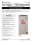
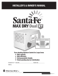
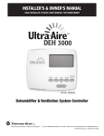
INSTALLER’S & OWNER’S MANUAL HVAC INSTALLER: PLEASE LEAVE MANUAL FOR HOMEOWNER Rx Rx Free-standing dehumidification for your home. n n Includes installation, operating and safety instructions, warranty information and all ancillary products. n Read and save these instructions. P.O. Box 8680 Madison, WI 53708 • TOLL-FREE 1-800-533-7533 • www.thermastor.com • [email protected] © 2006 Therma-Stor LLC • Manual P/N TS- 235 8/07 For small usage: TABLE OF CONTENTS Table of Contents 1. Specifications Part Number: Model: Electrical: Capacity: Operating Temp. Range: Air Flow: Refrigerant Charge: Unit Size: Weight: 1. Specifications........................................................................... 2 2. Installation............................................................................... 2 2.1 Location............................................................................... 2 2.2 Electrical Requirements...................................................... 3 2.3 Condensate Removal.......................................................... 2 2.4 Optional Reservoir Container............................................... 3 2.5 Safety Overflow Switch....................................................... 3 3. Operation.................................................................................. 3 3.1 Top Removal....................................................................... 3 3.2 Humidity Control Adjustment............................................... 3 3.3 Power Switch....................................................................... 3 4. Maintenance............................................................................ 3 4.1 Air Filter.............................................................................. 3 4.1A Filter Options.................................................................. 4 4.1B Optional Filter Test......................................................... 4 5. Service.................................................................................... 4 5.1 Warranty............................................................................. 4 5.2 Technical description.......................................................... 4 5.3 Troubleshooting.................................................................. 4 5.4 Refrigerant Charging........................................................... 5 5.5 Blower Replacement........................................................... 5 5.6 Compressor/Capacitor Replacement................................... 5 5.6A Replacing A Burned Out Compressor....................................... 6 5.6B Replacing a Compressor - Nonburn Out................................... 6 5.7 Humidity Control................................................................. 6 5.8 Defrost Thermostat............................................................. 6 5.9 Condensate Pump............................................................... 6 5.10 Relay................................................................................ 6 5.11 Low Pressure Control........................................................ 6 Wiring Diagram............................................................................. 7 Service Parts List......................................................................... 8 Filter Frame Assembly . ............................................................... 9 Set-Up Instructions..................................................................... 10 Laminate Top Kit........................................................................ 11 Warranty..................................................................................... 12 4023673 Santa Fe Rx Dehumidifier 110-120 VAC, 6.3 Amps, grounded 86 pints/day @ 80°F, 60% RH 65°F min., 100°F max. 230 CFM @ 0.0" WG 1 lbs., 14 oz. R-22 20” D x 23” W 371/ ” H w/top 130 lbs 2 2. Installation 2.1 Location The Santa Fe Rx can be installed in a variety of locations to meet the owner’s needs as listed below. In all cases, keep the following cautions in mind: 1. It is designed to be installed INDOORS ONLY. 2. If used near a pool or spa, be certain there is NO chance the unit could roll into the water or be splashed and that it is plugged into a GROUND FAULT INTERRUPTER. 3. DO NOT use the Santa Fe as a bench or table. 4. Avoid discharging the air directly at people, especially in pool areas. Consider the following points when choosing a location for your Santa Fe Rx: 1. The Santa Fe Rx is most effective if it is centrally located in the space to be dehumidified. 2. It is designed to be placed with its back 3” or more from a wall (the air outlet is located at the lower portion of the back). This will reduce noise and the likelihood that discharge air will blow directly at someone. 3. The water removed by the APD will be pumped through the white 20’ long hose coming from under its base. The hose (about the diameter of a TV coaxial cable) must be routed to a drain or outside. It can pump 15’ above the unit and can be extended (see section 2.3). 4. The top can serve as a light duty table (maximum load: 20 lbs.), but it must be removed periodically to check the air filter. 2.2 Electrical Requirements The Santa Fe Rx plugs into a common grounded outlet on a 15 Amp circuit. It draws between 6 and 7 Amps under normal operating conditions. If used in a wet area (pool, spa room, or basement prone to flooding), a ground fault interrupter protected circuit is required. Read the installation, operation and maintenance instructions carefully before installing and using this unit. Proper adherence to these instructions is essential to obtain maximum benefit from your Santa Fe Rx Dehumidifier. 2.3 Condensate Removal The Santa Fe Rx is equipped with a condensate pump to remove the water that is condensed during dehumidification. This allows the water to be discharged to a distant location, or to be pumped up to 15’ above the Santa Fe Rx. 2 Santa Fe Rx Installer’s & Owner’s Manual SAFETY PRECAUTIONS 3.2 Humidity Control Adjustment The humidity control knob is located under the removable top (top must be lifted off to access). Turning the knob clockwise lowers humidity. Turning it counter clockwise to the stop shuts it off. The water is discharged through a 20’ long white hose coming from the unit bottom. The hose is about the diameter of a TV coaxial cable and can be routed in much the same way. If a drain is not convenient, a small hole can be drilled through the floor or wall to access a drain or outside. The hose can be extended if needed; it should, however, be extended with a hose of larger inner diameter (1/4” I.D. or greater) to avoid overloading the pump. Larger diameter hose is available from the factory or may be purchased from many hardware stores. If the hose can not be routed to a drain or outside, a reservoir container with an overflow switch can be used. The dehumidifier will run continuously until the relative humidity (RH) is reduced to the humidity control setting. Setting the humidity control to lower RH levels will NOT increase the unit’s dehumidification rate, it will simply run longer to reduce the area’s RH to the setting. The Santa Fe Rx unit (and refrigerant based dehumidifiers in general) will reduce a warm space’s RH to a lower level than that of a cool space. For example, the Santa Fe Rx may reduce an 80°F space to 30% RH. However, if the same space is 65°F, it may only reduce to a 40% RH. It is therefore pointless to set the humidity control to excessively low levels in cool rooms. Doing so will result in long periods of ineffective dehumidifier run time and will consume electricity needlessly. If the hose is routed outside, it must exit the building with a downward slant. This will allow the water in the hose to drain from it when the pump shuts off, preventing it from freezing. Pump failure will cause the unit to stop dehumidifying via a safety switch. 2.4 Optional Reservoir Container If the condensate discharge hose cannot be routed to a drain or outside, it can empty into a conveniently located container. This container (supplied by the customer) can be any size greater than 1/2 gallon. It can be emptied manually or by a pump (supplied by the customer). A quality humidity meter is supplied upon return of the warranty registration card; it is recommended to accurately monitor humidity levels. Additional meters are available for purchase from the factory. 3.3 Blower Switch Lifting off the top accesses the blower switch. It is located near the humidity control dial. CAUTION: It is strongly recommended that a safety overflow switch be used to prevent the container from overflowing and causing potentially costly water damage. Turning the blower switch to FAN ON will cause the blower to run continuously, whether the unit is dehumidifying or not. This function is desirable if the unit is used for air filtering. 2.5 Safety Overflow Switch A Safety Overflow Switch is available from the factory (see parts list). It consists of a float switch on a weighted cord with a malefemale piggyback plug. The cord is secured to the container with the float and weight inside; the weight is separated from the float and container wall. 4. Maintenance 4.1 Air Filter The Santa Fe Rx is equipped with a standard MERV 11 65% Efficient disposable pleated fabric air filter. Optional 95% efficiency, 99.97% efficiency HEPA grade and activated carbon filters are available (see Section 4.1A). 3 Operation 3.1 Top Removal The top of the unit must be removed to access the humidity control knob, blower switch, and standard air filter. The standard metal top is removed by pulling it horizontally toward the front about 3/4”, then lifting it upward (the unit front is opposite from the side that the air comes out). The standard filter is located beneath the removable top. The filter is removed by lifting the front edge up first, then the back. It should be checked every 6 months. Operating the unit with a dirty filter will reduce dehumidifier capacity and efficiency.If dirty, the pleated fabric filter can generally be vacuumed cleaned several times before needing replacement. Replacement filters can be ordered from the factory or purchased locally if available. Its nominal size is 16” x 20” x 2” thick. Its efficiency is 65% per ASHRAE std. 52.1-1992. DO NOT operate the unit without the filters or with a less effective filter. The heat exchange coils inside the unit could become clogged which would reduce performance and require disassembly to clean. 3 Santa Fe Rx Installer’s & Owner’s Manual FOR HVAC INSTALLER ONLY 4.1A Filter Options An optional filter frame is available that attaches to the back of the machine and adds 6-1/2” to the units’ depth. It allows the choice of using either 95% efficient, HEPA grade, or activated carbon filters in addition to the standard filter. These filters are accessible by removing the 4 screws from the filter frame top cover. continuously, the filter is clean enough for continued use. If the ball floats above the hole and starts to spin and perhaps wobble within 30 seconds, the filter needs to be changed. 5. Service Caution: Servicing the Santa Fe with its high pressure refrigerant system and high voltage circuitry presents a health hazard which could result in death, serious bodily injury, and/or property damage. Only qualified service people should service this unit. The 95% efficient filters MERV 14 (as rated by ASHRAE 52-76 Dust Spot Test) capture about 95% of all particles greater than 1 micron. Actual filter size is 19.38” wide x 15.38” high x 3.75” deep. Two filters are stacked to form a 32” high filter bank. These filters can be tested for replacement using the optional filter test listed in Section 4.1B. 5.1 Warranty A warranty certificate has been enclosed with this unit. Read it before any repair is initiated. If a warranty repair is required, call the factory first at 1-800-533-7533 for warranty claim authorization and technical assistance. The HEPA media filter captures 99.97% of all particles 0.3 microns or larger that pass through it. Actual filter size is 19.38” wide x 30.75” high x 3.75” deep. These filters can be tested for replacement using the optional filter test listed in Section 4.1B. 5.2 Technical Description The Santa Fe RX uses a refrigeration system similar to an air conditioner’s to remove heat and moisture from incoming air, and add heat to the air that is discharged (see figure 1). Optional Carbon filter/Pleated filter combination: The carbon filter is actually a blend of activated carbon and potassium permanganate. This blend removes the vast majority of gaseous contaminants encountered in most filtering applications. The activated carbon removes the heavier volatile organics while the potassium permanganate removes the lower molecular weight contaminates. The life of this disposable filter depends upon both the hours used and the contamination level. The filter contains 8.7 pounds of active media (17.4 pounds with two filters). Hot, high pressure refrigerant gas is routed from the compressor to the condenser coil. The refrigerant is cooled and condensed by giving up its heat to the air that is about to be discharged from the unit. The refrigerant liquid then passes through a filter/drier and capillary tubing which cause the refrigerant pressure and temperature to drop. It next enters the evaporator coil where it absorbs heat from the incoming air and evaporates. Another advantage of this blend versus an all carbon filter is that this one changes color as it loads up with contaminates. It starts out black, then turns pink, then brown and finally white. It is best changed when it passes the brown stage and begins to turn white. It has lost most of its effectiveness at that point. Actual filter size of the carbon filter is 19.38” wide x 15.38” high x 2.88” deep. The .88” deep pleated filter is the same nominal size and is installed downstream of the carbon dust. The two filter combos are stacked to form a 32” high filter bank. The evaporator operates in a flooded condition, which means that all the evaporator tubes contain liquid refrigerant during normal operation. A flooded evaporator should maintain constant pressure and temperature across the entire coil, from inlet to outlet. The mixture of gas and liquid refrigerant enter the accumulator after leaving the evaporator coil. The accumulator prevents any liquid refrigerant from reaching the compressor. The compressor evacuates the cool refrigerant gas from the accumulator and compresses it to a high pressure and temperature gas to repeat the process. 4.1B Optional Filter Test The optional 95% efficiency and HEPA filters have long lives when prefiltered by the standard MERV 11 65% efficient pleated inlet filter; they can last many years in certain conditions. How long they last can, however, vary widely depending upon the following: unit run time, air contamination level and standard inlet filter cleanliness. Given the expense of the optional filter, it can be costly to change them prematurely. The following test helps determine when they should be changed. 5.3 Troubleshooting No dehumidification. Neither blower nor compressor run with AUTO FAN and humidity control turned ON. 1. Unit unplugged or no power to outlet. 2. Humidity control set too high or defective (Sec. 3.1 & 5.7). 3. Loose connection in internal wiring (Fig. 2). 4. Safety float switch in remote reservoir has turned unit off (Sec. 2.5). Air exiting the bottom rear of the unit enters the filter frame, then passes through the optional filter and into the room. If the filter is dirty, air pressure builds up before the filter. To check this pressure, remove the plastic plug from the filter frame top; you will feel air coming out of the hole with the unit running. Place the ping pong ball that came with the filter frame on the hole and let go (any marked, regulation sized ping pong ball will work). If the ball does not move or only bounces slightly and does not spin No dehumidification. Compressor does not run but blower runs with AUTO FAN and humidity control turned to ON. 1. Defective compressor run capacitor (Sec. 5.6). 2. Loose connection in compressor circuit (see Fig. 2). 4 Santa Fe Rx Installer’s & Owner’s Manual FOR HVAC INSTALLER ONLY 3. Defective compressor overload (Sec. 5.6A). 4. Defective compressor (Sec. 5.6). 5. Defrost thermostat open (Sec. 5.8). 6. Defective relay (Sec. 5.10). 7. Pump Safety switch open (Sec. 5.9) 2. Remove the unit top. 3. If optional HEPA, 95% efficient or carbon filters are attached to the unit back, the filter(s) and their frame must be removed. 4. Remove the back cover (4 screws). 5. Remove the cabinet (6 screws). 6. Disconnect the blower leads: black from the black wire at wire nut, and white from the run capacitor. 7. Remove the foam pieces at the blower outlet at the bottom back to access the blower screws. 8. Remove the 4 screws holding the blower outlet flange and remove the blower. 9. Reassembling with the new blower is the above procedure reversed. 5.6 Compressor/Capacitor Replacement Caution-electric shock hazard: Electrical power must be present to perform some tests; these test should be performed by a qualified service person. This compressor run capacitor is accessed by following steps 1 through 4 in section 5.5 on blower replacement; the compressor is accessed by following steps 1 through 5. This compressor is equipped with a two terminal external overload, run capacitor, but no start capacitor or relay (see Fig. 2). Blower runs with AUTO FAN, but compressor cycles on & off. 1. Low ambient temperature and/or humidity causing unit to cycle through defrost mode. 2. Defective compressor overload (Sec. 5.6A). 3. Defective compressor (Sec. 5.6). 4. Defrost thermostat defective (Sec. 5.8). Perform the following tests if the blower runs but the compressor does not with the AUTO FAN and the humidity control ON. 1. Unplug the unit, follow steps 1 through 5 of section 5.5 to access the compressor. Remove the electrical connection cover on the compressor top. 2. Plug in the unit and turn the humidity control to ON. If the compressor tries to start but cycles on the over load, go to step 4. If the compressor remains silent, check for 110 volts from compressor terminal R to overload terminal 3 using an AC voltmeter. If voltage is resent, go to step 3. If there is no voltage, either the pump safety switch, defrost thermostat, low pressure control, or relay are open or there is a loose connection in the continuity; see the appropriate section if a defect is suspected. Blower does not run with fan switch in either position. Compressor runs briefly but cycles on & off. 1. Loose connection in blower circuit (see Fig. 2). 2. Obstruction prevents impeller rotation. 3. Defective blower (Sec. 5.5). 4. Blower switch defective. Evaporator coil frosted continuously, low dehumidifying capacity. 1. Defrost thermostat loose or defective (Sec. 5.8). 2. Low refrigerant charge. 3. Dirty air filter or air flow restricted (Sec. 4.1B). 3. Check continuity between overload terminals 1 and 3: if there is none, the overload may be tripped. Wait 10 minutes and try again. If there is still no continuity, it is defective and must be replaced. 5.4 Refrigerant Charging If the refrigerant charge is lost due to service or a leak, a new charge must be accurately weighed in. If any of the old charge is left in the system, it must be removed before weighing in the new charge. Follow EPA recovery regulations. Refer to the unit nameplate for the correct charge weight and refrigerant type. 4. Unplug the unit, then replace the run capacitor with one of the same microfarad rating and equal or greater voltage rating. If such a capacitor is unavailable, a hard start kit sized for this compressor may be used. If the compressor does not start and run correctly, the compressor is defective and must be replaced. 5.5 Blower Replacement The centrifugal blower has a PSC motor and internal thermal overload protection. If defective, the complete assembly must be replaced. 1. Unplug the power cord. 5 Santa Fe Rx Installer’s & Owner’s Manual FOR HVAC INSTALLER ONLY 5.6A Replacing a Burned out Compressor The refrigerant and oil mixture in a compressor is chemically very stable under normal operating conditions. However, when an electrical short occurs in the compressor motor, the resulting high temperature arc causes a portion of the refrigerant oil mixture to break down into carbonaceous sludge, a very corrosive acid and water. These contaminants must be carefully removed otherwise even small residues will attack replacement compressor motors and cause failures. 5.10 Relay The relay provides power to the compressor via the black wire. Current passes through relay contacts between terminals 4 and 6. The contacts are closed when power is applied to relay terminals 0 and 1 by the dehumidistat, pump safety, defrost control and low pressure control are all closed. If there is no continuity between terminals 4 and 6 when power is applied to terminal 0 and 1 by the control circuit, the relay is defective and must be replaced. The relay is also defective if there is continuity between 4 and 6 when no power is applied to 0 and 1. Test the failed compressor oil with a test kit. If it indicates a burnout, follow EPA regulations for disposing of the old refrigerant and oil. Follow standard procedures for replacing a burned-out compressor. These would include replacement of the liquid line filter/drier and addition of an oversized suction line filter/drier if it was a running burn-out. Several changes of the liquid and suction filter/driers may be necessary to cleanse the system. 5.11 Low Pressure Control If the low side refrigerant pressure drops to 15 PSIG, the low pressure control opens; this opens the blower circuit and the control circuit that controls the compressor. It is an automatically reset control; it will close if the pressure rises to 37 PSIG. It’s primary function is to prevent damage to the compressor if a leak develops in the refrigeration system. 5.6B Replacing a Compressor-Nonburn Out Dispose of the old refrigerant per EPA guidelines. Replace the compressor and liquid line filter/drier. Weigh in the refrigerant quantity listed on the nameplate. 5.7 Humidity Control The humidity control is an adjustable switch that closes when the relative humidity of the air in which it is located rises to the dial set point. It opens when the RH drops 4 to 6% below the set point. 5.8 Defrost Thermostat The defrost thermostat is attached to the refrigerant suction tube between the accumulator and compressor. It will automatically shut the compressor off if the low side refrigerant temperature drops due to excessive frost formation on the evaporator coil. The blower will continue to run, causing air to flow through the evaporator coil and melt the ice. When the ice has melted, the evaporator temperature will rise and the thermostat will restart the compressor. 5.9 Condensate Pump Condensate is automatically pumped to a remote location when the water level in the pump’s reservoir rises to close the float switch. The pump also contains a safety float switch. If the pump fails, this switch opens the compressor control circuit and stops water production before the reservoir overflows. The compressor will stop, but the blower will not. 6 Santa Fe Rx Installer’s & Owner’s Manual SANTA FE Rx WIRING DIAGRAM 7 Santa Fe Rx Installer’s & Owner’s Manual SANTA FE Rx SERVICE PARTS LIST ITEM PART NO. • To order contact your reseller or call 1-800-533-7533 QTY. DESCRIPTION ITEM PART NO. QTY. DESCRIPTION 1 4022254 1 Accumulator 4020530 3 Compressor Mounting Grommet 2 4021475 1 Air Filter, 2 x 16 x 20 Nominal 11 4023649 1 Condensate Pump, Low Profile 4024145 1Air Filter, 4 x 20 x 32 Nominal, HEPA (optional, requires kit, Item 3) 12 4023661 1 Cord/Wire Harness (not shown) 13 4021470 1 Defrost Control Thermostat 4023612 2Air Filter, 3 x 16 x 20 Nominal, Carbon (optional, requires kit, Item 3; order with Pleated Filter 4024264) 14 4021648 1 Defrost Thermostat Mounting Clip 15 4021395 1 Evaporator Coil 4024264 2Air Filter, 1 x 16 x 20 Nominal (order with Carbon Filter 4023612) 16 4020955 1 Filter, Drier 4022164 2Air Filter, 4 x 16 x 20 Nominal, 95% (optional, requires kit, Item 3) 17 4023747 1 Hose, Vinyl, .19 ID x20’ 18 4023660 1 Humidity Controller 3 4023869 1 Air Filter Frame Kit (optional)(not shown) 19 4021495 1 Knob, .25 Shaft 4 4022037 1 Blower, with Capacitor 350CFM, 115V 20 4023857 1 Label, Wiring Diagram (not shown) 5 4023871 1 Top Catch & Strike Set (not shown) 21 4023868 1 Metal Top (not shown) 6 4024912 1 Capacitor, Run, 25 Mfd 4024140 1 Laminated Top Kit (optional) 7 4021589 2Capillary Tube, .050 I.D. X .144 O.D. X 28” Long 22 4022219 1 Low Pressure Control 23 1970010 1 Relay, 25A Rocker Switch For Fan 8 4023604 4 Caster, Swivel, 2” 24 4025560 1 9 4021396 1 Condenser Coil 25 4023870 10 4023648 1Compressor, Carlyle, 7.0 Kbtu (Carlyle p/n EAA070111A) 1Safety Float Switch, Remote Reservoir (optional, not shown) 8 Santa Fe Rx Installer’s & Owner’s Manual SANTA FE Rx FILTER FRAME ASSEMBLY This kit attaches to the back of the Santa Fe Rx. The back is the side where the air comes out of the lower section. Filter Test The optional 95% efficiency and HEPA filters have long lives when prefitered by the standard pleated inlet filter; they can last many years in certain conditions. How long they last can, however, vary widely depending upon the following: Unit run time, air contamination level, and standard inlet filter cleanliness. Due to the optional filters’ expense, it can be costly to change them prematurely. The following test helps determine when they should be changed. 1. Remove the protective plastic from the frame top & sides. Assemble the frame top (Item 1) & bottom (Item 2) to the frame sides (Items 3) with (8) screws (Item 6). The frame bottom has 3⁄4” thick by 1” wide foam on one outer edge. The frame top has 1⁄2” thick by 1⁄2” wide foam on the equivalent edge. 2. Push the plastic nuts into the (6) square holes on the unit back. If they are difficult to push in, gently tap them in with a hammer or rubber mallet. Air exiting the bottom rear of the unit enters the filter frame, then passes through the optional filter and into the room. If the filter is dirty, air pressure builds up before the filter. To check this pressure, remove the plastic plug from the filter frame top; you will feel air coming out of the hole with the unit running. Place the ping pong ball that came with the filter frame on the hole and let go (any marked, regulation sized ping pong ball will work). If the ball does not move or only bounces slightly and does not spin continuously, the filter is clean enough for continued use. If the ball floats above the hole and starts to spin and perhaps wobble within 30 seconds, the filter needs to be changed. NOTE: The service panel on the back of the unit (261⁄4” high x 181⁄2” wide, held with 6 screws) must remain in place when using this filter frame assembly. DO NOT REMOVE. 3. Place a rug or cardboard down and lay the Santa Fe Rx on its front. Screw the frame to the Santa Fe Rx back with (6) screws (Item 6) into the plastic nuts starting with the middle screws. Stand unit upright. 4. Remove the (4) screws that attach the frame top to the frame sides. Parts List 5. Attach the “C” shaped filter guides (Items 4) to the inside of the frame sides with machine screws and lock nuts (Items 5 & 7). Place the nuts to the inside. Item No. 6. Slide the air filter(s) into the filter guides from the top. 7. Reattach the top. 8. Reposition the Santa Fe Rx with the back of the unit at least 1.5” from a wall with the optional filter frame. Quantity Description 1. 1 Frame Top 2. 1 Frame Bottom 3. 2 Frame Side 4. 2 Filter Guide (“C” shaped) 5. 4 Machine Screw, #8-32 x 1⁄2" long 6. 15 Thread Forming Screw, #8-18 x 1⁄2” long (1 spare) 7. 4 Lock Nut, #8-32 8. 10 Plastic Nut (4 spares) 9. 1 Ping Pong Ball (used for Filter Test: Save) Without the filter frame, at least 3” is required. 9 Santa Fe Rx Installer’s & Owner’s Manual SANTA FE Rx SET UP INSTRUCTIONS Before operating this unit, please read the Installers & Owners Manual. 5. Blower switch is set in the off position at the factory. See manual for blower operation options. How to prepare the Santa Fe Rx for operation 6. Install the filter (as shown in Figure). Air flow arrow must point down. 1. Locate the unit per the manual. 7. Lower the top down so the keyhole slots in the top drop over the posts. Slide the top until the catch latches to the strike (as shown in Figure). 2. Cut the cable tie holding the cord and hose on top. 3. Route the hose to a drain (see manual). 4. Dehumidistat is preset at the factory. See manual for adjustment instructions. Keyholes Posts Catch Filter Strike 10 Put this filter side in first under nuts, then push other side down Santa Fe Rx Installer’s & Owner’s Manual SANTA FE Rx LAMINATE TOP KIT Please read these instructions before modifying the Santa Fe Rx to use the Laminated Top 4. Attach the ¾” diameter by 1” high rubber bumpers to the outer holes as indicated using the phillips screwdriver and the screws provided. 1. Tools required. A medium size phillips screwdriver. 5. Place the laminated top so the holes in the bottom of the laminated top rests over the ¾” diameter by 1” high rubber bumpers. 2. Remove the posts using the phillips screwdriver. 3. Remove the release paper from the ½” diameter by ¼” high bumper pad and attach it over the locating hole as indicated ½" diameter x ¼" high bumper Locating Hole Outer Holes ¾" diameter x 1" high bumper Posts TS-241A-0600 11 Santa Fe Rx Installer’s & Owner’s Manual Santa Fe Rx Dehumidifier Limited Warranty WARRANTOR: modification, unauthorized or improper repair or installation, accident, acts of nature or any other cause beyond Therma-Stor LLCs reasonable control. Therma-Stor LLC PO Box 8680 Madison, WI 53708 Telephone: 1-800-533-7533 LIMITATIONS AND EXCLUSIONS: If any SANTA FE RX Dehumidifier part is repaired or replaced, the new part shall be warranted for only the remainder of the original warranty period applicable there to (but all warranty periods will be extended by the period of time, if any, that the SANTA FE RX Dehumidifier is out of service while awaiting covered warranty service). WHO IS COVERED: This warranty extends only to the original residential end-user of the SANTA FE RX Dehumidifier, and may not be assigned or transferred. FIRST YEAR WARRANTY: Therma-Stor LLC warrants that, for one (1) year the SANTA FE RX dehumidifier will operate free from any defects in materials and workmanship, or Therma-Stor LLC will, at its option, repair or replace the defective part(s), free of any charge. Upon the expiration of the written warranty applicable to the santa fe rx dehumidifier or any part thereof, all other warranties implied by law, including merchantability and fitness for a particular purpose, shall also expire. All warranties made by therma-stor llc are set forth herein, and no claim may be made against therma-stor llc based on any oral warranty. In no event shall therma-stor llc, in connection with the sale, installation, use, repair or replacement of any santa fe rx dehumidifier or part thereof be liable under any legal theory for any special, indirect or consequential damages including without limitation water damage (the end-user should take precautions against same), lost profits, delay, or loss of use or damage to any real or personal property. SECOND THROUGH FIFTH YEAR WARRANTY: ThermaStor LLC further warrants that for a period of five (5) years, the condenser, evaporator, and compressor of the SANTA FE RX dehumidifier will operate free of any defects in material or workmanship, or Therma-Stor LLC, at its option, will repair or replace the defective part(s), provided that all labor and transportation charges for the part(s) shall be borne by the end-user. END-USER RESPONSIBILITIES: Warranty service must be performed by a Servicer authorized by ThermaStor LLC. If the End-user is unable to locate or obtain warranty service from an authorized Servicer, he should call Therma-Stor LLC at the above number and ask for the Therma-Stor LLC Service Department, which will then arrange for covered warranty service. Warranty service will be performed during normal working hours. Some states do not allow limitations on how long an implied warranty lasts, and some do not allow the exclusion or limitation of incidental or consequential damages, so one or both of these limitation may not apply to you. LEGAL RIGHTS: This warranty gives you specific legal rights, and you may also have other rights which vary from state to state. The End-user must present proof of purchase (lease) upon request, by use of the warranty card or other reasonable and reliable means. The end-user is responsible for normal care. This warranty only applies to residential applications, and does not cover any defect, malfunction, etc. resulting from misuse, abuse, lack of normal care, corrosion, freezing, tampering, 12 Santa Fe Rx Installer’s & Owner’s Manual PO Box 8680 • Madison, WI 53708 Phone: 608-222-5301 • Fax: 608-222-1447 Web: www.thermastor.com • Email: [email protected] Information in this document is subject to change without notice. No part of this document may be reproduced or transmitted in any form or by any means, electronic or mechanical, for any purpose, without the express written permission of Therma-Stor LLC. © 2006 Therma-Stor LLC. All rights reserved.