1
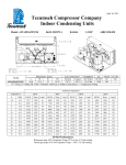
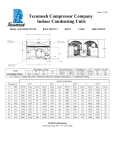
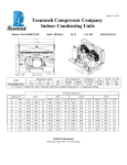
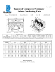
August 20, 2013 Revision: Release Tecumseh Compressor Company Indoor Condensing Units Model: VSA9514ZNAXM BoM: 2B3274-1 R-404A 1.5 HP AIRCOOLED Dimensions, inches Line Connection* Pumpdown Air L W H CH Suction Liquid 90 F 90% SCFM 33.8 25.0 19.5 17.7 5/8” S 3/8” S 16.5 lbs 1525 VSA9514ZNAXM * F = Flare, S = Solder, RF or RS = Rotolock with Flare or Solder Connections, C = Compression Fitting Model Oil Ch Oz. 24 Gr. Wt. Lbs. 290 Ambient Temperatures Evaporator T 80F 90F 100F 110F °F PSIG BTUH Watts Cond T BTUH Watts Cond T BTUH Watts Cond T BTUH Watts Cond T 0 33.5 10000 1750 92 9400 1890 102 8700 2040 111 7900 2200 120 5 36.5 11300 1780 94 10500 1920 103 9700 2080 112 8900 2240 121 10 42.4 12600 1810 95 11700 1960 104 10800 2120 113 9900 2280 122 15 48.2 14000 1840 97 13000 1990 105 12000 2150 114 11000 2330 123 20 54.5 15500 1870 98 14400 2030 107 13300 2190 115 12200 2370 124 25 61.2 17100 1900 100 15900 2060 108 14700 2230 117 13500 2410 125 30 68.4 18800 1930 101 17500 2090 110 16200 2270 118 14800 2450 126 35 76.1 20500 1960 103 19200 2130 112 17800 2310 120 16300 2490 128 40 84.4 22400 2000 105 20900 2170 113 19400 2350 121 17900 2540 129 45 94.3 24400 2040 107 22800 2220 115 21200 2400 123 19500 2590 131 60 Hz Performance Return gas temp. 40F Evaporator Temp. 20F or less, 5F sub-cooling Return gas temp. 65F for Evaporator Temp. > 20F, 5F sub-cooling August 20, 2013 Revision: Release Specifications/ Parts: Model Unit Bill of Material Nominal Volts-Hz-Ph Refrigeration Range Design Pressure Low Design Pressure High Voltage Range Min. Circuit Ampacity Max. Fuse Size (amps) Compressor Model Comp. Bill of Material Compressor RLA/LRA Overload Relay Run Capacitor Run Capacitor Rating Start Capacitor Start Capacitor Rating Contactor Unit Drawing Wiring Diagram VSA9514ZNAXM 2B3274-1 208-230-60-1 0° to 45° 181 450 187 to 254 16.3 25 VSA9512ZNA VS116ET-003-A4 11.9 / 65.9 INTERNAL 820ARR3J50 85PR370F17 35 MFD 370V (M) VDE 85PS330D76 88-108 MFD 330V VDE 91017 DGU1950-04 14949125 Fan Motor Fan Motor RLA Fan Blade Fan Guard Fan Shroud High Pressure Switch Low Pressure Control Dual Pressure Control Condenser Headmaster Valve * Check Valve * Receiver Tank Liquid Valve Liquid Filter * Sight Glass * Suction Valve Rotolock Valve Gasket Discharge Valve * Suction Filter * Accumulator Crankcase Heater * Defrost Timer * * = Outdoor Units Only Options for Outdoor Units Receiver Heater Solenoid Valve Electrical Diagram 810F050C20 (2) 0.70 51568-1 (2) 70831 (2) 70648-2 84095-2 84026-2 N/A 50858-1 N/A N/A 51081-1 31581-1 N/A N/A 31531-1 30233 31527-2 N/A TK00042000 N/A N/A N/A N/A