1
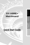
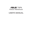
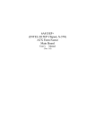
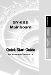
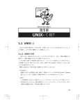
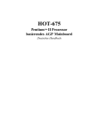
Quick Start Guide
Onboard Sound The SOYO CD
Driver Installation
Quick BIOS
Setup
Hardware
Installation
SY-6VZA
Motherboard
Introduction
SOYO ™
SY-6VZA Motherboard
Socket 370 for Intel CeleronTM processors
VIA Apollo Pro AGP/PCI Motherboard
66&100MHz Front Side Bus supported
ATX Form Factor
Copyright © 1998 by Soyo Computer Inc.
Trademarks:
Soyo is a registered trademark of Soyo Computer Inc. All trademarks are the property of their
owners.
Product Rights:
Product and corporate names mentioned in this publication are used for identification purposes
only and may be registered trademarks or copyrights of their respective companies.
Copyright Notice:
All rights reserved. This manual is copyrighted by Soyo Computer Inc. You may not reproduce,
transmit, transcribe, store in a retrieval system, or translate into any language, in any form or by
any means, electronic, mechanical, magnetic, optical, chemical, manual or otherwise, any part of
this publication without express written permission of Soyo Computer Inc.
Disclaimer:
Soyo Computer Inc. makes no representations or warranties regarding the contents of this
manual. We reserve the right to revise the manual or make changes in the specifications of the
product described within it at any time without notice and without obligation to notify any
person of such revision or change. The information contained in this manual is provided for
general use by our customers. Our customers should be aware that the personal computer field is
the subject of many patents. Our customers should ensure that their use of our products does not
infringe upon any patents. It is the policy of Soyo Computer Inc. to respect the valid patent rights
of third parties and not to infringe upon or assist others to infringe upon such rights.
Restricted Rights Legend:
Use, duplication, or disclosure by the Government is subject to restrictions set forth in
subparagraph (c)(1)(ii) of the Rights in Technical Data and Computer Software clause at
252.277-7013.
About This Guide:
This Quick Start Guide is for assisting system manufacturers and end users in setting up and
installing the Motherboard. Information in this guide has been carefully checked for reliability;
however, no guarantee is given as to the correctness of the contents. The information in this
document is subject to change without notice.
If you need any further information, please visit our Web Site on the Internet. The address is
"http://www.soyo.com.tw".
6VZA Serial - Version 1.0 - Edition: December 1998
* These specifications are subject to change without notice
2
1
Introduction
Congratulations on your purchase of the SY-6VZA Motherboard. This Quick Start Guide
describes the steps for installing and setting up your new Motherboard.
This guide is designed for all users to provide the basic steps of Motherboard setting and
operation. For further information, please refer to SY-6VZA Motherboard User's Guide and
Technical Reference online manual included on the CD-ROM packed with your
Motherboard.
Unpacking
* If your board comes with a driver disc and a paper manual, the Quick Start Guide and the CD-ROM are not included in the package.
When unpacking the Motherboard, check for the following items:
u The SY-6VZA VIA AGP/PCI Motherboard
u This Quick Start Guide
u The Installation CD-ROM
u One IDE Device Flat Cable
u One Floppy Disk Drive Flat Cable
3
Introduction
SY-6VZA Quick Start Guide
SY-6VZA Quick Start Guide
SY-6VZA Motherboard Layout
Hardware
Monitoring
Introduction
PS/2 KB PS/2 Mouse
Connector Connector
ATX Power
CPUFAN
Winbond
W83782
3
1
USB 1
1
USB 2
JP 2
JP1
Socket 370
PRT
COM 1
1
COM 2
FDC
JOYSTICK
IR1
LINE-OUT
5
LINE-IN
1
3
1
MIC JACK
3
JP44
WOL
AGP Slot
1 Header
J4
4
DIMM 3
I/O Chipset
DIMM 2
JP45
DIMM 1
1
Winbond
83977EF
-AW
CODEC
CT1297
1
IDE 2 IDE 1
J5
3V
Lithium
Battery
4
CDIN
1
PCI Slot #1
1
3
ES1373
AUDIO PCI
1
PCI Slot #2
_
JP8
3
1
JP7
Flash BIOS
Speaker
PCI Slot #3
+
Keylock
JP5
CMOS Clear
Jumper
_
HDD LED
+
_ Turbo
+ LED
PWRBT
_
PCI Slot #4
Power
LED
CHAFAN
+
Reset
1
ISA Slot #1
Key Features
Ø
Ø
Ø
Ø
Ø
Ø
Ø
Supports Intel CeleronTM processors (300A433MHz)
3D PnP Audio onboard
Auto-detect CPU voltage
PC98, ACPI, Ultra DMA/33
SOYO COMBO Setup
Supports Wake-On-LAN (WOL)
Supports onboard hardware monitoring and
includes Hardware Doctor ™ utility
Ø
Ø
Ø
Ø
Ø
Ø
Ø
Ø
4
Fan speed control
1 x 32-bit AGP slot
4x 32-bit bus mastering PCI slots
2 x USB ports onboard
1 x IrDA port
Supports multiple-boot function
Power failure resume
Supports Hardware Suspend (APM mode only)
SY-6VZA Quick Start Guide
2
Installation
l
Before handling the Motherboard, ground yourself by grasping an unpainted portion
of the system's metal chassis.
l
Remove the Motherboard from its anti-static packaging. Hold it by the edges and
avoid touching its components.
l
Check the Motherboard for damage. If any chip appears loose, press carefully to seat
it firmly in its socket.
Follow the directions in this section designed to guide you through a quick and correct
installation of your new SY-6VZA Motherboard. For detailed information, please refer to SY6VZA Motherboard User's guide and Technical Reference online manual included on the
CD-ROM packed with your Motherboard.
Gather and prepare all the necessary hardware equipment to complete the installation
successfully:
u CeleronTM processor with built-in CPU cooling fan (boxed type)
u SDRAM module
u Computer case and chassis with adequate power supply unit
u
u
u
u
u
u
u
u
Monitor
PS/2 Keyboard
Pointing Device (PS/2 Mouse)
VGA Card
Speaker(s) (optional)
Disk Drives: HDD, CD-ROM, Floppy drive …
External Peripherals: Printer, Plotter, and Modem (optional)
Internal Peripherals: Modem and LAN cards (optional)
Notice 1: This Motherboard features three built-in audio-stereo ports. Therefore you do not
need to install a sound card.
Notice 2: If you want to use an external speaker connected to "Line-out" port, please make
sure to use an "amplified speaker" that can generate proper output sound volume.
5
Hardware
Installation
To avoid damage to your Motherboard, follow these simple rules while handling
this equipment:
SY-6VZA Quick Start Guide
Install the Motherboard
Follow the steps below in order to perform the installation of your new SY-6VZA
Motherboard.
Step 1. Install the CPU
Mark your CPU Frequency: Record the working frequency of your CPU
that should be clearly marked on the CPU cover.
Hardware
Installation
300MHz (66 x 4.5)
400MHz (66 x 6.0)
333MHz (66 x 5.0)
433MHz (66 x 6.5)
366MHz (66 x 5.5)
This Motherboard is designed to be able to support processors with 100MHz FSB. However,
Socket 370 processors with 100MHz FSB are not available yet at this moment for testing.
CPU Mount Procedure: To mount the Celeron TM processor that you have
purchased separately, follow these instructions.
1
2
3
4
1.
Lift the socket handle up to a vertical position.
2.
Align the blunt edge of the CPU with the matching pinhole distinctive edge on the
socket.
3.
Seat the processor in the socket completely and without forcing.
4.
Then close the socket handle to secure the CPU in place.
Remember to connect the CPU Cooling Fan to the appropriate power
connector on the Motherboard. The fan is a key component that will ensure
system stability. The fan prevents overheating, therefore prolonging the life of
your CPU.
6
SY-6VZA Quick Start Guide
Make Connections to the Motherboard
This section tells how to connect internal peripherals and power supply to the Motherboard.
Step 2.
Internal peripherals include IDE devices (HDD, CD-ROM), Floppy Disk Drive, Chassis Fan,
Front Panel Devices (Turbo LED, Internal Speaker, Reset Button, IDE LED, and KeyLock
Switch.), Wake-On-LAN card, VGA card, Sound Card, and other devices.
Connectors and Plug-ins
Pin1
VCC
IrDA (Infrared Device Header): IR1
Pin2
Pin3
Pin4
None
IRRX
GND
Wake-On-LAN Header: JP44
Pin1
Pin2
Pin3
5VSB
GND
MP-Wakeup
Pin5
IRTX
CPU Cooling Fan: CPUFAN
Pin2
Pin3
Pin1
12V
SENSOR
GND
CD Line-in:J4,J5
Connect the CD Line-in cord from the CR-ROM device to J4
the matching connector J4 or J5
J5
Pin1
GND
Power LED Key Lock
Chassis Fan: CHAFAN
Pin2
Pin3
12V
SENSOR
Pin1
Pin2
Pin3
Pin4
L
G
G
R
Power LED
Speaker
L
G
R
G
Keylock
Pin1
Pin2
Pin3
GND
GND Control Pin
Speaker
1
1
1
1
Pin1
Pin2
Pin3
Pin4
5V
NC
NC
Speaker out
Reset PWRBT Turbo LED HDD LED
HDD LED
Turbo LED
PWRBT
RESET
Pin1
Pin2
Pin1
Pin2
Pin1
Pin2
Pin1
Pin2
LED
LED
Power
Power
LED Anode
GND
GND
GND
Cathode
Cathode
On/Off
Good
1
1
1
Pin1
5V
Pin2
NC
ATX Power On/Off: PWRBT
Connect your power switch to this header (momentary switch type).
To turn off the system, please press this switch and hold down for longer than 4 seconds.
ATX Power Supply: ATX PW
Attach the ATX Power cable to this connector. If you use ATX power supply.
When using the Power-On by PS/2 Keyboard function, please make sure the ATX power supply can
take at least 720mA load on the 5V Standby lead (5VSB) to meet the standard ATX specifications.
7
Hardware
Installation
For more details on how to connect internal and external peripherals to your new SY-6VZA
Motherboard, please refer to SY-6VZA Motherboard User's Guide and Technical Reference
online manual on CD-ROM.
SY-6VZA Quick Start Guide
Configure Memory
Your board comes with three DIMM sockets, providing support for up to 512MB of main
memory using DIMM modules from 8MB to 256MB.
Step 3.
Hardware
Installation
Memory Configuration Table
Number of
Memory Modules
DIMM 1
DIMM 2
1
Double-sided/Single-sided
Double-sided
2
Double-sided/Single-sided
3
Double-sided/Single-sided
RAM Type
Memory Module Size (MB)
DIMM 3
Double-sided
Single-sided
Single-sided
SDRAM
8/16/32/64/128/256 Mbytes
Note: Because DIMM banks 2 and 3 are shared, double-sided DIMMs can be
used in only one of the banks. With single-sided DIMM both bank 2 and 3 can
be used.
Step 4.
Set JP45 for power up FSB clock and AGP bus clock.
JP45 is used to adjust AGP bus clock frequency depending on the value of the front side bus
(FSB) clock, also the setting of the JP45 determines the power up FSB clock which will
remain effective until the BIOS set the FSB clock to the CMOS setting.
3
JP45 Setting
3
2
2
1
1
Power up FSB Clock
66MHz
100MHz
AGP Clock
AGP Clock = FSB Clock ÷ 1
AGP Clock = FSB Clock ÷ 1.5
Note: The specification of maximum AGP bus Clock frequency is 66.6MHz.
Set JP45 to pin 1-2 short when you use a FSB 100MHz CPU.
Set JP45 to pin 2-3 short when you use a FSB 66MHz CPU such as 300AMHz,
333MHz, 366MHz, etc.
∗ Set JP45 to pin 2-3 short when you use a FSB 66MHz but want to over clock the FSB
clock to 100MHz VIA the BIOS setting.
∗
∗
Set the CPU Frequency
This Motherboard does not use any jumpers to set the CPU frequency; CPU setting are
changed through the BIOS [SOYO COMBO SETUP]. Refer to Chapter 3 “Quick BIOS
Setup”for details on how to set the CeleronTM processor frequency.
Step 5.
8
SY-6VZA Quick Start Guide
Step 6.
Enable/Disable Power-On by Keyboard (JP1)
You can choose to enable the Power-On by Keyboard function by shorting pin 2-3 on jumper
JP1; otherwise, short pin 1-2 to disable this function.
JP1 Setting
Disable
Enable
Short pin 1-2 to the disable
Power-On by Keyboard
function.
3
Short pin 2-3 to enable the
Power-On by Keyboard
function
2
1
3
2
1
Important: When using the Power-On by Keyboard function, please make sure the
ATX power supply can take at least 720mAmp load on the 5V Standby lead (5VSB) to
meet the standard ATX specification.
Step 7.
Power Button Enable (JP8)
Your system can be power on by either pressing a power button or typing in a password,
which can be set in the BIOS SOYO COMBO Setup. To avoid being unable to power up the
system due to of forgetting the password, you can place a jumper cap to short JP8. This will
always enable the Power Button.
Power Button
Enable
JP8 Setting
Step 8.
Power Button always
enabled
Short pin to always
enable the Power
Button.
Power Button according to
BIOS setting
Open pin for a Power
Button function
according to the BIOS
setting.
External Suspend Button (JP2)
Some cases come with a suspend button, insert the plug into JP2. In addition to through this
button, the system can also enter the suspend mode through your OS.
Note: Suspend mode only functions if your Power Management mode is APM. Make sure that the BIOS
setting for Power Management is APM. Windows 98 can be installed with ACPI Power Management
(default is APM), in this case suspend mode will not function either.
9
Hardware
Installation
Power-On by
Keyboard
SY-6VZA Quick Start Guide
Step 9.
Enable/Disable Onboard Sound (JP7)
Hardware
Installation
The onboard audio features of your Motherboard are controlled by jumper JP7.You can
choose to enable or disable the available sound function by setting JP7 accordingly.
l
Short pin 1-2 on jumper JP7 to enable the onboard sound function. Then, you can plug
your external audio devices such as amplified-speakers, CD-player, and microphone
to the Motherboard Line-out, Line-in and Mic ports right after the Motherboard is
installed. (You do not need to install any sound card.)
l
To disable the onboard sound options short pin 2-3 on jumper JP7.
Onboard Sound
JP7 Setting
Enable
Short pin 1-2 to
enable the onboard
sound function.
Disable
3
2
1
Short pin 2-3 to
disable the onboard
sound function.
3
2
1
Step 10. Clear CMOS Data (JP5)
Clear the CMOS memory by momentarily shorting pin 2-3 on jumper JP5 for at least 5
seconds, and then by shorting pin 1-2 to retain new settings. This jumper can be easily
identified by its white colored cap.
CMOS Clearing
JP5 Setting
Clear CMOS Data
Short pin 2-3 for
at least 5 seconds
to clear the CMOS.
3
2
1
Retain CMOS Data
Short pin 1-2
to retain the
new settings.
3
2
1
Note: You must unplug the ATX power cable from the ATX power connector when
performing the CMOS Clear operation.
10
SY-6VZA Quick Start Guide
Note on Over-clocking Capability
1.
Turn off system power. (If you use an ATX power supply, and depending on your
system, you may have to press the power button for more than 4 seconds to shut
down the system.)
2.
Set JP45 to pin 2-3 if you use a FSB 66MHz CPU
3.
Press and hold down the <Insert> key while turning on the system power. Keep
holding down the <Insert> key until you see the message of the CPU type and your
CPU frequency (66MHz x CPU Multiplier) appear on screen.
4.
Press the <Del> key during the system diagnostic checks to enter the Award BIOS
Setup program.
5.
From the BIOS main menu, select [SOYO COMBO SETUP] and move the cursor to
the [CPU Frequency] field to set the proper working frequency.
6.
Select [Save & Exit SETUP] and press <Enter> to save the configuration to the
CMOS memory, and continue the boot sequence.
Note: SOYO does not guarantee system stability if the user over clocks the system.
Any malfunctions due to over-clocking are not covered by the warranty.
11
Hardware
Installation
The SY-6VZA Motherboard provides over-clocking capability. Due to the over-clocking
setting your system may fail to boot up or hang during run time. If this occurs, please perform
the following steps to recover your system from the abnormal situation:
SY-6VZA Quick Start Guide
3
Quick BIOS Setup
This Motherboard does not use any hardware jumpers to set the CPU frequency. Instead,
CPU settings are software configurable with the BIOS [SOYO COMBO SETUP]. The
[SOYO COMBO SETUP] menu combines the main parameters that you need to configure,
all in one menu, for a quick setup in BIOS.
After the hardware installation is complete, turn the power switch on, then press the <DEL> key
during the system diagnostic checks to enter the Award BIOS Setup program. The CMOS
SETUP UTILITY will display on screen. Then, follow these steps to configure the CPU settings.
Step 1.
Select [STANDARD CMOS SETUP]
Set [Date/Time] and [Floppy drive type], then set [Hard Disk Type] to “Auto”.
Quick BIOS
Setup
Step 2.
Select [LOAD SETUP DEFAULT]
Select the “LOAD SETUP DEFAULT”menu and type “Y”at the prompt to load the BIOS
optimal setup.
Step 3.
Select [SOYO COMBO SETUP]
Move the cursor to the [CPU Frequency] field to set the CPU frequency.
Available [CPU Frequency] settings on your SY-6VZA Motherboard are detailed in the
following table. If you set this field to [Manual], you are then required to fill in the next two
consecutive fields: (1) the CPU Host/PCI Clock, and (2) the CPU Ratio.
CPU Frequency
300MHz (66 x 4.5)
Select the working frequency of your Celeron TM
processor among these preset values.
333MHz (66 x 5.0)
366MHz (66 x 5.5)
400MHz (66 x 6.0)
Note:
Mark the checkbox that corresponds to
the working frequency of your Celeron TM processor
in case the CMOS configuration should be lost.
433MHz (66 x 6.5)
Note: if you use Bus Frequencies of 75 MHz, make sure that your PCI cards can cope with
the higher PCI clock.
Step 4.
Select [SAVE & EXIT SETUP]
Press <Enter> to save the new configuration to the CMOS memory, and continue the boot
sequence.
12
SY-6VZA Quick Start Guide
4
The SOYO CD
Your SY-6VZA Motherboard comes with a CD-ROM labeled "SOYO CD." The SOYO CD
contains the user's manual file for your new Motherboard, the drivers software available for
installation, and a database in HTML format with information on SOYO Motherboards and
other products.
Step 1.
Insert the SOYO CD into the CD-ROM drive
(SOYO CD Start Up Program Menu)
The SOYO CD Start Up Program automatically detects which SOYO Motherboard you own
and displays the corresponding model name.
Step 2.
Read SOYO [6VZA] Manual
Click the Read Manual button to open the user's manual file of your Motherboard.
13
The SOYO CD
The SOYO CD will auto-run, and the SOYO CD Start Up Menu will display as shown below.
SY-6VZA Quick Start Guide
Please note that if the Start Up program was unable to determine which SOYO Motherboard
you own, the manual selection menu will pop up, as shown below. Then select the user's
manual file that corresponds to your Motherboard model name and click OK.
SOYO CD Manuals
Please select your manual In the box below
and click OK.
6VZA
OK
Back
(Manual Selection Menu)
The SOYO CD
The user's manual files included on the SOYO CD can be read in PDF (Postscript
Document) format. In order to read a PDF file, the appropriate Acrobat Reader software
must be installed in your system.
Note: The Start Up program automatically detects if the Acrobat Reader utility is already
present in your system, and otherwise prompts you on whether or not you want to install it.
You must install the Acrobat Reader utility to be able to read the user's manual file. Follow
the instructions on your screen during installation, then once the installation is completed,
restart your system and re-run the SOYO CD.
Step 3.
Install Drivers and Utilities
The following describes the best way of installing Windows 95 or Windows 98 on your SY6VZA Motherboard:
Ø The following BIOS default settings should not be changed:
1. The ‘OnChip USB Controller’item under ‘Chipset features Setup’is set to enabled.
2. The ‘USB Assigned IRQ’item under ‘PnP/PCI Configuration is set to enabled.
You MUST have these two items enabled for Windows 95/98 to run properly on your
system.
Ø
Install Windows 95/98
Ø
After installation of windows, you will need to install the VIA drivers. Follow the
instruction below.
14
SY-6VZA Quick Start Guide
Click the Enter SOYO CD button to display the list of drivers that can be installed on your
Motherboard. The start-up program displays the drivers available for the SY-6VZA and the
Windows version you use. For Windows 95 four drivers will be listed (see ‘Driver Installation
Menu’below), for Windows 98 three drivers will be listed (the ACPI drivers will be left out).
Driver Installation
Please select the driver you want to install and click OK, You will have to
restart your system after installation. Only the drivers that are relevant
to your board are displayed initially.
VIA IRQ remapping utility
VIA ACPI Driver
SOYO SpeedPro BusMaster Driver
VIA Bus Master Driver
VIA VxD Driver
SOYO CD Xpress utility
System Monitor Utility
Creative Enxoniq Sound drivers
Display all drivers
on the SOYO CD
OK
(Driver Installation Menu)
A short description of all available drivers follows:
Ø
VIA IRQ remapping utility
This utility will remap the IRQ’s in the Apollo Pro chipset. For windows 95 and 98.
Ø
VIA ACPI Driver
This utility will help windows recognize your PCI bridge.
Ø
SOYO SpeedPro Busmaster Driver for Win 95/98
Without the busmaster drivers the CPU will need to be involved every time data is read from
or written to the Harddisk. The busmaster drivers make use of DMA (Direct Memory Access)
to relieve the CPU of this burden, thus speeding up the system.
The SOYO SpeedPro driver makes use of an advanced caching algorithm, which gives it an
advantage over other busmaster drivers.
Note: If you install the SOYO SpeedPro Busmaster driver for Windows 95/98, you can
NOT install the VIA Bus Master drivers.
15
The SOYO CD
Cancel
SY-6VZA Quick Start Guide
Ø
VIA Bus Master Driver
This is the VIA busmaster driver for Windows 95/98. Only install ONE type of busmaster
driver, and make sure to uninstall your previous busmaster driver first..
Ø
VIA VxD Driver
This is the VXD driver for the AGP port in your Apollo Pro chipset.
Ø
SOYO CD Xpress Utility
This utility will enhance your CD-ROM Drive data-thoughput by using space on the Harddisk
as cache. This way application programs can access data faster. This utility is suitable for
Windows 95/98.
Ø
System Monitor Utility
Your motherbaord comes with a hardware monitoring IC. By installing this utility Temperature,
Fan speed and Voltages can be monitored. It is also possible to set alarms when current
system values exceed or fall below pre-set values.
Ø
Creative Ensoniq Sound Drivers
The SOYO CD
These drivers have to be installed if the user wants to make use of the on-board Creative
Soundchip.
Select which driver you want to install and click OK, or click Cancel to return to the main
menu. When the installation program of a driver starts running the SOYO-CD will exit. After
finishing the installation, restart the SOYO-CD and install the next driver. We recommend
you to install all drivers, and to do so in the right sequence (top to bottom).
Note: Once you have selected a driver, the system will automatically exit the SOYO CD to
begin the driver installation program. When the installation is complete, most drivers require
to restart your system before they can become active.
Install the drivers in sequence, starting with the VIA IRQ remapping utility.
After installing all drivers above, if you use Windows 95, first install the
USB supplement before installing the AGP driver that came with your
AGP card.
The USB supplement is available on the Windows OSR 2 or above CD in the
following directory:\OSR2\usbsupp.exe
It also can be downloaded from www.microsoft.com
If you want to see all the drivers available on the SOYO –CD, click the Display all drivers
on the SOYO CD button. Do NOT install drivers that are not suitable for you board,
otherwise your system may crash.
16
SY-6VZA Quick Start Guide
Step 4.
Enter the SOYO CD
Click the Enter SOYO CD button to enter the SOYO HTML database. The Start Up program
will activate the default HTML browser installed on your system (for example, Internet
Explorer or Netscape) to visualize the contents of the SOYO CD.
(SOYO CD HTML Database in English*)
(* The list of menu options may vary between languages)
Note: If no HTML browser is installed on your system, the Start Up program will prompt you
on whether or not you would like to install the Internet Explorer* browser. Click YES to install
the HTML browser. After the installation is complete, please restart your system. Then re-run
the SOYO CD and you will be able to browse the SOYO HTML database.
(* Internet Explorer is a Microsoft Trademark)
17
The SOYO CD
The SOYO CD contains useful information about your Motherboard and other SOYO
products available in as many as eleven different languages. For your convenience, this
information is available in HTML format, similar to the format widely used on the Internet.
SY-6VZA Quick Start Guide
5
Onboard Sound Driver Installation
Installing AudioPCI in Windows 95/98
To install the audio drivers in Windows 95/98, insert the SOYO CD into your CD-ROM drive. It will auto-run
(If not, run Cdstart.exe in the root of the CD). Now press the install the 6VZA drivers button, select
‘Creative Ensoniq Sound drivers’and press ‘OK’. The driver installation program will be run, follow the
instructions on the screen.
Installing AudioPCI in Windows NT4.0
This section shows you how to properly install the audio drivers under Windows NT 4.0. It contains the
following sections:
Ø
Installing Software in Windows NT 4.0.
Ø
Testing the Installation in Windows NT 4.0
Ø
Uninstalling AudioPCI in Windows NT 4.0
Ø
Reinstalling the Audio Drivers From the Installation Disc
Installing Software in Windows NT 4.0
To install the software:
The software installation in NT 4.0 includes the installation of audio drivers.
1.
2.
Insert the installation CD into your CD-ROM drive. The AutoPlay screen appears,
Follow the instructions on the screen to complete the installation.
Onboard Sound
Driver Installation
Testing the Installation in Windows NT 4.0
You may run a simple application to test the card’s MIDI and wave sound playback. This ensure that the
cared is properly installed and that there are no conflicts in the IRQ. DMA, or I/O settings.
To test the installation:
1.
In the Start menu, point to Programs, point to Programs. point to Accessories, point to Multimedia.
and then click [Media Player].
2.
On the File menu, click [Option].
3.
Browse to any folder that contains a file with the extension way. Select the file and click the [Open]
button. Click the [Play] button to play the file.
18
SY-6VZA Quick Start Guide
Uninstalling AudioPCI in Windows NT 4.0
To uninstall the software:
1.
2.
3.
Click the [Start] button, point to Settings and click [Control Panel]. Double-click the Multimedia icon.
From the Audio Devices tabbed page, Select any existing audio devices and then click Remove.
Click [Yes] when prompted to remove the driver.
Close the Multimedia Properties windows and restart your computer.
Reinstalling the Audio Drivers From the Installation Disc
You may want to reinstall the audio drivers if you think they are corrupted. To do so:
1.
2.
Insert the installation CD into you CD-ROM drive.
Run the UPDPCINT.EXE program from the D:\ drivers\ensoniq\Language\NT4DRV folder, where
D: represents your CD-ROM drive and Language represents the language of the software that you
want to install.
Onboard Sound
Driver Installation
A brief message appears. Then the pointer returns to its normal shape, indicating that the update is
complete.
19
Edition: December 1998
Version 1.0
6VZA SERIAL
International Headquarters
Soyo Computer Inc., (Taiwan)
Tel: 886-2-2290-3300
Fax: 886-2-2298-3322
Web Site: http://www.soyo.com.tw
E-mail: [email protected]
USA Branch Office
SOYO TEK Inc., (USA)
Tel: 1-510-226-7696
Fax: 1-510-226-9218
Web Site: http://www.soyousa.com
E-mail: [email protected]
SOYO Europe
Soyo Europe B.V., (Holland)
Tel: 31-79-3637500
Fax: 31-79-3637575
Web Site: http://www.soyo-europe.com
http://www.soyo.nl
E-mail: [email protected]
Germany Branch Office
SAAT TECHNOLOGY GmbH
Tel: 49-(0)441-209100
Fax: 49-(0)441-203422
Web Sites:http://www.saat.de
http://www.soyo-saat.de
http://www.soyo-saat.com
Email: [email protected]
UK Branch Office
Soyo (U.K.) Ltd.
Tel: 44-(0)181-569 4111
Fax: 44-(0)181-569 4134
Web Site: http://www.soyo.nl
E-mail: [email protected]
Japan Branch Office
Soyo Computer (Japan)
Tel: 81-3-33682188
Fax: 81-3-33682199
Web Site: http://www.soyo.co.jp
E-mail: [email protected]
Hong Kong Branch Office
Soyo Hong Kong Ltd. (H.K.)
Tel: 852-2710-9810
Fax: 852-2710-9078
Web Site: http://www.soyo.com.hk
E-mail: [email protected]