1
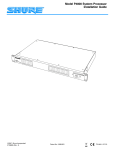
Model DP11EQ User’s Guide
DP11EQ
Dynamics Processor, Equalizer, and Delay
with Windows Software
E2006, Shure Incorporated
27A8630 (Rev. 2)
TABLE OF CONTENTS
INTRODUCTION . . . . . . . . . . . . . . . . . . . . . . . . . . . . . . . . . . . . . . . . . . . . . . . . . . . . . . . . . . . . . . . . . . . . . . . . . English – 2
Hardware Features . . . . . . . . . . . . . . . . . . . . . . . . . . . . . . . . . . . . . . . . . . . . . . . . . . . . . . . . . . . . . . . . . . . . . . English – 2
Software Features . . . . . . . . . . . . . . . . . . . . . . . . . . . . . . . . . . . . . . . . . . . . . . . . . . . . . . . . . . . . . . . . . . . . . . English – 2
DP11EQ HARDWARE . . . . . . . . . . . . . . . . . . . . . . . . . . . . . . . . . . . . . . . . . . . . . . . . . . . . . . . . . . . . . . . . . . . English – 3
Overview . . . . . . . . . . . . . . . . . . . . . . . . . . . . . . . . . . . . . . . . . . . . . . . . . . . . . . . . . . . . . . . . . . . . . . . . . . . . . . English – 3
Audio Connections . . . . . . . . . . . . . . . . . . . . . . . . . . . . . . . . . . . . . . . . . . . . . . . . . . . . . . . . . . . . . . . . . . . . . . English – 5
DP11EQ SOFTWARE . . . . . . . . . . . . . . . . . . . . . . . . . . . . . . . . . . . . . . . . . . . . . . . . . . . . . . . . . . . . . . . . . . . . English – 7
Introduction . . . . . . . . . . . . . . . . . . . . . . . . . . . . . . . . . . . . . . . . . . . . . . . . . . . . . . . . . . . . . . . . . . . . . . . . . . . . English – 7
Overview . . . . . . . . . . . . . . . . . . . . . . . . . . . . . . . . . . . . . . . . . . . . . . . . . . . . . . . . . . . . . . . . . . . . . . . . . . . . . . English – 9
MAIN CONTROLS . . . . . . . . . . . . . . . . . . . . . . . . . . . . . . . . . . . . . . . . . . . . . . . . . . . . . . . . . . . . . . . . . . . . . . English – 10
DYNAMICS PROCESSOR . . . . . . . . . . . . . . . . . . . . . . . . . . . . . . . . . . . . . . . . . . . . . . . . . . . . . . . . . . . . . . . English – 11
Overview . . . . . . . . . . . . . . . . . . . . . . . . . . . . . . . . . . . . . . . . . . . . . . . . . . . . . . . . . . . . . . . . . . . . . . . . . . . . . English – 11
Dynamics Parameters . . . . . . . . . . . . . . . . . . . . . . . . . . . . . . . . . . . . . . . . . . . . . . . . . . . . . . . . . . . . . . . . . English – 12
Dynamics Processes . . . . . . . . . . . . . . . . . . . . . . . . . . . . . . . . . . . . . . . . . . . . . . . . . . . . . . . . . . . . . . . . . . English – 13
Gate . . . . . . . . . . . . . . . . . . . . . . . . . . . . . . . . . . . . . . . . . . . . . . . . . . . . . . . . . . . . . . . . . . . . . . . . . . . . . . . . English – 13
Expander . . . . . . . . . . . . . . . . . . . . . . . . . . . . . . . . . . . . . . . . . . . . . . . . . . . . . . . . . . . . . . . . . . . . . . . . . . . . English – 13
AGC Leveler . . . . . . . . . . . . . . . . . . . . . . . . . . . . . . . . . . . . . . . . . . . . . . . . . . . . . . . . . . . . . . . . . . . . . . . . . English – 14
Compressor . . . . . . . . . . . . . . . . . . . . . . . . . . . . . . . . . . . . . . . . . . . . . . . . . . . . . . . . . . . . . . . . . . . . . . . . . . English – 15
Limiter . . . . . . . . . . . . . . . . . . . . . . . . . . . . . . . . . . . . . . . . . . . . . . . . . . . . . . . . . . . . . . . . . . . . . . . . . . . . . . . English – 15
No Overshoot Peak Limiter . . . . . . . . . . . . . . . . . . . . . . . . . . . . . . . . . . . . . . . . . . . . . . . . . . . . . . . . . . . . . English – 16
PARAMETRIC EQUALIZER . . . . . . . . . . . . . . . . . . . . . . . . . . . . . . . . . . . . . . . . . . . . . . . . . . . . . . . . . . . . . . English – 17
DELAY . . . . . . . . . . . . . . . . . . . . . . . . . . . . . . . . . . . . . . . . . . . . . . . . . . . . . . . . . . . . . . . . . . . . . . . . . . . . . . . . . English – 21
SHURE LINK NETWORKS . . . . . . . . . . . . . . . . . . . . . . . . . . . . . . . . . . . . . . . . . . . . . . . . . . . . . . . . . . . . . . . English – 23
MAINTENANCE . . . . . . . . . . . . . . . . . . . . . . . . . . . . . . . . . . . . . . . . . . . . . . . . . . . . . . . . . . . . . . . . . . . . . . . . English – 24
Scenes . . . . . . . . . . . . . . . . . . . . . . . . . . . . . . . . . . . . . . . . . . . . . . . . . . . . . . . . . . . . . . . . . . . . . . . . . . . . . . English – 24
Settings . . . . . . . . . . . . . . . . . . . . . . . . . . . . . . . . . . . . . . . . . . . . . . . . . . . . . . . . . . . . . . . . . . . . . . . . . . . . . English – 25
Customizing Graph Colors . . . . . . . . . . . . . . . . . . . . . . . . . . . . . . . . . . . . . . . . . . . . . . . . . . . . . . . . . . . . . English – 25
Printing DP11EQ Settings . . . . . . . . . . . . . . . . . . . . . . . . . . . . . . . . . . . . . . . . . . . . . . . . . . . . . . . . . . . . . . English – 26
Locking Out the Front Panel . . . . . . . . . . . . . . . . . . . . . . . . . . . . . . . . . . . . . . . . . . . . . . . . . . . . . . . . . . . . English – 26
Exiting the DP11EQ Application . . . . . . . . . . . . . . . . . . . . . . . . . . . . . . . . . . . . . . . . . . . . . . . . . . . . . . . . . English – 26
APPENDIX A. SPECIFICATIONS . . . . . . . . . . . . . . . . . . . . . . . . . . . . . . . . . . . . . . . . . . . . . . . . . . . . . . . . . English – 26
APPENDIX B. RACK MOUNTING THE DP11EQ . . . . . . . . . . . . . . . . . . . . . . . . . . . . . . . . . . . . . . . . . . . . English – 28
APPENDIX C. CONNECTORS AND CABLES . . . . . . . . . . . . . . . . . . . . . . . . . . . . . . . . . . . . . . . . . . . . . . English – 29
APPENDIX D. KEYBOARD CONTROLS . . . . . . . . . . . . . . . . . . . . . . . . . . . . . . . . . . . . . . . . . . . . . . . . . . . English – 33
*Trademark Notifications: Shure is a registered trademark of Shure Brothers, Inc. Windows is
a registered trademark of Microsoft Corporation. Crystal is a trademark of Crystal Semiconductor
Corporation. Motorola is a registered trademark of Motorola, Inc. IBM is a registered trademark of
the IBM Corporation.
English – 1
INTRODUCTION
DATA
The Shure Model DP11EQ is a single-channel, digital signal processor that combines a
comprehensive dynamics processor, two parametric equalizers, and a delay in a single, half-rack
enclosure. The DP11EQ can function as a gate, expander, Automatic Gain Control (AGC) leveler,
compressor, limiter, and no overshoot peak limiter. All of these features are accessed via the
supplied Windows* software. You can connect a computer to set up the unit in a sound system, then
remove the computer so no one can tamper with the settings when the unit is left unattended. The
DP11EQ is designed for installed sound reinforcement applications: theater, conference rooms,
meeting halls, houses of worship, etc.
Hardware Features
S
Crystal* 20-bit A/D and D/A converters
(Analog-to-Digital, Digital-to-Analog) for 104 dB
dynamic range.
S
A SIGNAL presence and a CLIP indicator
S
DYNAMIC GAIN meter.
S
48 kHz sampling rate for flat response to 20 kHz.
S
S
Half-rack space chassis allows rack mounting of
one or two units in a single rack space with no
sagging or bending.
Shure Link connectors for networking to other
Shure Link devices, such as the models
DFR11EQ and UA888.
S
Shure Link Interface allows multiple units to be
programmed with a single computer.
S
S
Independently driven, cross-coupled, balanced
1/ -inch and XLR outputs. Can be used with
4
balanced or unbalanced inputs.
Four (4) processing blocks: pre-dynamics
equalizer (EQ1), dynamics (DYN), post-dynamics
(EQ2), and Delay.
S
Electronically balanced input with combination
1/ -inch and XLR connector. Can be used with
4
balanced or unbalanced outputs.
The dynamics processor functions as a Gate,
Expander, AGC Leveler, Compressor, Limiter, and
No Overshoot Peak Limiter.
S
The parametric equalizer offers up to 10 filters
with adjustable frequency, up to 6 dB of boost or
–18 dB of cut per filter, 1/40 to 2 octave bandwidth.
S
Response Viewing. The dynamics and equalizer
windows each have a viewer which shows the
effect of the process on the signal.
S
Up to 1.3 seconds of Digital Delay with
temperature compensation option. Displayed in
time and distance.
S
Digitally-controlled signal polarity inverting for
equipment that inverts balanced signals.
S
Front panel lockout control to prevent tampering.
S
Storage of multiple scenes to floppy or hard disk.
S
Software Features
S
No internal batteries. Settings and DSP program
stored in internal EEPROM.
S
+4 dBu/–10 dBV DIP-switch-selectable input and
output levels.
S
80 MHz Motorola* DSP56009 processor engine
with full 24-bit internal processing.
S
RS-232 interface for external computer control
and firmware updates.
S
Internal linear power supply eliminates the need
for a cumbersome external power supply.
S
Solid state bypass eliminates unreliable
mechanical relays and switches.
English – 2
DP11EQ HARDWARE
Overview
Front Panel
DATA
Ê ËÌ
Ê
Ë
Ì
Í
BYPASS Button and LED. Press this button to
suspend all signal processing from the audio path.
When the LED illuminates, the dynamics
processor, delay, and the equalizers are
bypassed.
SIGNAL LED. Illuminates when input signal is
present. Intensity varies with input signal level.
CLIP LED. Illuminates when the input signal is
within 6 dB of clipping.
Í
Î
Ï
Î Ï
Dynamic Gain Meters. The 7 red LEDs on the left
indicate the reduction in dynamic range, while the
three yellow LEDs on the right indicate dynamic
boost.
DATA LED. This LED indicates that the computer
is communicating with the unit via the RS-232 port.
POWER LED.
powered on.
LED illuminates when unit is
Back Panel
ÑÑ
ÑÑ ÑÑ
ÑÑ
ÑÑ
Ê
Ê
Ë
Ì
Í
Ë
Ì
Í
Power Connector with Integral Fuse. Connects
to AC power. The fuse is located in the drawer
below the connector.
Î
9-Pin RS-232 Port. Connects the unit to a
computer. For use with DP11EQ software and for
DSP firmware upgrades.
Shure Link Interface. Allows linking of up to 16
Shure Link compatible devices which may be
accessed by a single computer.
Ï
DIP Switches. See DIP Switches.
English – 3
Î
Ï
Output Connector—1/4-Inch & XLR. Active,
cross-coupled, balanced outputs can be used with
balanced or unbalanced inputs. Can be switched
between +4 dBu/–10 dBV line-level operation by
1/ -Inch and XLR are driven
DIP switch.
4
independently and either can be balanced or
unbalanced without affecting the other.
Input Connector—Combined XLR and
1/ -Inch. Active balanced input can be used with
4
balanced or unbalanced outputs. Can be switched
between +4 dBu/–10 dBV line-level operation by
DIP switch.
DIP Switches
The DIP switches located on the rear panel are used for adapting the unit to the sound system
requirements. See the table below.
DIP
SWITCH
FUNCTION
1–4
Device ID
5–8
unused
POSITION
UP
DOWN
see below
see below
—
—
9
Output Sensitivity
+4 dBu
–10 dBV
10
Input Sensitivity
+4 dBu
–10 dBV
Shure Link Device ID
When multiple DP11EQ s are linked, each one must be assigned a unique Device ID, 0 through
15. DIP switches 1 through 4 on the rear panel are used to set the Device ID. To change the Device
ID, align the switches according to the illustrations below. The unit comes factory preset to Device ID
15.
DEVICE ID 0
SWITCH UP
1
2
3
DEVICE ID 1
4
DEVICE ID 4
1
SWITCH DOWN
2
3
2
3
4
2
3
3
4
1
2
3
4
1
2
3
4
1
2
3
2
3
4
1
2
3
4
1
2
3
4
English – 4
1
2
3
2
3
4
1
2
3
4
DEVICE ID 11
4
DEVICE ID 14
4
1
DEVICE ID 7
DEVICE ID 10
DEVICE ID 13
4
1
DEVICE ID 3
DEVICE ID 6
DEVICE ID 9
DEVICE ID 12
1
2
DEVICE ID 5
DEVICE ID 8
1
1
DEVICE ID 2
1
2
3
4
DEVICE ID 15
4
1
2
3
4
Audio Connections
The DP11EQ is a flexible unit which can be used in almost any part of a sound system. It can be
placed directly in an input channel’s insert and used as an equalizer solely for that microphone. Or, it
can be placed at a mixer subgroup insert, where it can act as a compressor, equalizer, and noise gate
for a group of microphones. Or, it can be placed between the mixer and the power amplifier to
equalize overall room sound and function as a limiter to protect the loudspeakers from damage due to
clipping.
The following diagrams show several typical connections:
S
S
S
Main Amplifier
Subgroup Insert
Input Insert
NOTE: See Appendix C. for descriptions of cable and connection information.
Main Amplifier
The DP11EQ is most commonly placed between the main output of a mixer and the input of a
power amplifier. At the main output, the unit will affect all input channels. This setup is ideal for using
the DP11EQ as a dynamics processor and as an equalizer.
LINE IN
ÑÑÑ
Ñ
ÑÑÑÑÑÑÑÑÑÑÑÑÑÑ
ÑÑÑ
ÑÑ
ÑÑÑÑÑÑÑÑÑÑÑÑÑ
Ñ
ÑÑÑÑÑÑÑÑÑÑÑÑ
Ñ
ÑÑ
Ñ
Ñ
Ñ
ÑÑÑÑÑÑ
Ñ
Ñ
Ñ
ÑÑ
Ñ
ÑÑ
Ñ
Ñ
ÑÑÑÑÑÑÑÑÑÑÑÑÑÑÑ
ÑÑ
ÑÑÑÑÑÑÑÑÑÑÑÑÑ
Ñ
ÑÑ
ÑÑ
Ñ
ÑÑ
Ñ
ÑÑ
Ñ
Ñ
ÑÑ
ÑÑÑÑÑÑÑÑ
ÑÑ
Ñ
ÑÑ
Ñ
Ñ
ÑÑ
Ñ
ÑÑ
Ñ
Ñ
Ñ
ÑÑ
Ñ
ÑÑÑÑÑÑÑÑÑÑÑÑÑÑÑ
ÑÑÑÑÑÑÑÑÑÑ
ÑÑ
ÑÑÑÑÑÑÑÑÑÑÑÑÑ
Ñ
ÑÑ
Ñ
Ñ
Ñ
ÑÑ
ÑÑ
Ñ
ÑÑ
Ñ
ÑÑ
Ñ
Ñ
ÑÑ
Ñ
ÑÑ
Ñ
ÑÑÑ
Ñ
Ñ
Ñ
ÑÑÑÑÑÑÑÑÑÑÑÑÑÑÑ
ÑÑ
ÑÑÑÑÑÑÑÑÑÑÑÑÑ
ÑÑ
ÑÑ
Ñ
Ñ
Ñ
Ñ
ÑÑÑÑÑ
ÑÑÑ
Ñ
DP11EQ
Ñ Ñ
LINE IN
POWER AMPLIFIER
LINE OUT
LINE OUT
LOUDSPEAKER
MIXER
Subgroup Insert
When using a multiple bus mixer, the DP11EQ can be connected to a single subgroup insert. The
unit will affect only the channels associated with that subgroup: the other channels will remain
unaffected. This is a common set up for dynamically controlling a specific group of signals, for
example, a group of vocal microphones.
SUB SEND
SUB RETURN
ÑÑ Ñ
Ñ
Ñ
ÑÑ
Ñ
ÑÑ
LINE
OUT
MAIN
Ñ ÑÑ
Ñ
LINE IN
ÑÑ
DP11EQ
LINE IN
POWER AMPLIFIER
LINE OUT
LOUDSPEAKER
MIXER
English – 5
Input Insert
The DP11EQ can be placed directly on a single microphone insert to process the signal for that
microphone only. This is a common location for an leveler.
CHANNEL 1 IN
CHANNEL 1
INSERT
ÑÑ Ñ
LINE
OUT
MAIN
Ñ ÑÑ
Ñ
LINE IN
ÑÑ
LINE OUT
LINE IN
POWER AMPLIFIER
DP11EQ
LOUDSPEAKER
MIXER
LINE OUT
WIRELESS RECEIVER
LAVALIER MICROPHONE
AND WIRELESS TRANSMITTER
English – 6
DP11EQ SOFTWARE
Introduction
This section describes the Windows-based computer interface software which allows you to
control the Shure DP11EQ . The software controls a dynamics processor which can operate as a
gate, expander, leveler, compressor, limiter, and no overshoot peak limiter. There are parametric
equalizers placed before and after the dynamics processor. In addition, there is a digital delay which
can add up to 1.3 seconds of delay from input to output.
Minimum Computer Requirements
The following are the minimum requirements to run the Shure DP11EQ software.
S
S
S
S
S
S
One 486DX 50 MHz IBM*-compatible computer (math coprocessor required)
2 MB hard drive space
4 MB RAM
Windows version 3.1x, or greater
1 available RS-232 serial (COM) port
One RS-232 cable to connect the COM port of the computer to the DB-9
connector of the DP11EQ
Connecting the DP11EQ to a Computer via the RS-232 (COM) Port
Before connecting the DP11EQ to the computer, determine whether the computer’s RS-232
(COM) port is 9-pin or 25-pin. Use the proper cable (purchased separately). For RS-232 cable
diagrams, see Appendix C. Cables and Connectors.
ÑÑ
Ñ
Ñ
ÑÑÑ
ÑÑ
ÑÑ
TO COMPUTER
RS-232 CONNECTOR
TO DP11EQ
RS-232 CABLE
(9-PIN MALE)
1. Connect the 9-pin plug (male) of the cable to the RS-232 port of the DP11EQ .
2. Connect the other end of the cable to the RS-232 port of the computer.
Software Installation
1. Insert the supplied 3.5-in floppy disk into the disk drive of your computer.
2. For computers running Windows 95 or Windows NT, click on the Start button , then
select Run...
For computers running Windows 3.1, click on the File heading of the main menu of the
Program Manager, then click on Run...
3. In the Run window, type “a:\setup”, where “a” is the drive containing the disk.
4. Shure Setup will suggest a destination on your hard disk for the DP11EQ files. Shure
Setup will check the computer hardware to ensure that a coprocessor is present. Setup
will also prompt you for your name and organizational information.
NOTE: Remember to register your software by filling out and mailing the
enclosed registration card, or online via the Shure World Wide Web site
(“http://www.shure.com”). This will ensure that you receive information about
software updates with additional features as they become available.
English – 7
The Shure Program Group
The Shure program group contains the main application icon, a Windows Help file, and a
Readme file with the most up-to-date information. To launch the application, double-click on the
DP11EQ icon. This group will also contain other Shure software stored on your hard drive.
Configuring the Computer Serial Port
1. Launch the DP11EQ software.
2. Click on Communications in the main menu bar.
3. Click on the COM port option of the drop-down menu.
4. In the Serial Port Options window, select an available COM port on the computer.
5. Click on the OK button.
NOTE: The COM port selection is saved in the DP11EQ.INI file, and will not
need to be selected again unless you need to change the hardware
configuration.
Accessing the Connected DP11EQs
To bring the networked DP11EQ’s online, click on the CONNECT button of the Main Control
Panel, or select the Connect option of the Communications drop-down menu of the main menu bar.
The program searches for each unit connected in the network, reading the Shure Link Device ID of
each.
English – 8
Overview
Main Control Panel. In the main control panel,
there is button for muting the sound. There is also
a button for bypassing overall processing, allowing
you to hear the unaffected sound. There is also a
Processor Select virtual signal path which allows
access to the control panels for the separate
processes. There is also a Dynamic Gain meter
corresponding to the LEDs on the front panel of
the DP11EQ. The Connect button accesses any
units connected to a computer.
Dynamics Processor Panel. In the Dynamics
Processor Panel, there is a Dynamics Select
virtual signal path to select the desired dynamics
process. The dynamics graph allows you to view
changes to the signal dynamics while you make
adjustments. To the right, there are several fields
which allow you to adjust parameters. Near the
top, there is a Dynamic Gain meter corresponding
to the one on the front panel of the DP11EQ.
There are also Snapshot buttons for storing and
viewing an original response curve while making
adjustments, a Clear button, a Threshold Offset
slider and an Output gain slider.
English – 9
Parametric Equalizer Panels. There are two
parametric equalizers in the unit. Each one has
high- and low- frequency filters which can be set
as shelf or cut, along with additional parametric
filters. There is a response curve viewer, an
Output gain slider, and IN/OUT meters. There are
also Snapshot buttons, a Clear button, and a
New button for setting new parametric filters.
Delay Panel. The Delay Panel allows you to set
the delay in milliseconds, meters, feet, or inches.
You can also set the air temperature in Fahrenheit
or Celsius to compensate for room temperature
when setting delay by distance. The delay panel
also includes a Clear button for removing any
unwanted settings.
MAIN CONTROLS
The top panel contains the main controls for the DP11EQ software.
CURRENT DEVICE ID
SCENE NAME
UNIT NAME
STATUS
Main Menu. The main menu contains options for
connecting, storing and recalling scenes, and
networking with other DP11EQs and DFR11EQs.
There is also a help file for online assistance.
MUTE Button and LED. This button mutes the
audio output of the DP11EQ. The LED is red when
muted.
BYPASS Button and LED. This button removes
all processing from the signal path. The LED is red
when the DP11EQ is bypassed.
PROCESSOR SELECT Buttons.
Processor Select Buttons, below.
DYNAMIC GAIN Meter. This meter displays the
net gain of the unit.
CONNECT Button and LED. This button brings
the DP11EQ plugged into the computer online,
along with any other devices networked via Shure
Link. When connected, the LED is green.
Processor Select Buttons
The Processor Select buttons form a virtual signal path representing the flow of the audio signal
through the DP11EQ. Each button accesses one of the signal processor panels. When you click on
one of these buttons, the window for controlling that processor block will appear, allowing you to
adjust these processes. The BYPASS buttons below each block allow you to bypass individual
processors in the signal path.
Each block is as follows:
EQ1 — This is the pre–DYN equalizer block.
DYN — This is the dynamics block.
EQ2 — This is the post–DYN equalizer block.
DELAY — This is the delay block.
English –10
See
DYNAMICS PROCESSOR
Dynamic range is the difference between the loudest and quietest levels of an audio signal.
Controlling dynamic range plays an important role in good audio quality. Using the DP11EQ
Dynamics Processor, you can control the dynamics of a sound system to improve audio quality. You
can use the gate or expander to mute or lower the sound when no one is talking, use the leveler to
raise the audio level if the source sound is too quiet, quieten sounds that are too loud with the
compressor, and protect your amplifier from sudden bursts with the limiter and no overshoot peak
limiter.
Overview
DYNAMICS SELECT Buttons. The individual
dynamics processes are ordered from left to right
indicating the signal flow. Click on these buttons
to access the different Dynamics processes. Click
on these buttons a second time to bypass each
process.
DYNAMIC GAIN Meter. This meter indicates the
total gain based on the current settings and input
level. Click on this meter to activate.
Dynamics Transfer Curve Graph. This displays
the effect of all dynamics processing on the input
signal.
Dynamic Input/Output Meter. Embedded in the
graph is a meter which displays the input levels
and the relative output levels, so you can see how
the DP11EQ is affecting the current program
material. The horizontal axis represents the input
level (A), while the vertical axis represents the
resulting output level (B). This meter functions
when the Dynamic Gain meter is active.
English –11
PARAMETER BOXES. These boxes can be used
for fine-tuning dynamics parameters.
THRESHOLD OFFSET Slider.
This slider
adjusts the threshold settings of all dynamics
processes simultaneously. This allows rapid
tuning of a scene to the particular signal levels of
an audio system. Click and drag this slider to
adjust the threshold offset.
OUTPUT Slider. This slider controls the output
gain of the dynamics processor. Click and drag
this slider to adjust the output level.
SNAPSHOT Buttons. Snapshots can be used
for viewing original response curves while making
adjustments.
DYNAMICS CLEAR Button. Click on this button
to clear the currently selected dynamics process,
or all processes.
Dynamics Parameters
The edit boxes are used to adjust the parameters of each dynamics process. This section gives
general definitions of the parameters. See Dynamics Processes for more specific information.
THRESHOLD.
The Threshold parameter
determines the input level at which dynamics
processing begins.
For the gate and the
expander, processing is activated by signal levels
below the threshold. The AGC, the compressor,
the limiter, and the peak limiter are triggered by
signal levels above the threshold. To adjust the
threshold, click and drag the “T” box at the top of
the graph, or click on the ↑ and ↓ buttons of the
THRESHOLD edit box.
ATTACK. The Attack parameter controls the
amount of time it takes for a gain change to take
full effect once a threshold has been crossed. To
adjust the attack, click on the ↑ and ↓ buttons of
the ATTACK box, or type the desired value in the
edit box.
English –12
RATIO. The Ratio determines how much the
processor will affect the sound. For example, if the
compressor is set to a ratio of 2:1, for every 2 dB
increase of the input signal above the threshold,
the increase of the output signal will be only 1 dB.
To adjust the ratio, click and drag the “R” box at the
right side of the graph, or click on the ↑ and ↓
buttons of the RATIO edit box.
DECAY. The Decay parameter controls the time
it takes for the gain to return to unity once the
selected process is complete. To adjust the decay,
click on the ↑ and ↓ buttons of the DECAY box, or
type the desired value in the edit box.
Auxiliary Box. This control functions differently
for each dynamics process. See the Dynamics
Processes section following for definitions.
Dynamics Processes
Gate
Definition: A gate mutes an input signal when it drops below a user defined threshold. Every
sound system has a certain amount of noise or hiss. Some of this noise is in the background (the
hissing of air conditioners), and some may be caused by electrical sources affecting the equipment
(electromagnetic hum caused by fluorescent lights). This noise and hiss is usually at such a low level
that it is drowned out when there is program material present. However, if the program material is
temporarily stopped, as when a talker pauses, the noise becomes noticeable and lowers overall
sound quality. In this situation, the gate mutes the signal path temporarily so that background noise
would not be heard. Then, when the talker starts again, the gate would open, allowing the sound
through the system.
Application: A gate is used to mute low-level noise and hiss whenever the program material
drops below the threshold.
For the Gate, the parameters and controls function as follows:
GATE Select Button. Click on this button to activate the gate. Click a second time to bypass.
THRESHOLD. The threshold determines the level below which the gate begins to operate.
Any audio levels below the gate threshold will be muted. To adjust the threshold, click and drag
the “T” box at the top of the graph, or click on the ↑ and ↓ buttons of the THRESHOLD field.
RATIO. The ratio determines the amount of gating. If the ratio settings are less than ∞:1, then
the block is functioning as an expander (see Expander).
ATTACK. The attack determines the amount of time before the gate returns to unity gain after
the input level rises above the threshold.
DECAY. The decay controls the amount of time before the signal is muted once the input level
decreases below the threshold.
GATE HOLD. The gate hold determines the amount of time the DP11EQ sustains the gate
after the levels have fallen below the threshold. The gate hold is a time duration that comes
before the decay time. Setting the hold time decreases the “chatter” that can occur when a gate
is used for speech applications.
Expander
Definition: An expander attenuates the level of a signal below its threshold, reducing
background noise (air conditioners, fans, etc.). An expander is similar to a gate, but instead of
completely muting the signal levels below the threshold, the expander will lower the audio signal to a
less noticeable level when there is a pause in the program material.
Application: An expander is used for noise reduction, most commonly for applications such as
video production and teleconferencing, but it will leave a small amount of ambient sound when no one
is speaking. A gate mutes the system, causing listeners to think that the sound has been shut off. The
expander allows a small amount of ambient sound to pass, so listeners will be assured that the sound
system is still functioning.
For the expander, the parameters and controls function as follows:
EXP (Expander) Select Button. Click on this button to activate the expander. Click a second
time to bypass.
THRESHOLD. The threshold determines the level below which the expander begins to
attenuate the signal level. Any audio levels below the expander threshold will be lowered to
more quiet levels. To adjust the threshold, click and drag the “T” box at the top of the graph, or
click on the ↑ and ↓ buttons of the THRESHOLD field.
RATIO. The ratio sets the amount of expansion.
ATTACK. The attack determines the amount of time before the expander returns to unity after
the input level rises above the threshold.
DECAY. Once the input level is below the threshold, the decay determines the amount of time
before the signal will fall to the level determined by the ratio setting.
English –13
AGC Leveler
Definition: The AGC leveler (AGC stands for Automatic Gain Control) automatically lowers or
raises the signal level for sounds of varying loudness in order to create a more consistent volume.
Application: The leveler can be used for podium and lectern microphones, where it is desirable
to maintain a constant volume level when the talker may be moving back and forth from the
microphone. The leveler detects a lower level coming from the talker when they are farther away, and
compensates by gradually raising the gain. When the talker stops, the AGC gain will remain constant.
If the talker then talks too close to the microphone, the AGC will gradually reduce the gain.
For the AGC-leveler, the parameters and controls function as follows:
AGC Select Button. Click on this button to select the leveler. Click a second time to bypass.
THRESHOLD. The threshold ( ) determines the minimum input signal level for the leveler to
activate. For input signals below the threshold, the gain is unity. For signals above the
threshold, the gain is the minimum of the setting determined by the ratio or the maximum gain
line (maximum gain, +12 dB). To prevent the possibility of gain increase in a feedback-prone
system, the AGC should be used with the threshold and hinge at the same settings, so that only
gain reduction will take place. To adjust the threshold, click and drag the “T” box at the top of the
graph, or click on the ↑ and ↓ buttons of the THRESHOLD field.
RATIO. The ratio line () pivots around the hinge, determining the amount the leveler adjusts
the signal level toward the hinge.
ATTACK. The attack controls how fast signal levels moving away from the hinge are adjusted.
DECAY. The decay controls how fast signal levels moving towards the hinge are adjusted.
AGC HINGE. The hinge () sets the desired output speech level of the leveler. The hinge is a
pivot point which determines whether a signal level is lowered or raised. Signal levels below the
hinge (between the threshold and hinge) will be raised, while signal levels above the hinge will
be lowered. To adjust the AGC Hinge, click and drag on the red “H” box at the bottom of the
graph, or click on the ↑ and ↓ buttons of the AGC HINGE edit box.
Maximum Gain Line. A +12 dB gain limit helps prevent excessive noise modulation or
acoustic feedback problems for low-level signals. This gain limit is indicated by the maximum
gain line ().
English –14
Compressor
Definiton: A compressor reduces the dynamic level of an input audio signal by an amount
determined by the ratio setting (usually less than 10:1). Typically, a compressor has a slower reaction
time than a limiter.
Application: Compression can be used in order to scale a signal with a wide dynamic range to
audio equipment with a smaller dynamic range (amplifier, loudspeaker, tape recorder, etc.).
Compression can also be used to improve the audio quality when a talker has a tendency to move
closer to the microphone, causing sudden shifts from quiet to loud. In this case, a compressor would
help by lowering the loud signals when the talker is closer to the microphone, creating a consistent
signal level.
For the Compressor, the parameters and controls function as follows:
COMP Select Button. Click on this button to select the compressor. Click a second time to
bypass.
THRESHOLD. The threshold sets the dynamic level above which the processing begins. To
adjust the threshold, click and drag the “T” box at the top of the graph, or click on the ↑ and ↓
buttons of the THRESHOLD field.
RATIO. The ratio sets the amount of compression. For instance, a ratio of 2:1 means that for
every 2 dB increase in dynamic level of the input signal over the threshold, the DP11EQ output
will increase only 1 dB. Compressor ratios are generally between 1.1:1 and 10:1.
ATTACK. The attack controls the amount of time before the gain is reduced after an input
signal rises above the threshold.
DECAY. The decay controls the amount of time before the gain is returned to unity once the
input level is lower than the threshold.
KNEE. The knee setting determines the abruptness of the slope of the ratio setting. The hard
knee works aggressively, applying the compression slope immediately once the signal rises
above the threshold. The soft knee gradually applies compression as the signal level
approaches the threshold setting.
Limiter
Definition: A limiter acts as a ceiling, preventing drastic rises in the dynamic level of an audio
signal. Like a compressor, limiting reduces the output signal, but to a much greater degree.
Occasional short peaks may still pass through the system. Typically, a limiter has a faster reaction
time than a compressor
Application: A limiter is often used to protect against sudden bursts which could potentially
damage loudspeakers.
For the Limiter, the parameters and controls function as follows:
LIM (Limiter) Select Button. Click on this button to select the limiter. Click a second time to
bypass.
THRESHOLD. The Threshold sets the dynamic level above which the processing begins. To
adjust the threshold, click and drag the “T” box at the top of the graph, or click on the ↑ and ↓
buttons of the THRESHOLD field.
RATIO. The ratio sets the amount of limiting. For instance, a ratio of 10:1 means that for every
10 dB increase in dynamic level of the input signal over the threshold, the DP11EQ output will
increase by only 1 dB. Limiter ratios are generally 10:1 or greater.
ATTACK. The attack controls the amount of time before the gain is reduced after an input
signal rises above the threshold.
DECAY. The decay controls the amount of time before the gain is returned to unity once the
input level is lower than the threshold.
KNEE. The knee setting determines the abruptness of the slope of the ratio setting. The hard
knee works aggressively, applying the slope immediately once the signal rises above the
threshold. The soft knee gradually applies limiting as the signal level approaches the threshold
setting.
English –15
No Overshoot Peak Limiter
Definition: The no overshoot peak limiter has the ratio fixed at infinity to one (∞:1), uses fast
time constants and inserts 1 millisecond signal path delay, allowing the gain reduction to act
instantaneously, without audible clipping artifacts, once the input level goes above the threshold.
With the no overshoot peak limiter, no peaks will pass through the system, yet the harshness of
clipping is avoided.
Application: A peak limiter is often used to protect against sudden bursts which could
potentially damage loudspeakers, such as a dropped microphone or a mixer switched on after the
power amplifiers.
For the peak limiter, the parameters and controls function as follows:
PEAK Select Button. Click on this button to select the peak limiter. Click a second time to
bypass.
THRESHOLD. The threshold sets the dynamic level above which the processing begins. To
adjust the threshold, click and drag the “T” box at the top of the graph, or click on the ↑ and ↓
buttons of the THRESHOLD field.
NOTE: Since Peak Limiter is intended to protect equipment from the loudest
dynamic bursts, which could potentially damage equipment, the attack is always
instant, the ratio always infinite (∞), and the decay fast, so Threshold is the only
parameter necessary to adjust.
Snapshots
A snapshot allows you to view a trace of the original input/output curve. This is an effective setup
tool because it allows you to see how the changes are affecting the curve.
In order to use a snapshot:
1. Click on the TAKE button.
2. Click on the SHOW button.
3. Adjust any dynamics parameters necessary.
NOTE: If there have been no changes to the curve since the snapshot was
originally taken, you may not see the snap shot. Once you make changes, the
current curve will change and you will be able to see the snapshot underneath.
Editing Dynamics Processes
Cutting a Selected Dynamics Process
1. Click on the desired Dynamics Select button.
2. Click on Edit in the main menu.
3. Click on Cut.
Copying a Selected Dynamics Process
1. Click on the desired Dynamics Select button.
2. Click on Edit in the main menu bar.
3. Click on Copy.
Pasting a Selected Dynamics Process
1.
2.
3.
4.
Cut or Copy the desired Dynamics Select button.
Go to the unit and scene where you would like to place the process.
Click on Edit in the main menu bar.
Click on Paste.
English –16
PARAMETRIC EQUALIZER
The DP11EQ also contains two parametric equalizers, with up to 11 parametric filters possible.
These equalizers can be used for tuning out feedback or other anomalies in the frequency response
of the acoustics of a room or sound system. There are high- and low-frequency rolloff/shelf filters,
and parametric filters with adjustable frequency, gain, and width. Parametric filters are represented
as dots, while the high- and low-frequency filters are represented as squares. When a filter is
selected, the dot representing that filter changes color to indicate that it has been selected.
Parametric filters can be edited using cut, copy, and paste.
Note on processing resources: The number of filters available is directly affected by the
amount of dynamics processing. The AGC leveler takes the space of 7 parametric filters, while the no
overshoot peak limiter takes the space of 2 parametric filters. So, if all dynamics processes are on
except leveler and peak limiter, then 9 parametric filters are available. If the peak limiter is on with no
leveler, there are 7 parametric filters available. If the leveler is on with no peak limiter, there are 4
parametric filters available. If both the leveler and peak limiter are on, there will be 2 parametric filters
available. The number of filters also depends on whether or not both equalizers are used. For
instance, 9 parametric filters are available if all dynamics processes are on except leveler and peak
limiter, but using only one equalizer. If both equalizers are used in this situation, then there will be 7
parametric filters available between both equalizers.
Overview
Parametric Equalizer Graph.
This graph
displays squares and dots representing the
parametric and high/low frequency filters. Using
this graph, you can adjust all of the filters.
NEW Button. Click on this button to create new
shelf/cut or parametric filters. A new parametric
filter always appears at 1.0 kHz, 0dB, 2/3-octave
in width. The number of remaining filters is
displayed underneath the button.
FREQ. Box. This box displays the frequency
center of the currently selected filter. Click on the
arrow buttons or type in the field to edit the
frequency.
GAIN Box. This box displays the boost or cut of
the currently selected filter.
CLEAR Button. Click on this button to reset the
currently selected parametric filter, all filters, or an
entire equalizer.
OUTPUT Level Control. Drag this slider to adjust
the overall gain of the equalizer section. This can
be used in conjunction with the IN/OUT Level
Meters.
Response Curve Graph. This graph displays the
frequency response of the equalizer.
See
Response Curve Graph.
SNAPSHOT Buttons. See Snapshots.
SLOPE/WIDTH Box. This box displays the width
of a selected parametric filter, or the slope of a
selected shelf or cut filter.
English –17
IN and OUT Level Meters. See IN/OUT Meters
and OUTPUT Control.
Setting and Adjusting Parametric Filters
Point and click on a filter. It will change colors to show that it is selected. Then,
drag the filter by the center to the desired frequency and gain. A parametric
filter can be used to cut or boost over a desired bandwidth. Notice that each
filter dot also has wings with two smaller dots. drag these to adjust the Q, or
width, of the filter to affect a smaller or larger bandwidth. The Q can also be adjusted from the
WIDTH field: click on the ↓ button to reveal the drop-down menu which contains some preset bandwidth options, or type the desired value in the edit box. The parametric filters can overlap. However, too many overlapping boost filters may cause the EQ to distort at high input levels.
Parametric Equalizer Edit Boxes and Controls
FREQ. — This box displays the frequency of the selected filter. Click on the ↑ and ↓ buttons to
adjust the frequency of the filter, or type the desired frequency in the box.
WIDTH — The WIDTH box displays the width of the selected filter. Clicking on the ↓ button will
reveal a drop-down menu with preset options. Select one of these to change the width, or type in the
desired width. If a shelving filter is selected, the field changes to SLOPE, displaying the slope fixed at
–12 dB/octave.
GAIN — The GAIN box displays the amount of cut or boost in dB applied to the selected filter.
Clicking on the ↑ and ↓ buttons will adjust the gain of the filter. With the high and low shelving filters,
the response will shelve at the level of the gain setting. However, once the high or low filter is adjusted
to less than –18 dB, this box becomes the TYPE field and lists CUT to indicate that the filter has
become a cut filter.
High- and Low-Frequency Shelf/Cut Filters
The parametric equalizer offers both high- and low-frequency filters. These are represented by
squares labelled “H” and “L” — that is, respectively, High and Low. When the parametric equalizer is
first set, the high- and low-frequency roll-off filters are set for a flat response. In order to change either
filter, drag the square. The software will not permit the high- and low-frequency shelf/rolloff filters to
cross.
Shelf — The Shelf filters can be adjusted from +6 dB to –18 dB in 1/2 dB increments. Shelving is
extremely useful for reducing microphone Proximity Effect, tempering very sibilant vocal
microphones, or enhancing the sound of off-axis lavalier microphones. The illustration below shows
how shelving filters can be used to boost or cut certain frequencies in a sound system.
Cut — There is an additional step below –18 dB which changes a shelf filter to a cut filter. The
slope of the cut is fixed at –12 dB/octave. Cut filters are ideally used for attenuating the audio signal
where extraneous noise, excessive proximity effect, or other unwanted noise is present. The
illustration below shows a response curve with high- and low-frequency cut filters.
English –18
Response Graph
This section describes how to use the Response Graph, which displays the frequency response
for the DP11EQ.
Snapshots
A helpful feature of the response graph is the ability to take snapshots of a frequency response
curve. A snapshot allows you to view a trace of the original response curve while making changes.
This is an effective setup tool. In the illustration above, the upper curve is the frequency response of
the current settings, while the lower curve is the snapshot of the previous settings.
In order to use a snapshot:
1. Click on the TAKE button.
2. Click on the SHOW button.
3. Make changes to the filter or equalizer settings.
NOTE: If there have been no changes to the curve since the snapshot was
originally taken, it might appear as though no snapshot has been taken. This
happens because the snapshot and the current curve are exactly the same, so
one is hidden under the other. Once you make changes, the current curve will
change and you will be able to see the snapshot underneath.
Cutting, Copying, and Pasting Parametric Filters
Cutting a Selected Parametric Filter
1. Click on the desired parametric filter.
2. Click on Edit in the main menu.
3. Click on Cut.
Copying a Selected Parametric Filter
1. Click on the desired parametric filter.
2. Click on Edit in the main menu bar.
3. Click on Copy.
Pasting a Selected Parametric Filter
1.
2.
3.
4.
Cut or Copy the desired parametric filter.
Go to the unit and equalizer section where you would like to place the filter.
Click on Edit in the main menu bar.
Click on Paste.
English –19
IN/OUT Meters and Output Control
The IN and OUT level meters located next to the response curve graph display the levels of the
input and output for the selected equalizer in dB. When the levels indicate OVR (over), the unit is
clipping. This is a useful tool for observing net gain for the equalization settings. To compensate, you
can use the OUTPUT slider located near the output controls. Raising or lowering this slider will raise
or lower the gain of the output. As the output level is adjusted, the Response Curve Viewer will adjust
accordingly, moving the current response curve to the new level on the graph. If you take a snapshot
before adjusting the output level, the snapshot will remain at the original output level. These IN/OUT
meters and OUTPUT slider apply to the selected equalizer only.
To adjust the output gain, click and drag the OUTPUT slider.
Click on the IN/OUT level meters to activate, or:
1. Click on Options in the main menu bar of the Main Control Panel.
2. Click on Meters...
3. Click on Display Level Meters option. A check will appear next to this option to indicate
that it is active.
NOTE: While the IN/OUT level meters are running, the DATA indicator on the
DP11EQ unit will continually flicker. This is normal operation while the IN/OUT
meters are active. However, Shure Link control will appear slower due to the
increased network activity.
Meter Calibration
The Meter Options selection under Options in the menu bar also allows for calibration of the
meters. The IN/OUT meters on the equalizers can be calibrated to operate at +4 dBU (factory
preset), 0 dBFS, or –10 dBV, as the sound system requires. NOTE: These cailbrations do not affect
the DYNAMIC GAIN meters.
To calibrate the IN/OUT meters:
1. Click on Options in the main menu bar of the Main Control Panel.
2. Click on Meters...
3. Click on the desired calibration: +4 dBU, 0 dBFS, or –10 dBU.
4. Click on OK.
English –20
DELAY
There are some potential problems with the arrival of sound in systems utilizing multiple
loudspeakers. The DP11EQ Delay is designed to solve two of these problems: remote speaker
alignment and phase cancellation.
Delay for Solving Remote Speaker Alignment Problems
ÑÑ
AMPLIFIER
DP11EQ
WITH DELAY
ÑÑ
AMPLIFIER
ÑÑ
Ñ ÑÑÑ
ÑÑ
B
AMPLIFIER
A
Ñ Ñ
Ñ
MIXER
AMPLIFIER
MIXER
Problem: Illustration A — Some larger sound systems may utilize loudspeaker fill systems. One
loudspeaker may not be enough for a large hall because of power limitations, so a fill loudspeaker
may be placed farther in front of the main speaker to augment the sound from the main loudspeaker.
This may cause the sound from the fill loudspeaker to arrive at the listener earlier than that from the
main loudspeaker. To the audience, it will seem like the sound is coming from the wrong place when
the sound from the fill loudspeaker arrives first.
Solution: Illustration B — The delay in the DP11EQ can be used to solve this problem. Place a
DP11EQ along the audio path to the amplifier of the fill loudspeaker, then set it to the proper amount of
delay. The DP11EQ with Delay will hold that audio signal in memory, releasing it to the fill loudspeaker
only when it is in time with the sound from the main loudspeaker, so the sound from both loudspeakers
will arrive at the audience at the same time. Now, the audience will perceive the sound coming from
the correct place.
Delay for Solving Phase Cancellation Problems
B
A
Ñ Ñ Ñ
MIXER
ÑÑ ÑÑ
Ñ
MIXER
AMPLIFIER
DP11EQ
AMPLIFIER
WITH DELAY
AMPLIFIER
AMPLIFIER
Problem: Illustration A — Phase cancellation can occur when two loudspeakers are near each
other but not precisely time aligned. The two speakers can be seen in the illustration above. The
waves represent the sound coming from each. The sound waves coming from the main and remote
loudspeakers are out of phase. Because they are out of phase, the sounds interfere with each other,
degrading audio quality. The illustration above shows how sound waves cross, causing phase
cancellations.
Solution: Illustration B — The DP11EQ Delay can be used to stall the signal to loudspeaker B
just long enough so that when it does come out, it is in phase with the sound from the loudspeaker A.
When in phase, the waves reinforce each other to maintain audio quality. Illustration B shows how the
DP11EQ delay works in a sound system.
English –21
Setting Delay by Time
To access the Delay window, click on the DELAY button in the virtual signal path. Then set the
delay in milliseconds, click on the ↑ and ↓ buttons next the Delay box, or type the amount in the box.
Setting Delay by Distance
Setting delay by distance is very easy, but you should account for air temperature. As the
temperature gets hotter the speed at which sound travels increases, so the delay time decreases.
The DP11EQ software allows you to adjust for different temperatures when setting delay by distance.
To set delay in distance:
1. Click on the DELAY button in the virtual signal path to reveal the Delay window.
2. Select inches, feet, or meters by clicking on the dot by the desired unit.
3. Measure the distance from the main loudspeaker to the remote loudspeaker.
4. Click on the ↑ and ↓ buttons next to the Distance field, or type a value in the box, to raise
or lower the distance.
5. Measure the air temperature.
6. Under the Air temperature field, click on the Celsius or Fahrenheit dot to select the
desired type.
7. In the Air temperature box, click on the ↑ and ↓ buttons to lower or raise the temperature.
Set this box to the temperature in the room. The default is 70_, a typical room
temperature.
Reversing the Output Signal Polarity
This option is designed for sound systems where there is a component which inverts the polarity
of the signal, resulting in a signal which is out of phase with the rest of the equipment. Inverted polarity
can cause phase cancellations in the audio. Using this option of the DP11EQ software, you can
digitally invert the audio signal in order to compensate. This will save the time and expense spent in
wiring customized cables. When the polarity is reversed, a red ∅ appears after the DELAY button.
To use the DP11EQ as an audio signal polarity inverter:
1. Click on Options in the main menu bar of the Main Control Panel.
2. Click on Reverse Output Polarity. A check will appear next to this option to indicate that
it is active.
English –22
SHURE LINK NETWORKS
Shure Link Connections
Up to 16 Shure Link devices can be linked together and controlled from a single computer. Each
unit comes supplied with one 5-pin DIN cable for linking.
ÑÑÑ
ÑÑ
DP11EQ #1
LINK IN
TO
COMPUTER
ÑÑ
ÑÑ
DP11EQ #2
LINK OUT
LINK IN
LINK OUT
Ñ
ÑÑÑ
DFR11EQ
LINK OUT
LINK IN
1. Assign each unit a Device ID (0 through 15) via the DIP switches on the rear panel (see
Shure Link Device ID, in the Hardware section of this manual).
NOTE: All units must have unique Device ID’s. The software will not allow
adjustments to be made to a Device ID which has multiple DP11EQ ’s assigned
to it.
2. Using the supplied 5-pin DIN cable, connect the Shure Link OUT of the first unit (the one
connected directly to the computer) to the Shure Link IN of the next unit. Repeat this
connection for each unit to be networked. The last unit in the chain should be
connected from its Shure Link OUT to the Shure Link IN of the first unit. This
creates the loop necessary for all of the networked units to communicate with the
computer.
NOTE: Although a standard MIDI cable can be used to link units, Shure Link is
not MIDI compatible.
Shure Link Options
Shure Link Device Menu
The Device menu displays the following information:
Device ID. This column lists all the Device ID’s
that are active in the network. The Device ID is
assigned through the DIP switches. See Shure
Link Device ID under Introduction. This column
also indicates when there are multiple units.
Unit Name. See Naming a DP11EQ .
Configuration. This column lists the signal
processing modules active in that scene. The
modules are listed in abbreviations as follows:
DP = Dynamics Processor
PEQ = Parametric Equalizer
GEQ = Graphic Equalizer
DLY = Delay
3.X = DFR11EQ Version 3.X
MEM ERR = Corrupted unit
Scene. This column lists the name of the scene
that is active in the device and the status of that
scene if it has been modified. Once a modified
scene has been saved to disk, the modified status
changes.
NOTE: To access multiple units, please make sure that each unit has been
assigned a different Device ID. If two or more units share the same Device ID,
those units will be inaccessible to computer control. Make sure that each device
in a Shure Link network has a different Device ID.
English –23
Shure Link Device Selection
In order to access a device in a Shure Link network:
1. Click on Device in the main menu.
2. In the Device menu, click on the desired Device ID.
The Device ID will appear beside the DP11EQ heading in the title bar at the top of the main
window, indicating that the unit with that Device ID will receive computer commands.
Naming a DP11EQ
Devices can be named...
In order to name a connected DP11EQ in a network:
1. Click on Device in the main menu of the Main Control Panel.
2. In the Device menu, click on Name Device... The Name Device window will appear.
3. In the Device “x” Name box, type in the desired name.
4. Click on the OK button. The name will appear in the title bar.
MAINTENANCE
Scenes
A scene stores the combined settings for the dynamics panel, both equalizer panels, and the
delay panel. Once a DP11EQ has been set up with a desired combination of settings, these settings
can be stored on disk as a Scene. Although the DP11EQ automatically saves the current scene in
internal memory, other scenes can be saved to disk. Scenes are useful for reducing setup time when
multiple units require similar settings. Scenes are also useful for multi-purpose sound system, or
events which require setting changes “on the fly”.
To Save a Scene to Disk
Scenes are saved with the extension .SCN. To save a scene:
1. Click on File in the main menu bar of the Main Control Panel.
2. Select the Save Scene... option of the drop-down menu.
3. In the Description field, type a description of the scene.
4. In the File Name field, type the name of the scene.
5. Click on the OK button.
To Recall a Scene from Disk
Once a scene has been saved, the Windows software can be used to reload that scene from disk
and recall it to a DP11EQ . To recall a scene:
1. Click on File in the main menu bar of the Main Control Panel.
2. Select Recall Scene...
3. On the Scene window, select the desired scene.
4. Select the desired scene name.
5. Click on the OK button.
English –24
Settings
Settings for individual panels can be stored separately, as well. Settings are saved on disk with
extensions which indicate the settings type: .DYN indicates dynamics, .PEQ indicated parametric
equalizer, and .DLY indicates delay.
To Save Settings to Disk
To save the setting from the dynamics, delay, or either equalizer panel:
1. Click on File in the menu bar of the current panel.
2. Select the Save Settings... option of the drop-down menu.
3. In the Description field, type a description of the settings.
4. In the File Name field, type the name of the settings.
5. Click on the OK button.
To Recall Settings from Disk
Once the settings have been saved, the Windows software can be used to reload those settings
from disk and recall them to another DP11EQ . To recall settings:
1. Click on File in the menu bar of the current panel.
2. Select Recall Settings...
3. On the Settings window, select the desired settings name.
4. Click on the OK button.
Customizing Graph Colors
The graph colors on the DP11EQ software interface can be customized to fit individual tastes.
This can help make the display more visible or aesthetically pleasing. To change the color of an item
on the interface:
1. Click on Options in the main menu bar of the Main Control Panel.
2. Click on Colors...
3. In the Color Options window, select Dynamic Graph, Parametric Graph, or Response
Graph.
4. On the box just below the radio buttons, click on the ↓ button.
5. In the drop down menu, select the item you would like to assign a new color. The space
below the field will display the selected item.
6. On the colored squares beside the display, select the desired color.
7. Click on the OK button.
English –25
Printing DP11EQ Settings
If you are documenting a sound system, the DP11EQ software offers the option of printing out a
hardcopy report showing the settings of a selected unit. To print out a hardcopy of this report:
1. Click on File in the main menu bar of the Main Control Panel.
2. Click on Print...
3. Select any of the desired print options available.
4. Click on the button of the Name: field to display a drop-down list of available printers,
then select a printer.
5. Click on the OK button.
Locking Out the Front Panel
The front panel of the hardware can be locked via software so that no one may tamper with the
unit once installed. To lock the front panel:
1. Click on Options in the main menu bar of the Main Control Panel.
2. Click on Lock Front Panel.
Exiting the DP11EQ Application
1. Click on File in the main menu bar of the Main Control Panel.
2. Select the Exit option of the drop-down menu.
APPENDIX A. SPECIFICATIONS
GENERAL
Frequency Response
20 to 20k Hz ± 1.0 dB re 1 kHz
Dynamic Range
104 dB minimum, A-weighted, 20 Hz to 20 kHz
Sampling Rate
48 kHz
Digital-to-Analog, Analog-to-Digital Conversion
20 bit resolution
Voltage Gain
–1 dB ± 1dB (power off)
12 dB ± 2 dB (input –10 dBV, output +4 dBu)
–12 dB ± 2 dB (input +4 dBu, output –10 dBv)
0 dB ± 2 dB (equal input and output sensitivities)
Impedance
Input: 47 kΩ ± 20% actual
Output: 120 Ω ± 20% actual
Input Clipping Level
+18 dBu minimum (at +4 dBu setting)
+6 dBV minimum (at –10 dBV setting)
Output Clipping Level
+18 dBu minimum (at +4 dBu setting)
+6 dBV minimum (at –10 dBV setting)
Total Harmonic Distortion
< 0.05% at 1 kHz, +4 dBu, 20 to 20 kHz
LED Signal Indicators
Signal: –40 dB
Clip: 6 dB down from input clipping
Propagation Delay from Input to Ouput
0.8 ms (all filters flat, no dynamics processing, 0 ms
delay), up to 2.1 ms (all processing enabled)
Polarity
Input to output: inverting optional (default:
non-inverting)
XLR: pin 2 positive with respect to pin 3
1/ -inch TRS: tip positive with respect to ring
4
Operating Voltage
DP11EQ: 120 Vac, 50/60 Hz, 50 mA max
DP11EQE: 230 Vac, 50/60 Hz, 25 mA max
DP11EQJ: 100 Vac, 50/60 Hz, 50 mA max
Temperature Range
Operating: 0_ to 60_ C (32_ to 140_ F)
Fuse
DP11EQ: 120 Vac. Fuse: 100 mA, 250V time delay
DP11EQE: 230 Vac. Fuse: 50 mA, 250 V time delay
DP11EQJ: 100 Vac. Fuse: 100 mA, 250 V time delay
In order to change a blown fuse, remove the power cord
and pry open the drawer with a flathead screwdriver.
FUSE
Dimensions
219 mm x 137 mm x 44 mm
8 5/8 in x 5 3/8 in x 1 3/4 in
English –26
CERTIFICATIONS
Weight
930 g (2.05 lbs)
DP11EQ : UL LISTED and cUL LISTED to UL 813 and
CSA C22.2 No. 1. Authorized under Verification
provision of FCC Part 15 as a Class B Digital Device.
DP11EQ E: Conforms to European Union Directives,
eligible to bear CE marking. Meets European Union
Low Voltage Requirements: VDE GS-Certified to EN
60 950. Meets European Union EMC Emissions
Requirements: EN 50 081-1 (1992) [EN 55022].
Meets European Union EMC Immunity Requirements
EN 50 082–1 (1992).
DYNAMICS PROCESSOR
Gate and Expander
Threshold: –72 to –1 dB, 0.5 dB resolution
Attack: 1.0 to 200 ms
Decay: 0.05 to 1 second
Gate Hold Time: 0 to 0.5 seconds
AGC Leveler
Threshold: –72 to –1 dB, 0.5 dB resolution
Attack: 0.2 to 3 seconds
Decay: 0.5 to 5 seconds
Hinge: Threshold to –1 dB, 0.5 dB resolution
Compressor and Limiter
Threshold: –72 to –1 dB, 0.5 dB resolution
Attack: 1.0 to 200 ms
Decay: 0.05 to 1 second
Knee: Hard or Soft selectable
No Overshoot Peak Limiter
Propagation delay: 1 ms
Threshold: –72 to –1 dB, 0.5 dB resolution
Attack: 0 ms
Decay: 100 ms
INFORMATION TO USER
Changes or modifications not expressly approved by
Shure Incorporated could void your authority to
operate this equipment.
This equipment has been tested and found to comply
with the limits for a Class B digital device, pursuant to
Part 15 of the FCC Rules. These limits are designed to
provide reasonable protection against harmful
interference in a residential installation.
This
equipment generates, uses and can radiate radio
frequency energy and, if not installed and used in
accordance with the instructions, may cause harmful
interference to radio communications. However, there
is no guarantee that interference will not occur in a
particular installation. If this equipment does cause
harmful interference to radio or television reception,
which can be determined by turning the equipment off
and on, the user is encouraged to try to correct the
interference by one or more of the following measures:
PARAMETRIC EQUALIZER
Parametric Filter Frequency Bands
Up to 9 bands, variable frequency, variable Q
Boost/Cut Range
+6 dB to –18 dB per band
Q Range
1/ -octave to 2 octave
40
High and Low Shelf/Cut Filters
Shelf, +6 to –18 dB per filter
Cut, –12 dB per octave nominal
DELAY
Up to 1.3 seconds, 21 microsecond resolution
FURNISHED ACCESSORIES
Power Cable (DP11EQ ) . . . . . . . . . . . . . . . .
Power Cable (DP11EQE) . . . . . . . . . . . . . . . .
5-pin DIN Shure Link Cable . . . . . . . . . . . . . .
Single Mount Rack Bracket . . . . . . . . . . . . . .
Dual Mount Rack Bracket . . . . . . . . . . . . . . .
Straddle Bars . . . . . . . . . . . . . . . . . . . . . . . . . .
95A8389
95A8247
95A8676
53A8484
53B8484
53A8443
SERVICE STATEMENT
For additional service or parts information, please
contact
Shure’s
Service
department
at
1-800-516-2525. Outside the United States, please
contact your authorized Shure Service Center.
English –27
S
Reorient or relocate the receiving antenna.
S
Increase the separation between the equipment
and receiver.
S
Connect the equipment into an outlet on a circuit
different from that to which the receiver is
connected.
S
Consult the dealer or an experienced radio/TV
technician for help.
APPENDIX B. RACK MOUNTING THE DP11EQ
The DP11EQ comes in a 1/2-rack chassis specially designed for sturdiness. The sagging and
bending found in most 1/2-rack designs is eliminated — the brackets and straddle bars are designed
to ensure that the units will be installed securely.
WARNING: Do not torque the screws too tightly, or the chassis may be damaged.
Single Unit
ÑÑ
ÑÑ
ÑÑ
ÑÑÑÑÑ
ÑÑÑ
Ñ
ÑÑ
ÑÑ
ÑÑÑÑÑÑ
ÑÑÑÑÑÑ
ÑÑÑÑÑ
ÑÑÑ
ÑÑÑÑÑÑ
ÑÑÑÑ
ÑÑÑ
Ñ
ÑÑ
ÑÑ
Ñ
ÑÑ
ÑÑ
ÑÑÑÑÑÑ
ÑÑÑÑÑ
DATA
1. Align the supplied rack-mount brackets over the holes.
2. Fasten with the 8 supplied screws.
Dual-Mounted Units
ÑÑÑ
ÑÑÑÑ
ÑÑ
ÑÑÑÑÑ
ÑÑÑ
ÑÑÑ
ÑÑÑ
ÑÑ
ÑÑÑ
ÑÑ
ÑÑ
ÑÑ
ÑÑÑ
ÑÑ
Ñ
ÑÑÑ
Ñ
ÑÑÑÑÑÑ
ÑÑÑÑÑÑ
ÑÑÑÑ
ÑÑÑÑÑ
ÑÑÑ
ÑÑÑÑÑÑ
ÑÑÑ
ÑÑ
ÑÑ
ÑÑÑ
DATA
DATA
1. Align two units side by side so that the front panels both face the same direction.
2. Place the supplied straddle bars in the recesses on the top and bottom of the units, so
that they overlap both. Fasten with the supplied screws.
NOTE: Be sure to use both straddle bars when installing dual units.
3. Position the rackmount brackets over the holes in the side of the unit. Fasten with the
supplied screws.
Mounting in an Equipment Rack
ÑÑÑ
ÑÑ
ÑÑÑÑÑÑ
ÑÑÑ
ÑÑ
ÑÑÑ
ÑÑ
ÑÑÑ
ÑÑÑÑÑ
Ñ
ÑÑÑÑ
ÑÑÑÑÑ
Ñ
ÑÑÑ
ÑÑÑ
ÑÑ
ÑÑÑÑÑÑ
ÑÑ
ÑÑÑÑ
ÑÑ
ÑÑÑ
ÑÑÑÑÑ
Ñ
Ñ
ÑÑÑÑÑ
ÑÑÑ
ÑÑ
Ñ
Ñ
ÑÑ
ÑÑ
ÑÑ
ÑÑ
ÑÑÑÑÑ
ÑÑÑÑ
ÑÑÑ
Ñ
DATA
DATA
SINGLE MOUNT
DUAL MOUNT
1. Insert the unit(s) into a 19-inch equipment rack.
2. Fasten the unit(s) to the rack using all four of the supplied screws.
English –28
DATA
APPENDIX C. CONNECTORS AND CABLES
NOTE: Except for the Shure Link cable, none of the cables shown come
supplied with the DP11EQ .
Audio Connectors
Audio Input
Audio Output
Connector:
(XLR and
1/4-inch
separate)
XLR (male)
1/4-inch
phone plug
(female)
Configuration:
active balanced
cross coupled
active balanced
cross coupled
47 kΩ
Actual
Impedance:
120 Ω
120 Ω
+4 dBu
(+4 input level)
+4 dBu
(+4 input level)
Nominal
Output Level:
+4 dBu
(+4 output level)
+4 dBu
(+4 output level)
–10 dBV
(–10 input level)
–10 dBV
(–10 input level)
–10 dBV
(–10 output level)
–10 dBV
(–10 output level)
+18 dBu
(+4 input level)
+18 dBu
(+4 input level)
+18 dBu
(+4 output level)
+18 dBu
(+4 output level)
+6 dBV
(–10 input level)
+6 dBV
(–10 input level)
+6 dBV
(–10 output level)
+6 dBV
(–10 output level)
Pin
Assignments:
Pin 1 = ground
Pin 2 = hot
Pin 3 = cold
Tip = hot
ring = cold
sleeve = ground
Pin
Assignments:
Pin 1 = ground
Pin 2 = hot
Pin 3 = cold
Tip = hot
ring = cold
sleeve = ground
Voltage /
Current/
Phantom Power
Protection?
yes
yes
Voltage /
Current/
Phantom Power
Protection?
yes
yes
Connector:
(XLR and
1/4-inch
combined)
XLR (female)
1/4-inch
phone plug
(female)
Configuration:
active balanced
active balanced
Actual
Impedance:
47 kΩ
Nominal
Input Level:
Maximum
Input Level:
Maximum
Output Level:
Audio Cables
The variety of connectors on audio equipment sometimes leads to confusion in cabling. The
diagrams below provide cabling recommendations for most common cabling situations. The
following is not a complete list, only a sample of some of the more commonly used cables and
applications. Some of the equipment in a given sound system may have different pinouts than the
given examples. Consult the documentation for each individual piece of equipment.
XLR (male) to XLR (female)
PIN 2
PIN 1
+
PIN 3
–
PIN 2
PIN 1
PIN 3
–
English –29
+
S
S
S
S
S
TYPICAL APPLICATIONS
Mixer Line Out to DP11EQ Input
DP11EQ Output to Amplifier Input
DP11EQ Output to Mixer Sub Return
Mixer Send to DP11EQ Input
Mixer Sub Send to DP11EQ Input
1/ -in.
4
to 1/4 -in. Balanced
SLEEVE
RING
–
+
–
TIP
SLEEVE
RING
TIP
1/ -in.
4
S
S
S
S
S
TYPICAL APPLICATIONS
Mixer Line Out to DP11EQ Input
DP11EQ Output to Amplifier Input
DP11EQ Output to Mixer Sub Return
Mixer Send to DP11EQ Input
Mixer Sub Send to DP11EQ Input
S
S
S
S
S
TYPICAL APPLICATIONS
Mixer Line Out to DP11EQ Input
DP11EQ Output to Amplifier Input
DP11EQ Output to Mixer Sub Return
Mixer Send to DP11EQ Input
Mixer Sub Send to DP11EQ Input
S
S
S
S
S
TYPICAL APPLICATIONS
Mixer Line Out to DP11EQ Input
DP11EQ Output to Amplifier Input
DP11EQ Output to Mixer Sub Return
Mixer Send to DP11EQ Input
Mixer Sub Send to DP11EQ Input
S
S
S
S
S
TYPICAL APPLICATIONS
Mixer Line Out to DP11EQ Input
DP11EQ Output to Amplifier Input
DP11EQ Output to Mixer Sub Return
Mixer Send to DP11EQ Input
Mixer Sub Send to DP11EQ Input
+
to 1/4 -in. Unbalanced
SLEEVE
TIP +
SLEEVE
TIP +
1/ -in.
4
Balanced to 1/4 -in. Unbalanced
SLEEVE
RING
–
TIP
+
SLEEVE
TIP +
XLR (male) to 1/4 -in. Balanced
PIN 2
PIN 3
SLEEVE
PIN 1
+
–
RING
–
TIP
+
English –30
XLR (female) to 1/4 -in. Balanced
PIN 2
PIN 1
PIN 3
+
–
SLEEVE
RING
–
TIP
S
S
S
S
S
TYPICAL APPLICATIONS
Mixer Line Out to DP11EQ Input
DP11EQ Output to Amplifier Input
DP11EQ Output to Mixer Sub Return
Mixer Send to DP11EQ Input
Mixer Sub Send to DP11EQ Input
S
S
S
S
S
TYPICAL APPLICATIONS
Mixer Line Out to DP11EQ Input
DP11EQ Output to Amplifier Input
DP11EQ Output to Mixer Sub Return
Mixer Send to DP11EQ Input
Mixer Sub Send to DP11EQ Input
+
XLR (female) to 1/4 -in. Unbalanced
PIN 2
PIN 1
PIN 3
–
SLEEVE
+
TIP +
Y-Adapter Cable ( 1/4 -in. unbalanced TRS to two 1/4 -in. unbalanced TS)
TIP CONNECTS TO TRS TIP
RING
SLEEVE
TYPICAL APPLICATIONS
S Mixer Send/Return (Insert) to DP11EQ
Input and Output
TIP
TIP CONNECTS TO TRS RING
RCA to 1/4 -in. Unbalanced
SLEEVE
TYPICAL APPLICATIONS
S DP11EQ Output to Amplifier Input
TIP +
SLEEVE
TIP +
English –31
Digital Connectors and Cables
Computer Interface — 9-Pin to 9-Pin RS-232 Cable
5 3 1
4 2
1
3
2
5
4
9-PIN FEMALE
TO COMPUTER
6
8
7
9
COMPUTER 9-PIN RS-232
PORT ( MALE)
8 6
9 7
1 3 5
2 4
5
3
4
1
2
9-PIN MALE
TO DP11EQ
FUNCTION
PIN #
—
RX
TX
DTR
GND
DSR
RTS
CTS
—
1
2
3
4
5
6
7
8
9
9 7
8 6
DP11EQ RS-232
PORT (FEMALE)
7 9
6 8
Computer Interface — 9-Pin to 25-Pin RS-232 Cable
13 11 9 7 5 3 1
12 10 8 6 4 2
1
3
2
5
4
9
7
6
8
11 13
10 12
FUNCTION
25-PIN FEMALE
TO COMPUTER
14 16 18 20 22 24
15 17 19 21 23 25
COMPUTER 25-PIN RS-232
CONNECTOR (MALE)
—
RX
TX
DTR
GND
DSR
RTS
CTS
—
24 22 20 18 16 14
25 23 21 19 17 15
5
1 3 5
2 4
3
4
9-PIN MALE
TO DP11EQ
1
2
9 7
8 6
DP11EQ RS-232
CONNECTOR FEMALE
7 9
6 8
9-PIN CONNECTOR 25-PIN CONNECTOR
PIN #
PIN #
1
2
3
4
5
6
7
8
9
8
3
2
20
7
6
4
5
22
Shure Link Cable — 5-Pin DIN Cable (MIDI-compatible cable)
1
2
4
3
5
5
3
4
2
1
SHURE LINK IN
1
2
4
3
5
5
3
4
2
1
SHURE LINK OUT
English –32
FUNCTION
PIN #
—
DATA
SHIELD
DATA
—
1
4
2
5
3
APPENDIX D. KEYBOARD CONTROLS
There are a number of keyboard controls which you can use in instead of a mouse.
General Controls
HIGHLIGHT controls from left to right:
HIGHLIGHT controls from right to left:
PRESS a selected button:
SAVE a scene:
RECALL a scene:
PRINT the settings of the current unit:
EXIT the program:
FINE ADJUST a parameter:
or
COARSE ADJUST a filter or slider:
or
UNDO a clear or flat action:
DELETE a highlighted text:
COPY highlighted text to the clipboard:
CUT highlighted text to the clipboard:
PASTE text from the clipboard:
TAB between panels:
English –33
IN/OUT Meters and OUTPUT Slider Controls
RESET the OUTPUT slider:
Turn the IN/OUT meters ON and OFF:
or
FINE ADJUST the output gain:
or
COARSE ADJUST the output gain:
Parametric Equalizer Controls
RESET a selected parametric filter:
CREATE a new parametric filter:
FINE ADJUST the FREQUENCY of a parametric filter:
or
COARSE ADJUST the FREQUENCY of a parametric filter:
or
FINE ADJUST the GAIN of a parametric filter:
or
COARSE ADJUST the GAIN of a parametric filter:
or
or
ADJUST the WIDTH of a parametric filter:
or
CUT a parametric filter:
COPY a parametric filter:
PASTE a parametric filter:
DELETE a parametric filter:
English –34
SHURE Incorporated http://www.shure.com
United States, Canada, Latin America, Caribbean:
5800 W. Touhy Avenue, Niles, IL 60714-4608, U.S.A.
Phone: 847-600-2000 U.S. Fax: 847-600-1212 Int’l Fax: 847-600-6446
Europe, Middle East, Africa:
Shure Europe GmbH, Phone: 49-7131-72140 Fax: 49-7131-721414
Asia, Pacific:
Shure Asia Limited, Phone: 852-2893-4290 Fax: 852-2893-4055