1
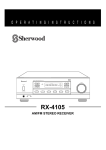
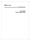
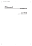
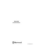
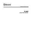
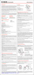
Introduction
READ THIS BEFORE OPERATING YOUR UNIT
This symbol is intended to alert the user to the
presence of uninsulated "dangerous voltage" within
the product's enclosure that may be of sufficient
magnitude to constitute a risk of electric shock to
persons.
CAUTION
: TO REDUCE THE RISK OF ELECTRIC
SHOCK, DO NOT REMOVE COVER (OR
BACK). NO USER-SERVICEABLE PARTS
INSIDE. REFER SERVICING TO QUALIFIED
SERVICE PERSONNEL.
This symbol is intended to alert the user to the
presence of important operating and maintenance
(servicing) instructions in the literature accompanying
the appliance.
WARNING : TO REDUCE THE RISK OF FIRE OR ELECTRIC SHOCK,
DO NOT EXPOSE THIS APPLIANCE TO RAIN OR MOISTURE.
Note to CATV System Installer :
This reminder is provided to call the CATV system installer’s attention to Article 820-40 of the NEC that
provides guidelines for proper grounding and, in particular, specifies that the cable ground shall be
connected to the grounding system of the building, as close to the point of cable entry as pracitcal.
FCC INFORMATION
This equipment has been tested and found to comply with the limits for a Class B digital device,
pursuant to Part 15 of the FCC Rules. These limits are designed to provide reasonable protection
against harmful interference in a residential installation. This equipment generates, uses and can radiate
radio frequency energy and, if not installed and used in accordance with the instructions, may cause
harmful interference to radio communications. However, there is no guarantee that interference will not
occur in a particular installation. If this equipment does cause harmful interference to radio or television
reception, which can be determined by turning the equipment off and on, the user is encouraged to try to
correct the interference by one or more of the following measures:
Reorient or relocate the receiving antenna.
Increase the separation between the equipment and receiver.
Connect the equipment into an outlet on a circuit different from that to which the receiver is connected.
Consult the dealer or an experienced radio/TV technician for help.
Caution : Any changes or modifications in construction of this device which are not expressly approved
by the party responsible for compliance could void the the user’s authority to operate the
equipment.
FOR YOUR SAFETY
Units shipped to the U.S.A and Canada are designed for operation on 120 V AC only.
Safety precaution with use of a polarized AC plug.
However, some products may be supplied with a nonpolarized plug.
U.S.A
CANADA
120 V
CAUTION
: To prevent electric shock, match wide blade of plug to wide slot, fully
insert.
: Pour éviter chocs électriques, introduire la lame la plus large de la
fiche dans la borne correspondante de la prise et pousser jusqu’ au
fond.
ATTENTION
•
•
•
•
•
•
•
•
Avoid high temperatures. Allow for sufficient heat dispersion when installed on a rack.
Keep the set free from moisture, water, and dust.
Do not let foreign objects in the set.
Handle the power cord carefully. Hold the plug when unplugging the cord.
Unplug the power cord when not using the set for long periods of time.
Do not obstruct the ventilation holes.
Do not let insecticides, benzene, and thinner come in contact wth the set.
Never disassemble or modify the set in any way.
2
SAFETY INSTRUCTIONS
1. Read Instructions - All the safety and operating instructions should
be read before the product is operated.
2. Retain instructions - The safety and operating instructions should
be retained for future reference.
3. Heed Warnings - All warnings on the product and in the operating
instructions should be adhered to.
4. Follow Insturctions - All operating and use instuctions should be
followed.
5. Cleaning - Unplug this product from the wall outlet before cleaning.
Do not use liquid cleaners or aerosol cleaners. Use a damp cloth for
cleaning.
6. Attachments - Do not use attachments not recommended by the
product manufacturer as they may cause hazards.
7. Water and Moisture - Do not use this product near water - for
example, near a bath tub, wash bowl, kitchen sink, or laundry tub; in
a wet basement, or near a swimming pool; and the like.
8. Accessories - Do not place this product on an unstable cart, stand,
tripod, bracket, or table. The product may fall, causing serious injury
to a child or adult, and serious damage to the product. Use only with
a cart, stand, tripod, bracket, or table recommended by the
manufacturer, or sold with the product. Any mounting of the product
should follow the manufacturer’s insturctions, and should use a
mounting accessory recommended by the manufacturer.
9. A product and cart combinaion should be moved with care. Quick
stops, excessive force, and uneven surfaces may cause the product
and cart combination to overturn.
10. Ventilation - Slots and openings in
the cabinet are provided for
ventilation and to ensure reliable
operation of the product and to
protect it from overheating, and
these openings must not be
blocked or covered. The openings
should never be blocked by placing PORTABLE CART WARNING
the product on a bed, sofa, rug, or other similar surface. This
product should not be placed in a built-in installation such as a
bookcase or rack unless proper ventilation is provided or the
manufacturer’s intructions have been adhered to.
11. Power Sources - This product should be operated only from the
type of power source indicated on the marking label. If you are not
sure of the type of power supply to your home, consult your product
dealer or local power company. For porducts intended to operate
from battery power, or other sources, refer to the operating
instructions.
12. Grounding or Polarization - This product may be equipped with a
polarized alternating-current line plug (a plug having one blade
wider than the other). This plug will fit into the power outlet only one
way. This is a safety feature. If you are unable to insert the plug
fully into the outlet, try reversing the plug. If the plug should still fail
to fit, contact your electrician to replae your obsolete outlet. Do not
defeat the safety purpose of the polarized plug.
Alternate Warnings - This product is equipped with a three-wire
grounding-type plug, a plug having a third(grounding) pin. This plug
will only fit into a grounding-type power outlet. this is a safety
feature. If you are unable to insert the plug into the outlet, contact
your electrician to replace your obsolete outlet. Do not defeat the
safety purpose of the gronding-type plug.
13. Power-Cord Protection - Power-supply cords should be routed so
that they are not likely to be walked on or pinched by items placed
upon or against them, paying particlar attention to cords at plugs,
convenience receptacles, and the point where they exit from the
product.
14. Outdoor Antenna Grounding - If an outside antenna or cable
system is connected to the product, be sure the antenna or cable
system is grounded so as to provide some protection against
voltage surges and built-up static charges. Article 810 of the
National Electrical Code, ANSI/NFPA 70, provides information with
regard to proper grounding of the mast and supporting structure,
grounding of the lead-in wire to an antenna discharge unit, size of
grounding conductors, location of antenna-discharge unit,
3
connection to grounding electrodes, and requirements for the
grounding electrode. See Figure 1.
Figure 1
Example of antenna grounding as per
National Electrical Code, ANSI/NFPA 70
ANTENNA
LEAD IN
WIRE
GROUND
CLAMP
ANTENNA
DISCHARGE UNIT
(NEC SECTION 810-20)
ELECTRIC
SERVICE
EQUIPMENT
GROUNDING CONDUCTORS
(NEC SECTION 810-21)
GROUND CLAMPS
NEC-NATIONAL ELECTRICAL CODE
POWER SERVICE GROUNDING
ELECRODE SYSTEM
(NEC ART 250, PART H)
15. Lightning - For added protection for this product during a lightning
storm, or when it is left unattended and unused for long periods of
time, unplug it from the wall outlet and disconnect the antenna or
cable system. This will prevent damage to the product due to
lightning and power-line surges.
16. Power Lines - An outside antenna system should not be located in
the vicinity of overhead power lines or other electric light or power
circuits, or where it can fall into such power lines or circuits. When
installing an outside antenna system, extreme care should be taken
to keep from touching such power lines or circuits as contact with
them might be fatal.
17. Overloading - Do not overload wall outlets, extension cords, or
integral convenience receptacles as this can result in a risk of fire
or electric shock.
18. Object and Liquid Entry - Never push objects of any kind into this
product through openings as they may touch dangerous voltage
points or short-out parts that could result in a fire or electric shock.
Never spill liquid of any kind on the product.
19. Servicing - Do not attempt to service this product yourself as
opening or removing covers may expose you to dangerous voltage
or other hazards. Refer all servicing to qualified service personnel.
20. Damage Requiring Service - Unplug this product form the wall
outlet and refer servicing to qualified service personnel under the
following conditions:
a) When the power-supply cord or plug is damaged,
b) If liquid has been spilled, or objects have fallen into the
product,
c) If the product has been exposed to rain or water,
d) If the product does not operate normally by following the
operating instructions. Adjust only those controls that are
covered by the operating instructions as an improper
adjustment of other controls may result in damage and will
often require extensive work by a qualified technician to
restore the product to its normal operation.
e) If the product has been dropped or damaged in any way, and
f) When the product exhibits a distinct change in performance this indicates a need for service.
21. Replacement Parts - When replacement parts are required, be
sure the service technician has used replacement parts specified
by the manufacturer or have the same characteristics as the
original part. Unauthorized substitutions may result in fire, electric
shock, or other hazards.
22. Safety Check - Upon completion of any service or repairs to this
product, ask the service technician to perform safety checks to
determine that the product is in proper operating condition.
23. Wall or Ceiling Mounting - The product should be mounted to a
wall or ceiling only as recommended by the manufacturer.
24. Heat - The product should be situated away from heat sources
such as radiators, heat registers, stoves, or other products
(including amplifiers) that produce heat.
CONTENTS
Introduction
READ THIS BEFORE OPERATING YOUR UNIT................................................................................... 2
SAFETY INSTRUCTIONS ......................................................................................................................... 3
System Connections ....................................................................................................................................... 5
Front Panel & Remote Controls ................................................................................................................. 7
REMOTE CONTROL OPERATION RANGE .......................................................................................... 9
LOADING BATTERIES ............................................................................................................................ 9
Operations
LISTENING TO A PROGRAM SOURCE ............................................................................................... 10
LISTENING TO RADIO BROADCASTS ............................................................................................... 12
RECORDING ............................................................................................................................................ 14
OTHER FUNCTIONS .............................................................................................................................. 14
Troubleshooting Guide ............................................................................................................................... 15
Specifications ................................................................................................................................................. 16
4
System Connections
• Do not plug the AC input cord into the wall AC outlet until all connections are completed.
• Be sure to connect the white RCA pin cords to the L(left) and the red RCA pin cords to the R(right) jacks when making audio
connections.
• Change the position of the FM indoor antenna until you get the best reception of your favorite FM stations.
• A 75 Ω outdoor FM antenna may be used to further improve the reception.
Disconnect the indoor antenna before replacing it with the outdoor one.
• Place the AM loop antenna as far as possible from the receiver, TV set, speaker cords and the AC input cord and set it to a
direction for the best reception.
• If the reception is poor with the AM loop antenna, an AM outdoor antenna can be used in place of the AM loop antenna.
• Make connections firmly and correctly. If not, it can cause loss of sound, noise or damage to the receiver.
• If the electricity fails or the AC input cord is left unplugged for more than 2 weeks, the memorized contents will be cleared.
Should this happen, memorize them again.
PHONO
MADE IN CHINA
DESIGNED IN USA
R
L
SER. NO
L
R
CD
TAPE
A
AUX
L
L
R
R
B
■ CONNECTING AUDIO COMPONENTS
■ CONNECTING ANTENNAS
FM
PHONO
GND
L
CD
FM
B
5
A
R
TAPE
AUX
L
L
R
R
DIGILINK
R
L
R
L
A
B
6
Front Panel & Remote Controls
3
14
12
11
23
7
24
8
9
D A S
DISCRETE AMPLIFIER STAGE
ST TUNED
PRESET
MEM
REMOTE
SENSOR
KHz
MHz
SLEEP
A
5
1
B
6
4
10
17
DIGI LINK III System Remote Controls
POWER ON
POWER ON
4
SPEAKER
STANDBY
1
SPEAKER
A
B
CD
TAPE
APE
DIMMER
SLEEP
AUX
PHONO
REPEAT
REPEA
TUNER
2
19
A
6
CD
INTRO
SL
AUX
PH
REPEAT
TU
TAPE
CD
20
DIMMER
B
• You can remotely control not only this receiver but
also Sherwood compatible components bearing the
DIGI LINK II or III logo.
• For system remote control operation, first make the
DIGI LINK connections.
• In the DIGI LINK III remote control system, if A
pressing PLAY, etc. on CD player or tape deck, CD
B
or TAPE is selected automatically without selecting
the input source and then PLAY, etc. starts.
A/B
21
STAN
A/B
IN
DECK SEL.
A
22
TAPE
DECK SEL.
TREBLE
BASS
B
9-b
+
TREBLE
+
T/P
12
MUTE
17
VOL.
14
TUNE
FM MODE
14
TUNE
MEMO
15
13
Notes:
• Some functions for a CD player or tape deck may
not be available.
• For details about functions, refer to the operating
instructions of each component.
BASS
+
P.SCAN
VOL.
16
1
2
3
4
5
6
7
8
9
0
18
T/P
MUTE
VOL.
TUNE
TUNE
MEMO
FM MODE
P.SCAN
VOL.
11
17
1
2
3
4
5
6
7
8
9
0
REMOTE CONTROL RM-110
REMOTE CONTROL RM-117
7
POWER BUTTON
In the standby mode, press this button, then this unit is
turned on to enter the operating mode.
TUNING/PRESET MODE BUTTON
Press this button to select the tuning mode or the preset
mode.
STANDBY BUTTON
In the operating mode, press this button or the POWER
button on the front panel, then this unit is turned off to
enter the standby mode.
NUMERIC BUTTONS(0 ~ 9)
Press these buttons to select or to store preset stations
directly.
TUNING/PRESET UP/DOWN(
BUTTONS
Press these buttons to tune in the desired stations.
STANDBY INDICATOR
SPEAKER A, B SELECTOR BUTTONS
These buttons allow you to select various combinations of
speakers as follows:
To drive A speakers, press only the SPEAKER A
button (“SPK A” is displayed).
To drive B speakers, press only the SPEAKER B button
(“SPK B” is displayed).
To drive both A and B speakers, press the SPEAKER
A(or B) and B(or A) buttons in order.(“SPK A B” is
displayed).
When using headphones for private listening, press
these buttons in order to switch off the speaker A and B
(“SPK OFF” is displayed).
VOLUME CONTROL KNOB, UP/DOWN(
)
BUTTONS
Adjust the volume to a comfortable listening level with
this knob or these buttons.
HEADPHONE JACK
Stereo headphones with a standard 1/4 inch plug can be
plugged into this jack for private listening.
MUTE BUTTON
Press this button to temporarily mute the sound.
Press again to resume the previous sound level.
INPUT SELECTOR BUTTONS
Press the button to select the desired input source.
DIMMER BUTTON
Press this button to select the brightness of the
fluorescent displays as desired.
Each time this button is pressed, the brightness of all
fluorescent displays changes together as follows:
ON
dimmer
OFF
TONE BUTTON
When adjusting the tone (bass and treble), press this
button to select the desired tone mode.
Each time this button is pressed, the tone mode is
changed to bass or treble.
FM MODE BUTTON
Press this button to select the desired FM mode.
Each time this button is pressed, the FM mode is
changed to the stereo mode or the mono mode.
PRESET SCAN BUTTON
Press this button to scan the stations in the preset sequence.
SLEEP BUTTON
Press this button to activate the sleep timer for a specified
period of time.
Each time this button is pressed, the sleep time changes
as follows:
10
20
30
60
90
OFF
Unit : minutes
BALANCE BUTTON
When adjusting the sound volume balance, press this
button to enter the balance mode.
BALANCE, TREBLE/BASS UP/DOWN
(
) BUTTONS
At the balance mode, adjust the sound volume balance
between left and right speakers with these buttons.
At the desired tone mode, adjust the tone as desired
with these buttons.
CD PLAYER SECTION
- to begin play
- to pause play
REPEAT A/B - to play a specific part repeatedly
,
- to skipping backward or forward
- to stop play
INTRO - to preview each track only for 10 seconds
TONE DIRECT BUTTON
Press this button to listen to a program source without the
tone effect.
MEMORY BUTTON
Press this button to store preset stations.
8
TAPE DECK SECTION
DECK SELECTOR A, B- for selecting deck A or B
, - to begin reverse or forward side playback.
,
- to wind up the tape reversely or forwardly.
- for recording.
- to stop playback or recording.
REMOTE SENSOR
This receives the signals from the remote control unit.
FLUORESCENT DISPLAY
FLUORESCENT DISPLAY
MEMORY INDICATOR
STEREO INDICATOR
TUNED INDICATOR
ST TUNED
PRESET
MEM
KHz
MHz
SLEEP
PRESET NUMBER, SLEEP TIME DISPLAY
INPUT, FREQUENCY, VOLUME LEVEL, OPERATING INFORMATION, etc.
REMOTE CONTROL OPERATION RANGE
LOADING BATTERIES
Remove the cover.
1
D A S
DISCRETE AMPLIFIER STAGE
ST TUNED
PRESET
MEM
REMOTE
SENSOR
KHz
MHz
SLEEP
A
B
POWER ON
STANDBY
SPEAKER
A
B
CD
TAPE
APE
DIMMER
SLEEP
AUX
PHONO
REPEAT
REPEA
TUNER
Load two batteries matching the polarity.
2
A/B
CD
INTRO
A
TAPE
DECK SEL.
B
+
TREBLE
BASS
+
T/P
MUTE
VOL.
TUNE
TUNE
MEMO
FM MODE
+
P.SCAN
VOL.
1
2
3
4
5
6
7
8
9
0
REMOTE CONTROL RM
RM-117
117
(AAA size)
Use the remote control unit within a range of about
7 meters (23 feet) and angles of up to 30 degrees
aiming at the remote sensor.
Remove the batteries when they are not used for a
long time.
Do not use the rechargeable batteries(Ni-Cd type).
9
Operations
LISTENING TO A PROGRAM SOURCE
Turn the power on.
1
• Then this unit is turned on to enter the
operating mode.
• In the operating mode, when the POWER
button on the front panel or the
STANDBY button on the remote control is
pressed, the unit is turned off to enter the
standby mode.
• In the standby mode, the STANDBY
indicator lights up. This means that the
receiver is not disconnected from the AC
mains and a small amount of current is
retained to support the memorized contents
and operation readiness.
STANDBY
POWER ON
STANDBY
ST
ANDBY
STNADBY
POWER ON
SPEAKER
or
A
B
CD
TAPE
DIMMER
SLEEP
AUX
PHONO
REPEAT
TUNER
A/B
CD
INTRO
A
ON/STANDBY
TAPE
DECK SEL.
B
+
TREBLE
BASS
+
T/P
MUTE
VOL.
TUNE
TUNE
MEMO
FM MODE
P.SCAN
VOL.
1
2
3
4
5
6
7
8
9
0
Select the desired input source.
Switch the desired speakers on.
2
3
REMOTE CONTROL RM-117
FM/AM
POWER ON
CD
TAPE
AUX
PHONO
STANDBY
ST
ANDBY
SPEAKER
A
SPEAKER
B
A
B
SPEAKER
A
B
CD
TAPE
APE
DIMMER
SLEEP
AUX
PHONO
REPEAT
REPEA
TUNER
CD
TAPE
AUX
PHONO
POWER ON
TUNER
or
STANDBY
SPEAKER
A
B
CD
TAPE
APE
A/B
DIMMER
SLEEP
AUX
PHONO
REPEAT
REPEA
TUNER
or
A/B
CD
INTRO
CD
INTRO
A
Then the corresponding speaker indication(“SPK
A(or/and) B” is displayed and the sound can be heard
from the speakers connected to the selected speaker
terminals.
When using the headphones for private listening, press
the corresponding SPEAKER button to switch off both
A and B speakers.
DECK SEL.
B
TREBLE
BASS
T/P
MUTE
VOL.
TUNE
TUNE
MEMO
FM MODE
Each time the FM/AM button on the front panel or
the TUNER button on the remote control is pressed,
the band is changed to AM or FM.
P.SCAN
VOL.
POWER ON
STANDBY
SPEAKER
4
Operate the selected component for
playback.
A
B
CD
TAPE
DIMMER
SLEEP
VIDEO
TV/AUX
Adjust the volume to a comfortable
listening level.
REPEAT
TUNER
A/B
INTRO
1
2
3
4
5
6
7
8
9
0
5
A
DECK SEL.
B
VOLUME
+
TREBLE
BASS
+
T/P
TUNE
TUNE
MEMO
FM MODE
DOWN
VOL.
VOL.
or
REMOTE CONTROL RM-117
MUTE
+
P.SCAN
VOL.
UP
VOL.
10
1
2
3
4
5
6
7
8
9
0
REMOTE CONTROL RM-110
POWER ON
STANDBY
SPEAKER
A
B
CD
TAPE
DIMMER
SLEEP
VIDEO
TV/AUX
REPEAT
TUNER
A/B
To mute the sound.
To listen with the headphones.
INTRO
6
7
A
DECK SEL.
B
+
TREBLE
PHONES
BASS
+
T/P
MUTE
MUTE
VOL.
TUNE
TUNE
MEMO
FM MODE
+
P.SCAN
VOL.
“MUTE” lights up and flickers.
To resume the previous sound level, press this button
again.
1
2
3
4
Be sure to switch off both A and B speakers.
POWER ON
STANDBY
5
SPEAKER
6
7
8
9
0
Adjusting the tone(bass and treble)
B
CD
TAPE
DIMMER
SLEEP
VIDEO
TV/AUX
REPEAT
TUNER
At the desired tone mode, adjust the tone
as desired.
A/B
INTRO
REMOTE CONTROL RM-110
9
Enter the tone mode.
8
A
TONE
A
DECK SEL.
B
+
TREBLE
BASS
+
T/P
MUTE
or
TREBLE
+
BASS
VOL.
TUNE
+
TUNE
MEMO
FM MODE
+
P.SCAN
VOL.
If the tone display disappears, start from the step 8
again.
When pressing the TREBLE UP/DOWN(+/-) or
BASS UP/DOWN(+,-) buttons, you need not
select the desired tone mode on the step 8.
Notes:
Extreme settings at high volume may damage your
speakers.
In general, the bass and treble levels are adjusted
to 0.
Each time this button is pressed, the corresponding
tone mode is selected and shown for 3 seconds as
follows:
BASS TRBL
1
2
3
4
5
6
7
8
9
0
REMOTE CONTROL RM-110
Note:
When the tone direct function is activated, the tone
mode cannot be entered and “TON DIR” flickers
for 3 seconds.
To listen to a program source without the tone effect.
10
“TON DIR” is displayed and the sound that
bypasses the tone circuitry will be heard.
To cancel the tone direct function, press this button
again to display “TON CTRL”.
TONE DIRECT
POWER ON
STANDBY
SPEAKER
Adjusting the sound volume balance
A
B
CD
TAPE
DIMMER
SLEEP
VIDEO
TV/AUX
REPEAT
TUNER
Adjust the sound volume balance between
the left and right speakers.
A/B
12
Enter the balance mode.
11
INTRO
A
DECK SEL.
B
TREBLE
BASS
BALANCE
T/P
MUTE
VOL.
TUNE
If the balance display disappears, start from the
step 11 again.
Note:
In general, the balance level is set to 0.
“BAL” and the balance level is displayed for 3
seconds.
TUNE
MEMO
FM MODE
P.SCAN
VOL.
1
2
3
4
5
6
7
8
9
0
REMOTE CONTROL RM-110
11
TREBLE
BASS
LISTENING TO RADIO BROADCASTS
Auto tuning
Select the tuner and then the desired band.
1
POWER ON
STANDBY
ST
ANDBY
SPEAKER
FM/AM
A
B
CD
TAPE
APE
DIMMER
SLEEP
AUX
PHONO
REPEAT
REPEA
TUNER
MHz
TUNER
A/B
CD
or
BAND
• Each time this button is pressed, the band is changed
to FM or AM.
A
TAPE
DECK SEL.
FREQUENCY
INTRO
B
POWER ON
TREBLE
STANDBY
BASS
POWER ON
SPEAKER
T/P
MUTE
A
B
CD
TAPE
DIMMER
SLEEP
VIDEO
TV/AUX
REPEAT
TUNER
TUNE
A/B
TUNE
MEMO
INTRO
2
FM MODE
3
P.SCAN
VOL.
A
DECK SEL.
B
A
B
CD
TAPE
Press the TUNING/PRESET UP(
)
or DOWN(
) button for more than
0.5 second.
T/P
2
+
4
REPEAT
TUNER
INTRO
TAPE
DECK SEL.
BASS
T/P
3
TV/AUX
A/B
B
+
1
VIDEO
A
TREBLE
T/P MODE
MUTE
+
TREBLE
BASS
+
VOL.
5
T/P
or
6
7
8
9
SLEEP
DIMMER
SPEAKER
VOL.
Select the tuning mode.
STANDBY
TUNE
0
TUNE
MEMO
FM MODE
or
+
TUNING/PRESET
P.SCAN
VOL.
TUNE
MUTE
VOL.
TUNE
+
REMOTE CONTROL RM-110
TUNE
• Each time this button is pressed, the mode changes
as follows:
1
2
3
4
5
6
7
8
9
0
TUNE
MEMO
FM MODE
+
P.SCAN
VOL.
• The tuner will now search until a station of
sufficient strength has been found. The display
shows the tuned frequency and “TUNED”.
• If the station found is not the desired one, simply
repeat this operation.
• Weak stations are skipped during auto tuning.
Tuning mode : “PRESET” goes off.
Preset mode : “PRESET” lights up.
REMOTE CONTROL RM-110
1
2
3
4
5
6
7
8
9
0
POWER ON
STANDBY
REMOTE CONTROL RM-110
SPEAKER
A
B
CD
TAPE
DIMMER
SLEEP
VIDEO
TV/AUX
REPEAT
TUNER
A/B
INTRO
Manual tuning
A
TAPE
DECK SEL.
• Manual tuning is useful when you already know the
frequency of the desired station.
• Perform the steps 1 and 2 in “Auto tuning” procedure and
) or DOWN(
)
press the TUNING/PRESET UP(
button repeatedly until the right frequency has been
reached.
B
+
TREBLE
BASS
+
T/P
TUNING/PRESET
or
TUNE
MUTE
VOL.
TUNE
+
TUNE
+
P.SCAN
VOL.
POWER ON
STANDBY
A
SLEEP
DIMMER
SPEAKER
B
Press the MEMORY button.
1 TAPE 2
CD
Presetting radio stations
TUNE
MEMO
FM MODE
6
7
3
VIDEO
4
5
TV/AUX
REPEAT
8
9
0
TUNER
A/B
2
• You can store up to 30 preferred stations in the
memory.
INTRO
REMOTE CONTROL RM-110
A
TAPE
DECK SEL.
B
+
TREBLE
1
Tune in the desired station with auto or
manual tuning.
BASS
+
T/P
MUTE
MEMO
MEMORY
VOL.
TUNE
or
• “MEMO” is flickering for 5 seconds.
TUNE
MEMO
FM MODE
+
P.SCAN
VOL.
1
2
3
4
5
6
7
8
9
0
REMOTE CONTROL RM-110
12
3
Select the desired preset number (1~30)
and press the MEMORY button.
4
Repeat the above steps 1 to 3 to memorize
other stations.
T/P
TUNE
TUNE
MEMO
+
MEMORY
or
+
TREBLE
BASS
+
MUTE
VOL.
TUNE
MEMO
FM MODE
TUNE
+
P.SCAN
VOL.
MEMORY BACKUP FUNCTION
• When using the NUMERIC buttons on the remote
control.
Examples) For “3” : 3
For “15” :
The following items, set before the receiver is turned
off, are memorized.
• INPUT SELECTOR settings
• Preset stations,etc.
Note
• If the electricity fails or the AC input cord is
disconnected for more than 2 weeks, they are all
cleared. So you should memorize them again.
within 2 seconds
1
5
For “30” : 0
• The station has now been stored in the memory.
• When using the NUMERIC buttons, the station is stored
automatically without pressing the MEMO button.
• A stored frequency is erased from the memory by
storing another frequency in its place.
• If “MEMO” goes off, start again from the above step 2.
POWER ON
STANDBY
SPEAKER
A
B
CD
TAPE
DIMMER
SLEEP
VIDEO
TV/AUX
Select the desired preset number.
REPEAT
INTRO
POWER ON
2
STANDBY
After selecting the tuner as an input
source, select the preset mode.
SPEAKER
1
TUNER
A/B
Tuning to preset stations
A
B
CD
TAPE
DIMMER
SLEEP
VIDEO
TV/AUX
REPEAT
TUNER
A
TAPE
DECK SEL.
B
+
TREBLE
BASS
+
T/P
A/B
or
INTRO
TUNING/PRESET
TUNE
MUTE
VOL.
TUNE
+
TUNE
TUNE
MEMO
+
A
TAPE
DECK SEL.
FM MODE
B
+
TREBLE
P.SCAN
VOL.
BASS
+
T/P MODE
T/P
T/P
• When using the NUMERIC buttons on the remote
control.
Examples) For “3” : 3
MUTE
VOL.
or
TUNE
TUNE
MEMO
FM MODE
+
P.SCAN
VOL.
1
2
3
4
5
6
7
8
9
0
POWER ON
STANDBY
SPEAKER
A
B
CD
TAPE
DIMMER
SLEEP
VIDEO
TV/AUX
REPEAT
TUNER
REMOTE CONTROL RM-110
2
3
4
5
6
7
8
9
0
within 2 seconds
For “15” :
1
5
REMOTE CONTROL RM-110
For “30” : 0
• When selecting the desired preset number with the
NUMERIC buttons, the desired preset station will be
tuned to automatically without selecting the preset mode.
POWER ON
• Then “PRESET” lights up.
1
STANDBY
SPEAKER
A
B
CD
TAPE
DIMMER
SLEEP
VIDEO
TV/AUX
REPEAT
TUNER
A/B
A/B
INTRO
INTRO
A
A
Listening to FM stereo broadcasts
Scanning preset stations in sequence
DECK SEL.
DECK SEL.
B
B
TREBLE
• While listening to FM broadcasts,
BASS
TREBLE
T/P
FM MODE
BASS
MUTE
VOL.
TUNE
T/P
TUNE
MEMO
FM MODE
MUTE
VOL.
P.SCAN
VOL.
TUNE
FM MODE
• Each time this button is pressed,
the FM mode changes as follows:
1
2
3
Stereo mode : “ST” lights up.
Mono mode : “ST” goes off.
• When FM stereo broadcasts are poor because of weak
broadcast signals, select the FM mono mode to reduce
the noise, then FM broadcasts are reproduced in
monaural sound.
6
7
8
4
5
9
0
REMOTE CONTROL RM-110
13
TUNE
MEMO
+
P.SCAN
VOL.
1
2
3
4
5
6
7
8
9
0
P.SCAN
• The receiver will start scanning the stations in the preset
sequence.
• At the desired station, press this button again to stop
scanning.
REMOTE CONTROL RM-110
POWER ON
STANDBY
SPEAKER
A
B
CD
TAPE
DIMMER
SLEEP
AUX
PHONO
REPEAT
TUNER
A/B
INTRO
A
DECK SEL.
B
TREBLE
RECORDING
BASS
T/P
MUTE
VOL.
TUNE
TUNE
MEMO
FM MODE
P.SCAN
VOL.
The volume, tone(bass, treble) and balance settings have no effect on the recording signals.
When you select tuner, CD or PHONO as a recording source, recording may be made on TAPE or AUX, or both
simultaneously.
1
6
2
3
4
5
7
8
9
0
REMOTE CONTROL RM-110
Recording with TAPE
1
Select the desired input as a recording
source except for TAPE.
FM/AM
CD
Recording with AUX
AUX
CD
AUX
Select the desired input as a recording
source except for AUX.
1
FM/AM
PHONO
CD
PHONO
TAPE
CD
TAPE
PHONO
POWER ON
POWER ON
TUNER
STANDBY
ST
ANDBY
STANDBY
ST
ANDBY
SPEAKER
A
B
CD
TAPE
APE
DIMMER
SLEEP
AUX
PHONO
REPEAT
REPEA
TUNER
PHONO
TUNER
SPEAKER
or
A
B
CD
TAPE
APE
DIMMER
SLEEP
AUX
PHONO
REPEAT
REPEA
TUNER
or
A/B
A/B
CD
CD
INTRO
INTRO
A
A
TAPE
DECK SEL.
TAPE
DECK SEL.
B
B
TREBLE
TREBLE
BASS
BASS
T/P
T/P
MUTE
MUTE
VOL.
VOL.
TUNE
TUNE
TUNE
MEMO
FM MODE
FM MODE
P.SCAN
VOL.
Start recording on the TAPE.
2
1
2
3
4
5
6
7
8
9
0
TUNE
MEMO
P.SCAN
VOL.
Start recording on the AUX.
2
REMOTE CONTROL RM-110
Start play on the desired input.
1
6
2
3
4
5
7
8
9
0
REMOTE CONTROL RM-110
Start play on the desired input.
3
3
OTHER FUNCTIONS
POWER ON
STANDBY
SLEEP
DIMMER
SPEAKER
Operating the sleep timer
A
B
CD
TAPE
AUX
PHONO
REPEAT
TUNER
Adjusting the brightness of the
fluorescent displays
A/B
INTRO
The sleep timer allows the
system to continue to operate
for a specified period of time
before automatically shutting
off.
To set the receiver to
automatically turn off after
the specified period of time.
A
DECK SEL.
B
TREBLE
BASS
T/P
MUTE
POWER ON
VOL.
TUNE
MEMO
FM MODE
STANDBY
SLEEP
TUNE
2
3
4
5
7
8
9
0
SPEAKER
A
B
CD
TAPE
DIMMER
B
SPEAKER
STANDBY
AUX
TAPE
CD
6
STANDBY
ST
ANDBY
SLEEP
DIMMER
SPEAKER
A
POWER ON
1
POWER ON
P.SCAN
VOL.
DIMMER
SLEEP
AUX
PHONO
REPEAT
REPEA
A
B
CD
TAPE
SLEEP
AUX
PHONO
REPEAT
TUNER
TUNER
A/B
REMOTE CONTROL RM-110
REPEAT
PHONO
DIMMER
A/B
CD
INTRO
CD
INTRO
TUNER
A/B
A
A
INTRO
DECK SEL.
DECK SEL.
B
B
TAPE
A
Each time this button is pressed, the sleep time
changes as follows:
10 20 30 60 90 OFF
DECK SEL.
TREBLE
TREBLE
BASS
B
TREBLE
T/P BASS
MUTE
Unit : minutes
TUNE
VOL.
TUNE
TUNE
MEMO
BASS
MUTE
VOL.
VOL.
T/P
Each time this button is pressed, the brightness of
all fluorescent displays of Sherwood components
connected by the DIGI LINK III changes together
as follows:
ON
dimmer
OFF
T/P
MUTE
FM MODE
TUNE
TUNE
While operating the sleep timer, “SLEEP” lights up.
When the sleep time is selected, all display panels of
Sherwood components connected by the DIGI LINK III
are dimly lit.
MEMO
FM MODE
FM MODE
1
2
3
6
7
8
P.SCAN
VOL.
P.SCAN
VOL.
1
P.SCAN
VOL.
TUNE
MEMO
2
4
6
4
5
8
9
0
1
2
3
4
5
6
7
8
9
0
5
7
9
3
In the display OFF mode, pressing any button will
restore the display ON mode.
0
REMOTE CONTROL RM-110
REMOTE CONTROL REMOTE
RM-117 CONTROL RM-110
14
Troubleshooting Guide
If a fault occurs, run through the table below before taking your receiver for repair.
If the fault persists, attempt to solve it by switching the receiver off and on again. If this fails to resolve the situation, consult
with your dealer. Under no circumstances should you repair the receiver yourself as this could invalidate the warranty.
PROBLEM
POSSIBLE CAUSE
REMEDY
No power
• The AC input cord is disconnected.
• Poor connection at AC wall outlet or the
outlet is inactive.
• Connect the cord securely.
• Check the outlet using a lamp or another
appliance.
No sound
• The speaker cords are disconnected.
• The volume is adjusted too low.
• The MUTE button on the remote control is
pressed to ON.
• Speakers are not switched on.
• Incorrect selection of the input source.
• Incorrect connections between the
components.
• Check the speaker connections.
• Adjust the volume.
• Press the MUTE button to cancel the
muting effect.
• Press the SPEAKER A or B button to ON.
• Select the desired input source correctly.
• Make connections correctly.
Stations cannot be
received
• No antenna is connected.
• The desired station frequency is not tuned
in.
• The antenna is in wrong position.
• Connect an antenna.
• Tune in the desired station frequency.
• An incorrect station frequency has been
memorized.
• The memorized stations are cleared.
• Memorize the correct station frequency.
Poor FM reception
• No antenna is connected.
• The antenna is not positioned for the best
reception.
• Connect an antenna.
• Change the position of the antenna.
Continuous hissing noise
during FM reception,
especially when a stereo
broadcast is received.
• Weak signals.
• Change the position of the antenna.
• Install an outdoor antenna.
Continuous or intermittent
hissing noise during AM
reception, especially at
night.
• Noise is caused by motors, fluorescent
lamps or lightning, etc.
• Keep the receiver away from noise
sources.
• Install an outdoor AM antenna.
No recording
• Incorrect selection between the
components.
• Incorrect operation of each component for
playback and recording.
• Make connections correctly.
Remote control unit does
not operate.
• Batteries are not loaded or exhausted.
• The remote sensor is obstructed.
• Replace the batteries.
• Remove the obstacle.
Other Sherwood components
do not react to remote control
commands.
• DIGI LINK connections are not made
properly.
• Make proper DIGI LINK connections.
Preset stations cannot be
received
15
• Move the antenna and retry tuning.
• Memorize the stations again.
• Operate each component correctly.
Specifications
AMPLIFIER SECTION
Power output, stereo mode, 8 Ω, THD 0.08 %, 20 Hz~20 kHz ................................................................................ 2X100 W
Total harmonic distortion, 8 Ω, 100 W, 20 Hz~20 kHz ................................................................................................ 0.04 %
Intermodulation distortion
60 Hz : 7 kHz= 4 : 1 SMPTE, 8 Ω, 100 W ..................................................................................................................... 0.1 %
Input sensitivity, 47 kΩ
Phono(MM) .................................................................................................................................................................. 2.5 mV
Line(CD,TAPE,AUX) ................................................................................................................................................. 200 mV
Signal to noise ratio, IHF “A” weighted
Phono(MM) .................................................................................................................................................................... 70 dB
Line(CD,TAPE,AUX) .................................................................................................................................................... 95 dB
Frequency response
Phono(MM), RIAA, 30 Hz~20 kHz ........................................................................................................................... 3 dB
Line(CD,TAPE,AUX), 20 Hz~100 kHz ...................................................................................................................... 3 dB
Output level
TAPE/AUX OUT, 2.2 kΩ ........................................................................................................................................... 200 mV
Bass/Treble control, 100 Hz/10 kHz ........................................................................................................................... 10 dB
FM TUNER SECTION
Tuning frequency range .................................................................................................................................... 87.5~108 MHz
Usable sensitivity, THD 3%, S/N 30 dB ....................................................................................................................... 15 dBf
50 dB quieting sensitivity, mono/stereo ............................................................................................................. 25.2/45.2 dBf
Signal to noise ratio, 65 dBf, mono/stereo ................................................................................................................. 68/65 dB
Total harmonic distortion, 65 dBf, 1 kHz, mono/stereo ............................................................................................. 0.5/0.8%
Frequency response, 20 Hz~14 kHz ............................................................................................................................. 3 dB
Stereo separation, 1 kHz ................................................................................................................................................. 40 dB
Capture ratio ...................................................................................................................................................................... 4 dB
IF rejection ratio .............................................................................................................................................................. 80 dB
AM TUNER SECTION
Tuning frequency range .................................................................................................................................... 520~1710 kHz
Usable sensitivity ...................................................................................................................................................... 800 V/m
Signal to noise ratio ......................................................................................................................................................... 40 dB
Selectivity ........................................................................................................................................................................ 25 dB
GENERAL
Power supply ..................................................................................................................................................... 120 V~ 60 Hz
Power consumption ........................................................................................................................................................... 2.5A
Dimensions (W H D) .......................................................................... 440 138 332 mm(17-3/8 5-7/16 13 inches)
Weight (Net) .................................................................................................................................................... 9.0 kg(19.8 lbs)
Note: Design and specifications are subject to change without notice for improvements.
16