1
Scalar AIT 220 Library
Installation and
Operation
Copyright
Copyright 1998 by Advanced Digital Information Corp (ADIC). All rights reserved.
This item and the information contained herein are the property of ADIC. No part of this
document may be reproduced, transmitted, transcribed, stored in a retrieval system, or
translated into any language or computer language in any form or by any means,
electronic, mechanical, magnetic, optical, chemical, manual, or otherwise, without the
express written permission of ADIC, 11431 Willows Road N.E., Redmond, Washington
98052.
Disclaimer
ADIC makes no representation or warranties with respect to the contents of this
document and specifically disclaims any implied warranties of merchantability or fitness
for any particular purpose. Further, ADIC reserves the right to revise this publication
without obligation of ADIC to notify any person or organization of such revision or changes.
Trademark Notices
ADIC™, ADIC Europe™ and Scalar™ are trademarks of Advanced Digital
Information Corporation. Sony® is a registered trademark of Sony Corporation. AIT™,
AME™ and MIC™ are trademarks of Sony Corporation. All other product names are
trademarks or registered trademarks of their respective companies.
Advanced Digital Information Corporation
11431 Willows Road N.E.
Redmond, Washington 98052
62-0152-01
LL
6FDODU$,7
Revision History
Revision
Date
Description
A
December 1998
Initial release for Scalar AIT 220
B
June 1999
AIT-1, AIT-2 tape drives
Revisions to This Manual
This revision of Scalar AIT 220 Library Installation and Operation (B) contains the
following changes and enhancements:
• Added information about Scalar AIT 220’s support for AIT-1 & AIT-2
Tape Drives.
FCC Notice
This equipment has been tested and found to comply with the limits for a Class A digital
device, pursuant to part 15 of the FCC Rules. These limits are designed to provide
reasonable protection against harmful interference when the equipment is operated in a
commercial environment. This equipment generates, uses, and can radiate radio
frequency energy and, if not installed and used in accordance with this instruction
manual, may cause harmful interference to radio communications. Operation of this
equipment in a residential area is likely to cause harmful interference in which case the
user will be required to correct the interference at his own expense.
Shielded cables are required for this device to comply with FCC Rules. Use shielded
cables when connecting this device to others.
Industry Canadian Notice per ICES-003
English This Class A digital apparatus meets all requirements of the Canadian
Interference-Causing Equipment Regulations.
French Cet appareil numérique de la classe A respecte toutes les exigences du
Règlement sur le matériel brouilleur du Canada.
CISPR 22 Compliance Notice
This equipment complies with the CISPR 22B standard for EMI radiation.
,QVWDOODWLRQDQG2SHUDWLRQ
LLL
Product Warranty Caution
The ADIC Scalar AIT 220 Library is warranted to be free from defects in materials,
parts, and workmanship and will conform to the current product specification upon
delivery. For the specific details of your warranty, refer to your sales contract or contact
the company from which the library was purchased.
The warranty for the library shall not apply to failures of any unit when:
• The library is repaired by anyone other than the Manufacturer's personnel
or approved agent.
• The library is physically abused or is used in a manner that is inconsistent
with the operating instructions or product specification defined by the
Manufacturer.
• The library fails because of accident, misuse, abuse, neglect, mishandling,
misapplication, alteration, faulty installation, modification, or service by
anyone other than the factory service center or its approved agent.
• The library is repaired by anyone, including an approved agent, in a manner
that is contrary to the maintenance or installation instructions supplied by
the Manufacturer.
• The Manufacturer's serial number tag is removed.
• The library is damaged because of improper packaging on return.
CAUTION
Returning the library in unauthorized packaging may damage the unit
and void the warranty.
If problems with the library occur, contact your maintenance
organization; do not void the product warranty by allowing untrained
or unauthorized personnel to attempt repairs.
LY
6FDODU$,7
&RQWHQWV
Welcome. . . . . . . . . . . . . . . . . . . . . . . . . . . . . . . . . . . . . . . . . . . . . . . . . . . . . . . vii
About the Scalar AIT 220 . . . . . . . . . . . . . . . . . . . . . . . . . . . . . . . . . . . . . . viii
About this manual . . . . . . . . . . . . . . . . . . . . . . . . . . . . . . . . . . . . . . . . . . . . . xii
Contacting ADIC. . . . . . . . . . . . . . . . . . . . . . . . . . . . . . . . . . . . . . . . . . . . . . xv
1
Installation and Setup. . . . . . . . . . . . . . . . . . . . . . . . . . . . . . . . . . . . . . . . 1
Preparing for installation . . . . . . . . . . . . . . . . . . . . . . . . . . . . . . . . . . . . . . . . .
Installing the library hardware . . . . . . . . . . . . . . . . . . . . . . . . . . . . . . . . . . . .
Configuring the library . . . . . . . . . . . . . . . . . . . . . . . . . . . . . . . . . . . . . . . . .
Checking the setup . . . . . . . . . . . . . . . . . . . . . . . . . . . . . . . . . . . . . . . . . . . .
Where to go from here. . . . . . . . . . . . . . . . . . . . . . . . . . . . . . . . . . . . . . . . . .
2
Library Operation . . . . . . . . . . . . . . . . . . . . . . . . . . . . . . . . . . . . . . . . . 39
Using the operator panel . . . . . . . . . . . . . . . . . . . . . . . . . . . . . . . . . . . . . . . .
Operating in different control modes . . . . . . . . . . . . . . . . . . . . . . . . . . . . . .
Replacing data cartridges . . . . . . . . . . . . . . . . . . . . . . . . . . . . . . . . . . . . . . .
Resetting the library . . . . . . . . . . . . . . . . . . . . . . . . . . . . . . . . . . . . . . . . . . .
3
58
59
61
63
Maintenance . . . . . . . . . . . . . . . . . . . . . . . . . . . . . . . . . . . . . . . . . . . . . . 65
Cleaning requirements. . . . . . . . . . . . . . . . . . . . . . . . . . . . . . . . . . . . . . . . . .
Replacing the fuse . . . . . . . . . . . . . . . . . . . . . . . . . . . . . . . . . . . . . . . . . . . . .
Replacing the air filter . . . . . . . . . . . . . . . . . . . . . . . . . . . . . . . . . . . . . . . . . .
Replacing a tape drive (or drive blank) . . . . . . . . . . . . . . . . . . . . . . . . . . . . .
5
40
45
49
56
Tape Drive Operation . . . . . . . . . . . . . . . . . . . . . . . . . . . . . . . . . . . . . . . 57
Monitoring the tape drive LEDs . . . . . . . . . . . . . . . . . . . . . . . . . . . . . . . . . .
Cleaning the tape drives . . . . . . . . . . . . . . . . . . . . . . . . . . . . . . . . . . . . . . . .
Displaying information about tape drives . . . . . . . . . . . . . . . . . . . . . . . . . .
Ejecting a cartridge manually . . . . . . . . . . . . . . . . . . . . . . . . . . . . . . . . . . . .
4
1
4
28
36
37
66
67
69
71
Shipping the Library . . . . . . . . . . . . . . . . . . . . . . . . . . . . . . . . . . . . . . . 77
Returning the library for service . . . . . . . . . . . . . . . . . . . . . . . . . . . . . . . . . . 77
,QVWDOODWLRQDQG2SHUDWLRQ
Y
Packing the library . . . . . . . . . . . . . . . . . . . . . . . . . . . . . . . . . . . . . . . . . . . . . 78
6
Advanced Operation. . . . . . . . . . . . . . . . . . . . . . . . . . . . . . . . . . . . . . . . 89
Using elements . . . . . . . . . . . . . . . . . . . . . . . . . . . . . . . . . . . . . . . . . . . . . . . . 89
Viewing library information . . . . . . . . . . . . . . . . . . . . . . . . . . . . . . . . . . . . . . 92
Performing diagnostics. . . . . . . . . . . . . . . . . . . . . . . . . . . . . . . . . . . . . . . . . 113
Configuring the serial ports for diagnostics . . . . . . . . . . . . . . . . . . . . . . . . . 122
7
Troubleshooting. . . . . . . . . . . . . . . . . . . . . . . . . . . . . . . . . . . . . . . . . . . 127
Problems with library installation . . . . . . . . . . . . . . . . . . . . . . . . . . . . . . . . 128
Problems with tape drive operation . . . . . . . . . . . . . . . . . . . . . . . . . . . . . . . 130
Problems with library operation . . . . . . . . . . . . . . . . . . . . . . . . . . . . . . . . . . 131
A
Specifications . . . . . . . . . . . . . . . . . . . . . . . . . . . . . . . . . . . . . . . . . . . . . 133
Storage capacities . . . . . . . . . . . . . . . . . . . . . . . . . . . . . . . . . . . . . . . . . . . . .
Overall specifications for the library . . . . . . . . . . . . . . . . . . . . . . . . . . . . . .
Power cord requirements . . . . . . . . . . . . . . . . . . . . . . . . . . . . . . . . . . . . . . .
SCSI terminator specifications . . . . . . . . . . . . . . . . . . . . . . . . . . . . . . . . . . .
SCSI cable specifications . . . . . . . . . . . . . . . . . . . . . . . . . . . . . . . . . . . . . . .
Remote reset cable specifications. . . . . . . . . . . . . . . . . . . . . . . . . . . . . . . . .
B
133
134
135
136
136
137
SCSI Configuration . . . . . . . . . . . . . . . . . . . . . . . . . . . . . . . . . . . . . . . 139
SCSI components . . . . . . . . . . . . . . . . . . . . . . . . . . . . . . . . . . . . . . . . . . . . . 139
Installing the library on the SCSI bus. . . . . . . . . . . . . . . . . . . . . . . . . . . . . . 140
C
Error Codes . . . . . . . . . . . . . . . . . . . . . . . . . . . . . . . . . . . . . . . . . . . . . . 143
D
Sequential Operation . . . . . . . . . . . . . . . . . . . . . . . . . . . . . . . . . . . . . . 153
How sequential operation works . . . . . . . . . . . . . . . . . . . . . . . . . . . . . . . . . 153
Sequential options . . . . . . . . . . . . . . . . . . . . . . . . . . . . . . . . . . . . . . . . . . . . 155
Avoiding interruptions . . . . . . . . . . . . . . . . . . . . . . . . . . . . . . . . . . . . . . . . . 158
Index. . . . . . . . . . . . . . . . . . . . . . . . . . . . . . . . . . . . . . . . . . . . . . . . . . . . . . . . . 159
YL
6FDODU$,7
W
HOFRPH
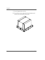
Congratulations on selecting the ADICScalar AIT 220 Library.
Your new library provides unattended data storage, archiving,
backup, and retrieval for mid-range and high-end workstations,
servers, and networks. The robotic cartridge handling mechanism
(CHM) automatically moves cartridges between tape drives and
storage slots, while the tape drives read and write data.
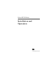
The library is available in standalone (vertical) and rack-mount
(horizontal) models, as shown in the figure.
,QVWDOODWLRQDQG2SHUDWLRQ
YLL
$ERXWWKH6FDODU$,7
The Scalar AIT 220 includes two data cartridge magazines and
either one or two 3.5” form factor Sony AIT tape drives. It can
operate as three SCSI devices on up to three SCSI buses. When the
library is is equipped with AIT-1 drives, the library is a differential
SCSI-2 device and the drives are differential Fast/Wide SCSI-2
devices. When equipped with AIT-2 drives, the library can be
configured as a high voltage differential (HVD) Wide Ultra SCSI
device, or as a low voltage differential (LVD) Wide Ultra SCSI
device.
When operating with two AIT-2 tape drives and assuming an
average data compression ratio of 2:1, the Scalar AIT 220 can store
up to 2.0 terabytes of information on 20 Advanced-Metal
Evaporative (AME) data cartridges (SDX2-50C).
Employing the 3.5” form factor AIT-2 drive, the Scalar AIT 220
provides a maximum sustained data transfer rate of over 720 MB
per minute (assuming 2:1 data compression). The Wide Ultra SCSI
drive does not require periodic head cleaning as often as many
conventioanl tape drives. The drive constantly moinitors head
output to check for possible contamination. If present, the drive
will invoke a built-in Active Head Cleaner. Under extreme
operating conditions, a cleaning cartridge may be required and the
drive indicates this by displaying a Cleaning Request message on
its front panel Status LED.
YLLL
6FDODU$,7
The Sony SDX1-25C, SDX1-35C, SDX2-36C, and SDX2-50C
data cartridges support the Advanced Intelligent Tape format. The
cartridges use a new recording format, Adaptive Lossless Data
Compression (ALDC), Memory In Cassette (MIC) technology
capabilities and use Sony’s AME media, which incorporates dual
cobalt magnetic layers, the absence of binder material to prevent
tape head contamination and a super-durable “diamond-like
carbon” protective coating for extreme durability.
)URQWSDQHOFRPSRQHQWV
S Door and key lock. The front door features a key lock that
enables you to lock the door for data security.
S LCD and keypad (operator panel). The LCD (liquid crystal
display) and keypad allow you to view the operational status
of the library, access a menu of operations, and view status
messages. If necessary, you can tilt the LCD for easier viewing.
,QVWDOODWLRQDQG2SHUDWLRQ
L[
,QWHUQDOFRPSRQHQWV
S Tape drives. The library can include one or two AIT-1 or
AIT-2 tape drives, which are housed in drive carriers.
S Data cartridge magazine(s) and fixed slot. The Scalar AIT
220 includes two removable 10-tape magazines on a rotor. The
fixed slot allows you to store an AIT cleaning cartridge or an
additional AIT data cartridge.
S CHM (cartridge handling mechanism). The CHM is the
robotic assembly that moves cartridges between the storage
locations and the tape drives. The CHM also includes a bar
code scanner, which reads bar code labels affixed to the
cartridges.
[
6FDODU$,7
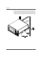
%DFNSDQHOFRPSRQHQWV
S Fan and power entry module. The fan reduces the library's
operating temperature. The power entry module includes the
AC power connector, power switch, and fuse drawer.
S Remote hardware reset port. This port allows you to connect
a remote reset cable for remote resets.
S 9-pin and 25-pin serial ports. Two serial ports allow you to
connect a serial cable and terminal for diagnostics.
S SCSI connectors. The six SCSI connectors (four shown in
illustration) allow you to connect the library to the SCSI bus.
,QVWDOODWLRQDQG2SHUDWLRQ
[L
$ERXWWKLVPDQXDO
Use this manual to install, configure, operate, maintain, and
diagnose problems with the Scalar AIT 220 and its enclosed AIT
tape drives. It includes the following chapters:
S Chapter 1 explains how to install and set up the library.
S Chapter 2 describes how to configure the library.
S Chapter 3 describes how to check your setup.
S Chapter 4 describes basic library operations.
S Chapter 5 describes basic tape drive operations.
S Chapter 6 describes basic maintenance procedures.
S Chapter 7 describes how to move, pack, and ship the library.
S Appendix H provides basic library specifications.
S Appendix I provides SCSI configuration information.
S Appendix J provides LCD error codes.
S Appendix K shows the element indexes for library locations.
A quick reference card is provided at the end of the manual.
Remove this card and keep it near your library. Use the Quick
Reference as a reference for using the operator panel and
interpreting error codes.
[LL
6FDODU$,7
&RQYHQWLRQVXVHGLQWKLVPDQXDO
This manual uses the following conventions:
>(QWHU@
Boxed text indicates keys on the library's operator panel
keyboard.
1RWH Notes provide hints or suggestions about the topic or
procedure being discussed.
³ ,PSRUWDQW
,QIRUPDWLRQQH[WWRWKHZRUG
´,PSRUWDQWµKHOSV\RXFRPSOHWHDSURFHGXUHRU
DYRLGH[WUDVWHSV
&$87,21
%R[HGWH[WXQGHUWKHZRUG´&$87,21µSURYLGHV
LQIRUPDWLRQ\RXPXVWNQRZWRDYRLGGDPDJLQJ
WKHOLEUDU\RUWDSHGULYHVRUORVLQJGDWD
:$51,1*
%R[HGWH[WXQGHUWKHKHDGLQJ´:$51,1*µ
SURYLGHVLQIRUPDWLRQ\RXPXVWNQRZWRDYRLG
SHUVRQDOLQMXU\
,QVWDOODWLRQDQG2SHUDWLRQ
[LLL
5HODWHGSXEOLFDWLRQV
For information about these libraries, the tape drives, and the
standards used by these libraries, refer to the following publications
available from ADIC.
S Scalar AIT 220 Library SCSI Reference, 62-0163-01
[LY
6FDODU$,7
&RQWDFWLQJ$',&
)RUWHFKQLFDOVXSSRUW
$',&7HFKQLFDO
$VVLVWDQFH&HQWHU
$7$&
86
HPDLO
VXSSRUW#DGLFFRP
:RUOG:LGH:HE
KWWSZZZDGLFFRP
%XOOHWLQ%RDUG
%%6
,QWHUQDWLRQDO
&RQQHFWDWXSWREDXGZLWK
GDWDELWVVWRSELWDQGQRSDULW\7XUQ
RQKDUGZDUH576&76IORZFRQWURO
7RRUGHUVXSSOLHVDQGDFFHVVRULHV
$',&6DOHV
ID[
7RUHWXUQHTXLSPHQWIRUVHUYLFH
$',&7HFKQLFDO
$VVLVWDQFH&HQWHU
$7$&
86
HPDLO
VXSSRUW#DGLFFRP
,QVWDOODWLRQDQG2SHUDWLRQ
,QWHUQDWLRQDO
[Y
1RWHV
[YL
6FDODU$,7
1
,QVWDOODWLRQDQG6HWXS
This chapter describes how to install and set up your library.
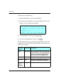
Preparing for installation
This section provides step-by-step instructions for preparing the library.
You can use the table below as a checklist.
✔
Step
Description
1
Unpack the library.
2
Obtain accessories and equipment.
3
Prepare the host computer.
4
Prepare the library for installation.
Step 1 – Unpack the library
Complete the unpacking steps printed on the box. Save all the original
packing materials in case you need to ship or move the library later.
,QVWDOODWLRQDQG2SHUDWLRQ
&KDSWHU
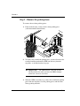
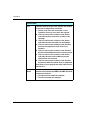
Step 2 – Obtain accessories and equipment
Make certain you have all the accessories and equipment for library
operation, as indicated in the table below. Many of these items are
included in the library accessories box, shipped in a separate box at the
top of the carton.
Required accessories and equipment
Power cord
Included with the library. (Page 135
provides power cord specifications for
other voltages and international use.)
Two keys for front door
Included with the library.
Jumper(s) for connecting the
Included with the library if two tape
library and tape drives to a single drives are installed.
SCSI bus.
Eight 10-32 × 0.5 truss head
screws and clip nuts
Included with rack-mount libraries.
Two slide rails, attached to the
sides of the library
SCSI cables
If these items are not included with the
library, contact ADIC to purchase them.
SCSI bus terminator(s) (required If you want to use your own, see
if the library or one of the tape
Appendix A for specifications.
drives is the last device on the
bus)
AIT data cartridges and cleaning
cartridges
If cartridges are not included with the
library, contact ADIC to purchase them.
If you want to use your own, refer to
page 49 for appropriate data cartridges
and to page 59 for appropriate cleaning
cartridges.
6FDODU$,7
,QVWDOODWLRQDQG6HWXS
Step 3 – Prepare the host computer
Make certain the SCSI host bus adapter card installed in the computer
and the application software are compatible with the Scalar AIT 220.
You can obtain software compatibility information about ADIC
products from ADIC’s internet site (http://www.adic.com).
Note: If your application only supports a single AIT tape drive, you
can run the library in one of the sequential modes (see page 46
and page 153).
You can install the software application on the host computer before or
after library installation. However, if you install the software first, you
may need to reconfigure it for use with the library.
Step 4 – Prepare the library for installation
Prepare the library as follows:
S Ensure that the work area is free from conditions that could cause
electrostatic discharge (ESD). Discharge static electricity from your
body by touching a known grounded surface, such as your
computer's metal chassis.
S Locate an appropriate area for the library. The library must have a
level surface near a readily accessible outlet. (If you have a
standalone library, adjust the feet to make it level.) In addition, there
must be approximately six inches (15 cm) of open area behind the
library for adequate air flow.
,QVWDOODWLRQDQG2SHUDWLRQ
&KDSWHU
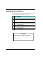
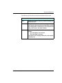
Installing the library hardware
This section provides step-by-step instructions for installing the library
hardware. You can use the table below as a checklist.
✔
Step
Description
1
Install the library into a rack, if you have a rack-mount model.
2
Unlock and open the front door.
3
Remove the packing foam.
4
Prepare and install cartridges.
5
Close and lock the door.
6
Connect the library to the SCSI bus.
7
Connect the power cord.
8
Power on the library.
WARNING!
Before performing any installation or maintenance
procedures, be sure that the library power switch is in the
off position and that the power cord is disconnected from
the library and the outlet.
6FDODU$,7
,QVWDOODWLRQDQG6HWXS
Step 1 – Install the library into a rack
If you have a rack-mount library, follow these instructions to install the
library into a standard EIA 19-inch rack.
WARNING!
Depending on the number of drives installed, the
rack-mount library weighs 50 – 70 pounds (27.2 – 31.8
kg); the standalone library weighs 70 – 90 pounds (31.8 –
40.9 kg). At least 2 people are needed to move or lift the
library. Most of the weight is toward the back of the library.
Make sure you install the rack-mount library in the lowest
possible location in the rack. For best results, use a rack
with extension support legs.
For this procedure, you will need the following:
S Standard EIA 19-inch rack
S TORX screwdriver with T-25 bit
S T-15 bit, if you need to extend the rails
S Eight 10-32 × 0.5 truss head screws (provided in the accessory box)
S Eight clip nuts (provided in the accessory box), necessary if the rack
does not have threaded holes
,QVWDOODWLRQDQG2SHUDWLRQ
&KDSWHU
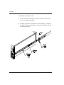
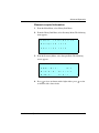
To install the library into a rack:
1. Locate the slide rail assembly attached to each side of the library
chassis, as shown in the figure.
2. Slide the rack-slide rail toward the rear of the library, as shown in
the figure. Press the spring clips to remove the rack-slide rail from
the chassis-slide rail.
6FDODU$,7
,QVWDOODWLRQDQG6HWXS
3. Locate the mounting holes on the rack where you want to install the
library. Allow 1½ inches (3.8 cm) minimum clearance below the
bottom mounting hole.
Note: If the rack does not have threaded holes, attach the clip nuts
provided with the library over the mounting holes, as shown
in the figure.
clip nutssliclip nuts
,QVWDOODWLRQDQG2SHUDWLRQ
&KDSWHU
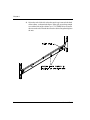
4. Orient the rack-slide rails so that the metal stop is towards the back
of the cabinet, as shown in the figure. If the rails are not long enough
to reach the back of the cabinet, use a T-15 TORX driver to loosen
the nuts on the rails. Extend the rails to the desired length and tighten
the nuts.
6FDODU$,7
,QVWDOODWLRQDQG6HWXS
5. Using a T-25 TORX driver and four screws per rail, attach (but do
not tighten) the rack slide rails to the mounting holes on the rack, as
shown in the figure on page 7.
6. Adjust the distance between the rail brackets on each side of the
cabinet to 17 5/8 inches (44.75 cm). Measure both the front and back.
7. Use a T-25 TORX screwdriver to tighten the screws to
12.0 inch-pounds (13.8 kg-cm) of torque.
,QVWDOODWLRQDQG2SHUDWLRQ
&KDSWHU
8. Using two people to lift it, slide the library into the rack by inserting
the chassis slide rails into the rack slide rails, as shown in the figure.
Press the spring clips while pushing the library firmly into the rack.
When the library is seated properly, you will hear the latch engage.
6FDODU$,7
,QVWDOODWLRQDQG6HWXS
Step 2 – Unlock and open the front door
To open the front door, insert the key from your accessory kit into the
lock, push in, and turn the key one-quarter turn to the right. Pull open
the door.
,QVWDOODWLRQDQG2SHUDWLRQ
&KDSWHU
Step 3 – Remove the packing foam
To remove the two foam packing pieces:
1. From inside the door, remove the first foam packing piece
(rack-mount model shown below).
2. To remove the second foam packing piece, you must first move the
cartridge handling mechanism (CHM) out and away from the
magazine, as described on the next page.
➤ Important
The CHM contains a bar code scanner.
Do not touch the lens when you move the CHM. Smudges
on the lens can cause scan errors.
3. When the CHM is out of the way, remove the second foam packing
piece from the magazine. Save the packing pieces with the other
library packing materials.
6FDODU$,7
,QVWDOODWLRQDQG6HWXS
Rack-mount model:
➊ Pull firmly on the upper
portion of the CHM to slide it
back (toward you). Do not pull
on the CHM base.
➋ Push against the CHM
base, sliding it firmly to the
right or left.
Standalone model:
➊ Pull firmly on the upper
portion of the CHM to slide it
back (toward you). Do not pull
on the CHM base.
➋ Push against the CHM
base, sliding it firmly to the top
or bottom.
,QVWDOODWLRQDQG2SHUDWLRQ
&KDSWHU
Step 4 – Prepare and install cartridges
Four types of AIT data cartridges are available: SDX1-25C, SDX1-35C,
SDX2-36C and SDX2-50C. The SDX1-25C and SDX2-36C are 170
meters in length, while the SDX1-35C and SDX2-50C are 230 meters
in length and all use Sony’s Advanced-Metal Evaporated (AME) tape.
All cartridges employ MIC technology, which incorporates a Flash
memory IC inside the data cartridge, allowing the architecture to capture
various system and user-related statistics directly within the MIC
structure to enhance data reliability, error prediction and successful
performance.
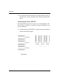
AIT barcode labels (see following illustration) must conform to the
Industry Standard Code 39 (3 of 9 code). Labels which meet the
requirements of ANSI MH10.8M-1983 must be used. They must contain
four to six alphanumeric characters plus a modulus 43 check character
on an 0.40-inch by 2.175-inch label. The barcode and numerics should
be centered horizontally. The narrow elements should be 0.015 +/- 0.004
inches (0.38 0.10mm), and the wide elements 0.030 +/- 0.004 inches
(0.76 0.10 mm). There must be a minimum of 0.2 inches of white space
at each end of the label. Use of a higher density is not recommended. If
a human readable label is not required, the barcode may extend across
the entire width of the label. Failure to comply with this specification
may affect reliability.
6FDODU$,7
,QVWDOODWLRQDQG6HWXS
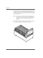
To prepare and install cartridges:
Your library is equipped with a bar code scanner. You can affix bar code
labels to the cartridges. To do this, position the label using the ridge on
the cartridge for guidance. Make sure you orient the label correctly, as
shown in the following illustration.
➤ Important
If you remove a bar code label from a data
cartridge without replacing it, make sure you clean the
label area thoroughly. Bar code labels can leave adhesive
on the label area, which may cause the data cartridge to
stick to the gripper.
,QVWDOODWLRQDQG2SHUDWLRQ
&KDSWHU
4. Make sure the write-protect switches on the cartridges are set
correctly, as shown in the following figure. You can use a ball-point
pen or similar instrument to set the write-protect switch. If the orange
tab fills the window, the cartridge is write-protected.
6FDODU$,7
,QVWDOODWLRQDQG6HWXS
5. Remove the cartridge magazine (shown in the following figure). For
rack-mount models, pull it out first from the right, then the left; for
standalone models, pull it out first from the top, and then bottom.
Access the back magazine by turning the rotor manually.
CAUTION
Make sure the CHM and its cabling are safely out
of the way before you remove or install a cartridge
magazine. If the CHM is blocking the magazine,
move it by following the instructions on page 13.
,QVWDOODWLRQDQG2SHUDWLRQ
&KDSWHU
6. Place the magazine on its feet with the single mounting guide toward
the right. Position each cartridge so that the bar code label is on top
and the write-protect switch is toward the front. Insert the cartridge
into the magazine slot.
Note: Very little force is needed to install a data cartridge. If it
does not snap into place easily or if it protrudes further than
the magazine’s center rib, check the orientation of the
cartridge.
7. To re-install the magazine, follow the instructions below. You can
access the back magazine by turning the rotor manually.
6FDODU$,7
,QVWDOODWLRQDQG6HWXS
8. The library contains one fixed cartridge slot for a cleaning cartridge
or an additional data cartridge. If desired, install a cleaning cartridge
in the fixed cartridge slot, as shown on the following page.
➤ Important
Use only a Sony SDX-TCL cleaning
cartridge.
,QVWDOODWLRQDQG2SHUDWLRQ
&KDSWHU
Rack-mount model:
Position the cleaning cartridge
so that the window showing
the tape reels is to the right and
snap the cartridge into place.
Standalone model:
Position the cleaning cartridge
so that the window showing
the tape reels is to the top and
snap the cartridge into place.
6FDODU$,7
,QVWDOODWLRQDQG6HWXS
Step 5 – Close and lock the door
Close the door and turn the key a quarter-turn to the left.
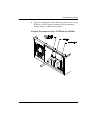
Step 6 – Connect the library to the SCSI bus
This section provides general guidelines for connecting the library to the
SCSI bus. The library consists of three SCSI devices: the library itself
and the two tape drives. If a drive blank is installed, the library consists
of two SCSI devices (the drive blank is not addressable).
Before you begin
1. Make certain the host computer and any peripheral devices are
turned off.
CAUTION
To avoid damaging the tape drives, make sure the tape
drives and library are powered off when you connect
the library to the SCSI bus.
2. If you are unfamiliar with connecting devices on a SCSI bus, first
read Appendix B.
3. Determine the SCSI bus configuration (that is, how many SCSI
buses you will connect to the library and which bus you will connect
to which device).
4. If you are connecting the library and two tape drives to a single bus,
install a jumper over the two inside connectors, as shown in the
example.
,QVWDOODWLRQDQG2SHUDWLRQ
&KDSWHU
5. For each device that terminates the bus (either the library or one of
the tape drives), install a terminator on one of the connectors for that
device.
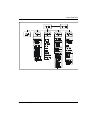
Connecting the Scalar AIT 220
The Scalar AIT 220 can operate on one, two, or three SCSI buses. The
library, Drive 1, and Drive 2 can operate on separate SCSI buses or on
the same SCSI bus.
1. Connect the library to the SCSI bus, using the connector assignments
shown in the following figure.
6FDODU$,7
,QVWDOODWLRQDQG6HWXS
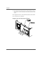
2. If you are connecting the library and two tape drives to one or two
SCSI buses, install a jumper (or jumpers) over the connectors
between devices, as shown in the example.
Example: Six-connector Scalar AIT 220 on one SCSI bus
,QVWDOODWLRQDQG2SHUDWLRQ
&KDSWHU
3. For each device that terminates the bus (either the library or one of
the tape drives), install a terminator on one of the connectors for that
device.
The example below shows a Scalar AIT 220 connected to three SCSI
buses. All the buses are terminated.
Example: Scalar AIT 220 on three SCSI buses
6FDODU$,7
,QVWDOODWLRQDQG6HWXS
Step 7 – Connect the power cord
➤ Important
The power cord shipped with the library
is a 120 VAC three-conductor power cord for use in the
United States and Canada. If you are planning to use an
input voltage other than 120 volts AC or if you plan to use
the library outside of the United States or Canada, you
must supply your own power cord. Refer to page 135 for
more information.
1. Make sure that the power switch on the back of the library is off (the
0 is pressed).
,QVWDOODWLRQDQG2SHUDWLRQ
&KDSWHU
2. Connect the female end of the power cord to the power connector
on the back of the library.
3. Plug the male end of the power cord into the power source.
Note: The library has autoranging voltage selection, so you do not
need to change the voltage setting.
Step 8 – Power on the library
1. Make certain the library's door is closed and locked.
2. Turn on the host computer system.
Note: If your host system requires that attached peripheral devices
be powered on before the host, turn on the library before
you turn on the host.
3. Push the power switch on the back of the library to the on position
(the I is pressed).
Wait while the library performs its power-on sequence. During this time,
the following activities occur:
S The cooling fan begins to rotate.
S The LCD illuminates and displays the Main Screen.
S Each tape drive and the library perform a power-on self-test.
6FDODU$,7
,QVWDOODWLRQDQG6HWXS
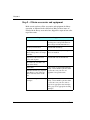
If problems occur . . .
If the library does not
power on as described:
Check the following:
S Is the power switch on (1 is pressed)?
S Is the power cord inserted correctly?
S Is the library door closed and locked?
S Is the SCSI bus terminated?
S Is the SCSI cable connected to the
library and host computer?
S Is the host computer system turned on?
For additional troubleshooting tips, see
“Problems with library installation” on
page 128.
If an error code is displayed See Appendix J for a list of error codes and
on the LCD:
corrective actions.
If you cannot solve the
problem yourself:
,QVWDOODWLRQDQG2SHUDWLRQ
Contact your service provider or ADIC.
&KDSWHU
Configuring the library
Configuration steps include:
S
S
S
S
Displaying the Configuration Menu
Setting SCSI IDs
Setting LCD security (optional)
Setting other configuration options (if necessary)
To change options, you will use the operator panel (LCD and keypad)
on the front of the library, as shown in the figure. If desired, you can tilt
the LCD for easier viewing.
6FDODU$,7
,QVWDOODWLRQDQG6HWXS
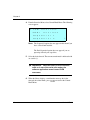
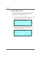
Step 1 – Display the Configuration Menu
To display the Configuration Menu:
1. Access the Main Menu by pressing >(VFDSH@ on the keypad. The Main
Menu is shown.
→M a i n
S c r e e n
I n t e r
C o n f
f a c e
M e n u
i g u r a t
i o n
M a i n t e n a n c e
M e n u
M e n u
↓
2. Press >@ to scroll down to Configuration Menu. Then press >(QWHU@.
The Configuration Menu displays:
→S e t
S C S I
,QVWDOODWLRQDQG2SHUDWLRQ
S C S I
P a r
I D s
i
t y
O N
S e q u e n t
i a l
O p t
i o n s
A d j u s t
C o n t
r a s t
↓
&KDSWHU
During library configuration, use the operator keys for the following
functions:
To select an item from a menu: Press >@ or >@ to scroll up and down
through the items. When the screen
arrow (→) points to the desired item,
press >(QWHU@.
To move the screen arrow left
and right, or toggle some
options:
Press >@ or >@.
To return to a previous screen Press >(VFDSH@.
or cancel the operation without
saving:
To redisplay the Main Screen: Select Main Screen (the first item in the
Main Menu) and press >(QWHU@.
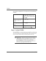
Step 2 – Set the SCSI IDs
Default SCSI IDs are assigned at the factory for the library and each tape
drive. Drive blanks are assigned B (for blank). This section describes
how to view the default settings and change them if necessary.
➤ Important
The library and tape drives must each have
a unique SCSI ID within each SCSI bus. Because you may
have multiple buses, the library does not check for
duplicate SCSI IDs. It is your responsibility to make sure
you do not assign duplicate IDs within a bus.
6FDODU$,7
,QVWDOODWLRQDQG6HWXS
To view or change the SCSI IDs:
1. From the Configuration Menu, select Set SCSI IDs. The following
screen appears:
S C S I
D 2
D 1
I D s :
3
2
L I B
1
¦
↓
→
2. To set the SCSI ID for Drive 2 (farthest from the magazine), press
>@ or >@ until the screen displays the correct SCSI ID.
3. Press >@ to move the screen arrows to Drive 1.
4. To set the SCSI ID for Drive 1 (closest to the magazine), press >@
or >@ until the screen displays the correct SCSI ID.
5. Press >@ to move the screen arrows to LIB.
6. To set the SCSI ID for the library, press >@ or >@ until the screen
displays the correct SCSI ID.
7. When the SCSI IDs for both tape drives and the library are correct,
press >(QWHU@to accept your choices.
8. If you have changed one or more of the tape drive IDs, the system
displays a confirmation message. Press >(QWHU@. The system resets the
tape drives with changed IDs and returns you to the Configuration
Menu.
,QVWDOODWLRQDQG2SHUDWLRQ
&KDSWHU
Step 3 – Set security
The Security option allows you to prevent unauthorized personnel from
disrupting the operation of the library. When you enable security, the
following activities are prevented:
S
S
S
S
S
S
S
S
S
Changing SCSI IDs
Changing SCSI parity checking
Changing the control mode
Changing the library serial number
Using the Diagnostics Menu and the Demo Menu
Using the Clean Drives Menu
Opening the front door (operator panel security only)
Changing the installed tape drive model
Communicating with a tape drive across a serial port
If you attempt to perform any of the above operations when security is
enabled, the library displays a message that states security is active. The
message also states whether security was enabled from the operator
panel or by the application with a SCSI command.
Methods for enabling and disabling security
Security can be enabled or disabled in either of two ways:
S You can set the security option from the operator panel using the
Configuration Menu, as described in this section.
S The application software can issue a SCSI MODE SELECT
command to turn security on or off (see your software
documentation or the Scalar AIT 220 Library SCSI Reference).
6FDODU$,7
,QVWDOODWLRQDQG6HWXS
Whichever method is used to enable security (operator panel or SCSI)
must also be used to disable security. That is, if you enable security from
the operator panel, you must disable it from the operator panel. If security
is enabled by the application (SCSI), it must be disabled by the
application.
Note: To determine if security has been set by your application, look
at the SCSI Mode Parameters screen (see page 93).
Security remains in effect across resets.
Enabling security from the operator panel
1. From the Configuration Menu, select Set Security On. The following
screen appears:
S e t
S e c u r
E n t e r
i
t y
P a s s w o r d
0 0 0
↑
T h e n
P r e s s
O n :
E n t e r
→
Note: If the menu displays Set Security Off, the security option
has already been enabled.
2. Select a three-digit password. Press >@ and >@ to move from column
to column and >@ and >@ to change the numbers. (The default
password is 000.) When you are finished, press >(QWHU@.
➤ Important
You must use the same password to turn
security off.
3. A confirmation message appears. Press >(QWHU@. Or, to exit without
saving the password, press >(VFDSH@.
,QVWDOODWLRQDQG2SHUDWLRQ
&KDSWHU
Disabling security from the operator panel
1. From the Configuration Menu, select Set Security Off. The
following screen appears:
S e t
S e c u r
E n t e r
i
t y
P a s s w o r d
f
:
0 0 0
↑
T h e n
P r e s s
O f
E n t e r
→
Note: If the menu displays Set Security On, the LCD security
function is disabled. However, security may have been
enabled by your application using a SCSI command. If so,
it must be disabled by your application. Refer to your
software documentation.
2. To specify the three-digit password, press >@ and >@ to move from
column to column and >@ and >@ to change the numbers. When you
are finished, press >(QWHU@.
If you enter the wrong password, the system displays an error message.
If You Forget the Password
Try entering the default password
(000). If the default password has been changed and you do not know
what it is, call your service provider.
6FDODU$,7
,QVWDOODWLRQDQG6HWXS
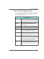
Step 4 – Set other configuration options
The Configuration Menu contains some other configuration options for
the library, as described in the table below. If desired, you can check
these settings and change them.
Configuration options
SCSI Parity*
Allows you to enable parity checking for the library (if
the SCSI adapter card connected to the library supports
it). When enabled, the library checks all data on the SCSI
bus for parity. This remains in effect across power cycles.
Sequential
Options
Provides options for using the library’s sequential
modes. (See page 46 and Appendix K for more
information.)
Adjust Contrast
Controls the brightness of the lettering on the LCD.
Back Light
Turns the LCD background on or off.
Set Date
Allows you to set the system date for the library. The date
appears on the Command History screen and on
diagnostic listings (see Chapter 6 for more information).
Set Time
Allows you to set the time that is shown on the library's
Main Screen and in the Command History screen (see
Chapter 6 for more information).
Set Serial Number Allows you to make certain the serial number label on
the back of the library is also displayed in this screen;
and allows you to change the serial number. (The serial
number entered in this screen appears on diagnostic
listings; see Chapter 6 for more information.)
Use AIT
,QVWDOODWLRQDQG2SHUDWLRQ
Allows you to check whether an AI-T1 drive is installed.
This option is set at the factory. Note: If you want to
upgrade from an AIT-1 to an AIT-2 tape drive, contact
ADIC.
&KDSWHU
* Parity checking for the library can also be enabled by the application software using
the SCSI command, MODE SELECT. The method used last to set parity checking
(LCD or SCSI command) has precedence. Parity checking for tape drives is set
separately.
Checking the setup
After installing the hardware and software, check the setup by
performing some exercises on the library, as described below. (While
these exercises are not required, it is a good idea to verify that your
software and hardware are properly communicating before you begin
operations.)
S Use the options on the Diagnostic Menu to exercise the hardware.
This determines whether the library hardware components are
operating properly. See page 117 for more information about library
diagnostics.
S Instruct the application software to load some cartridges into the tape
drive. This determines whether the software and library are
communicating properly.
S Back up several megabytes of data and perform a comparison check
on the backed up data. (If you have two tape drives, back up several
megabytes to both.) This determines whether the software and tape
drives are communicating properly.
6FDODU$,7
,QVWDOODWLRQDQG6HWXS
If problems occur . . .
If the library and tape drive
are not operating as
expected:
See Chapter 7 for troubleshooting
information.
If there is an error code
displayed on the LCD:
See Appendix J for a list of error codes
and corrective actions.
If you cannot solve the
problem yourself:
Contact your service provider or ADIC.
Where to go from here
Before you begin library operations, check the following:
•
A cartridge magazine is installed.
•
The CHM gripper does not contain a cartridge.
•
The library door is closed and locked.
•
The library is in the proper control mode. The standard operating
mode is SCSI (see page 45).
,QVWDOODWLRQDQG2SHUDWLRQ
&KDSWHU
1RWHV
6FDODU$,7
/LEUDU\2SHUDWLRQ
Once the library and application software are installed and configured,
you can automatically perform backup and restore operations using the
application software. You do not need to intervene in the cartridge
processing during normal library operations.
This chapter describes library operations you may occasionally need to
perform:
S
S
S
S
Using the operator panel
Operating the library in different control modes
Replacing data cartridges
Resetting the library
,QVWDOODWLRQDQG2SHUDWLRQ
&KDSWHU
8VLQJWKHRSHUDWRUSDQHO
The library includes a four-line LCD and keypad, called the operator
panel, which allows you to interactively control library operations.
Using the operator panel, you can set library options, check operating
statistics, and diagnose errors. If desired, you can tilt the LCD for easier
viewing.
0DLQ6FUHHQ
The Main Screen appears when you apply power to the library. The first
and second lines on the Main Screen identify the product name, firmware
version, and time. The third and fourth lines display status information
about the library or tape drive; and if a hardware error occurs, these lines
display information about the error.
6FDODU$,7
/LEUDU\2SHUDWLRQ
An example of the Main Screen with a status message is shown below.
A D I C
V E R
2 2 0
3 . 1 . 1 3
1 2 : 1 5 : 3 7
S t a t u s :
M o v e
1 - D R I V E
P i c k i n g
F r o m
S l o t
1
1RWH The exact wording of the Main Screen may be different on your
screen.
(UURUFRGHV
If a hardware error occurs, an error code will appear automatically on
the third and fourth lines of the Main Screen. You must correct the error
before operation can continue. (Refer to Appendix J for help in
diagnosing and correcting errors.)
The third line provides the error's numerical code; the fourth line
provides a brief explanation of the error.
A D I C
V E R
3 . 1 . 1 3
S t a t u s :
S O U R C E
,QVWDOODWLRQDQG2SHUDWLRQ
2 2 0
E r
1 2 : 1 5 : 3 7
r o r
1 1
E M P T Y
&KDSWHU
0DLQ0HQX
To access the Main Menu, press >(VFDSH@ from the Main Screen. The Main
Menu is shown below:
→M a i n
S c r e e n
I n t e r
C o n f
f a c e
i g u r a t
M e n u
i o n
M a i n t e n a n c e
M e n u
M e n u
↓
The selections on the Main Menu are described in the following table.
The menu structure is shown on the next page.
0DLQ0HQXVHOHFWLRQV
0DLQ
6FUHHQ
5HWXUQVWRWKH0DLQ6FUHHQ
,QWHUIDFH
0HQX
$OORZV\RXWRVSHFLI\KRZ&+0PRWLRQLV
FRQWUROOHGDQGWRFRQILJXUHWKHVHULDOSRUWV
&RQILJXUDWLR
Q0HQX
$OORZV\RXWRVHW6&6,,'VVHFXULW\DQG
RWKHUFRQILJXUDWLRQRSWLRQV
0DLQWHQDQFH $OORZV\RXWRFOHDQWKHWDSHGULYHDQG
0HQX
SHUIRUPGLDJQRVWLFV
/LEUDU\
,QIRUPDWLRQ
0HQX
3URYLGHVWDSHGULYHVWDWXVLQIRUPDWLRQDQG
GLDJQRVWLFLQIRUPDWLRQIRUVHUYLFH
WHFKQLFLDQV
6FDODU$,7
/LEUDU\2SHUDWLRQ
,QVWDOODWLRQDQG2SHUDWLRQ
&KDSWHU
2SHUDWRUNH\V
Use the keys on the operator panel to perform the following actions:
>@
>@
>@>@
>+HOS@
>(VFDSH@
6FUROOVWKHVFUHHQDUURZ→XSRUGRZQ7KH
VFUHHQDUURZSRLQWVWRWKHFXUUHQWVHOHFWLRQ
,QVRPHVFUHHQVPRYHVWKHVFUHHQDUURZOHIWRU
ULJKW2QVRPHPHQXVHOHFWLRQVWRJJOHVDQRSWLRQ
RQRURII
'LVSOD\VWKH+HOSVFUHHQ7RH[LW+HOSSUHVV
[Escape]
5HWXUQVWRWKHSUHYLRXVPHQXRUVFUHHQFDQFHOV
DQRSHUDWLRQZLWKRXWVDYLQJFKDQJHVRULIWKH
0DLQ6FUHHQLVGLVSOD\HGJRHVWRWKH0DLQ0HQX
>(QWHU@
6HOHFWVWKHLWHPQH[WWRWKHVFUHHQDUURZRU
DFFHSWVDFKDQJH
>5HVHW@
'LVSOD\VWKH5HVHWVFUHHQZKLFKDOORZV\RXWR
UHVHWWKHOLEUDU\6HHSDJH IRUPRUH
LQIRUPDWLRQ
6FDODU$,7
/LEUDU\2SHUDWLRQ
2SHUDWLQJLQGLIIHUHQWFRQWUROPRGHV
To determine which interface will control CHM motion, you can set the
library to one of the following control modes:
S
S
S
S
S
S
SCSI Interface
Sequential 1
Sequential 2
Dual Sequential
LCD Interface
25/9-Pin
These control modes allow you to operate the library with the application
software (SCSI Interface), operate the library as a sequential stacker
device (Sequential 1, Sequential 2, Dual Sequential), or perform
diagnostic functions on the library (LCD Interface, 25/9-Pin).
Refer to the following section for control mode descriptions. Refer to
page 47 for instructions on changing the control mode.
1RWH Control mode settings remain through power cycles.
,QVWDOODWLRQDQG2SHUDWLRQ
&KDSWHU
&RQWUROPRGHGHVFULSWLRQV
6&6,,QWHUIDFHPRGH
If you want the application software to control library operations, you
must set the library to SCSI Interface mode. In this standard operating
mode, the application software controls the motion of the CHM by
issuing SCSI commands across the SCSI bus.
1RWH The application software can issue commands to the library
regardless of the control mode. However, the library must be in
SCSI Interface mode for the application software to control
CHM motion.
For detailed information about SCSI commands, refer to the Scalar AIT
220 Library SCSI Reference Manual.
6HTXHQWLDOPRGHV
If you want the library to run as a sequential stacker device, you can set
the library to one of three sequential modes:
S Sequential 1
S Sequential 2
S Dual Sequential
In these modes, the application software does not need to provide support
for library functions, only for the tape drives. For detailed information
about the sequential modes, see Appendix K.
6FDODU$,7
/LEUDU\2SHUDWLRQ
/&',QWHUIDFHPRGH
If you want to perform any operations from the operator panel that
involve moving the CHM, you need to set the library to LCD Interface
mode. All of these operations, such as cleaning the tape drives and
performing diagnostics, are included under the Maintenance Menu.
1RWH LCD Interface mode is required only when you want to control
the motions of the CHM. For example, you do not need to switch
control modes to access the menus.
3LQPRGH
When the library is operating in 25/9-Pin mode, you can control the
motions of the CHM from a remote console program connected to the
library's 9-pin or 25-pin port.
1RWH Use 25/9-Pin mode to control CHM motion only. You do
not need to change the control mode to access a tape drive's
firmware.
For more information about how to use the 25-pin and 9-pin serial ports,
see page 47.
&KDQJLQJWKHFRQWUROPRGH
Make certain the library is in the ready state (for example, no
hardware errors, the door is closed, and so on).
If the security option has been enabled, disable it (see page 32).
From the Main Menu, select Interface Menu.
,QVWDOODWLRQDQG2SHUDWLRQ
&KDSWHU
From the Interface Menu, select Control Mode Menu. The following
screen appears:
→
L C D
I n t e r
* S C S I
f a c e
I n t e r
f a c e
S e q u e n t
i a l
1
S e q u e n t
i a l
2
↓
1RWH The Sequential 2 option does not appear in this menu if you
have a drive blank installed.
The Dual Sequential option does not appear if you are
operating with only one tape drive.
Select the desired mode. The current control mode is indicated with
an asterisk (*).
³ ,PSRUWDQW
:KHQWKHOLEUDU\LVLQ/&',QWHUIDFH
PRGHRULQRQHRIWKHVHULDOSRUWPRGHVWKH
VRIWZDUHDSSOLFDWLRQFDQQRWFRQWURO&+0
PRYHPHQW
When the library displays a confirmation message that it has
changed the control mode, press >(VFDSH@ to return to the Control
Mode Menu.
6FDODU$,7
/LEUDU\2SHUDWLRQ
5HSODFLQJGDWDFDUWULGJHV
This section describes how to:
S
S
S
S
Select the appropriate data cartridges for your tape drive
Open the library door to access the cartridges
Replace a single cartridge or a cartridge magazine
Store cartridges outside the library
6HOHFWLQJGDWDFDUWULGJHV
ADIC strongly recommends that you use Sony® data-grade media with
your AIT tape drives. Sony media meets specifications that are the most
stringent in the industry.
&$87,21
1HYHUXVHYLGHRJUDGHWDSHIRUGDWDVWRUDJH
9LGHRJUDGHWDSHFDQEHOHVVDFFXUDWHWKDQ
GDWDJUDGHWDSHDQGLVPRUHDEUDVLYHWRWDSH
GULYHUHFRUGLQJKHDGV
,QVWDOODWLRQDQG2SHUDWLRQ
&KDSWHU
2SHQLQJWKHOLEUDU\GRRU
To access the cartridges, you must first open the library door.
³ ,PSRUWDQW
'XULQJOLEUDU\RSHUDWLRQGRQRW
RSHQWKHOLEUDU\GRRUXQOHVV\RXQHHGWRUHPRYH
DQGUHSODFHFDUWULGJHVRUSHUIRUPDPDLQWHQDQFH
RSHUDWLRQ$IWHUWKHGRRUKDVEHHQRSHQHGDQG
WKHQFORVHG\RXUEDFNXSDSSOLFDWLRQPD\
SHUIRUPDWLPHFRQVXPLQJFDUWULGJHLQYHQWRU\
SURFHVVLQDGGLWLRQWRWKHOLEUDU\
VRZQSRZHURQ
VHOIWHVW
Insert the key into the lock, push in, and turn it one-quarter turn to
the right.
6FDODU$,7
/LEUDU\2SHUDWLRQ
When the CHM finishes the current operation and moves to the park
position, the door's interlock mechanism releases.
Open the door.
&$87,21
'RQRWIRUFHWKHGRRURSHQ7KHGRRU
VLQWHUORFN
PHFKDQLVPPD\EHSUHYHQWHGIURPUHOHDVLQJE\
/&'VHFXULW\RUE\WKHDSSOLFDWLRQVRIWZDUH
5HSODFLQJDVLQJOHFDUWULGJH
To replace a single cartridge:
Remove the cartridge by pulling it straight out from its slot in the
cartridge magazine. You can access the back magazine by turning
the rotor manually.
Make sure that the write-protect switch on the replacement cartridge
is set correctly for the desired operation. If the red tab fills the
window, the cartridge is write-protected.
For rack-mount models, hold the cartridge so that the write-protect
switch is down; for standalone models, hold it so the switch is to the
right. Insert the cartridge into the empty slot, as shown in the
following figure.
1RWH Very little force is needed to install a cartridge into the
cartridge magazine. If the cartridge does not snap into place
easily, check its orientation.
,QVWDOODWLRQDQG2SHUDWLRQ
&KDSWHU
Close and lock the library's door.
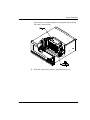
5HSODFLQJWKHFDUWULGJHPDJD]LQH
Open the library door, as described on page 50.
For rack-mount models, remove the front cartridge magazine by
pulling it out first from the right, then the left. For standalone models,
pull it out first from the top, then the bottom.
6FDODU$,7
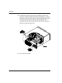
/LEUDU\2SHUDWLRQ
You can access the back magazine by turning the rotor manually.
The rotor is shown below.
If desired, replace the cartridges (described on page 51).
,QVWDOODWLRQDQG2SHUDWLRQ
&KDSWHU
Position the magazine so that the single mounting guide on the
magazine is aligned with the roller on the mounting plate, as shown
in the figure. For rack-mount models, clip the magazine onto the left
side and snap it into place by pressing on the right side. For
standalone models, clip the magazine onto the bottom and snap it
into place by pressing on the top.
Close and lock the door.
6FDODU$,7
/LEUDU\2SHUDWLRQ
6WRULQJFDUWULGJHV
To maximize the shelf life of your tapes and ensure data integrity, follow
these guidelines when storing cartridges:
S Store cartridges in a suitable environment. Follow the
specifications for storage temperature and other environmental
requirements, as described on the cartridge packaging. Do not allow
the temperature and humidity in the storage environment to
fluctuate.
S Keep the storage location as free of airborne particulates as
possible. To eliminate obvious sources of particulates, do not permit
anyone to smoke, eat, or drink near the storage area, and do not store
cartridges near a copier or printer that may emit toner and paper dust.
S Store cartridges with the write-protect switch in the protected
position.
S Store cartridges as soon as possible after you remove them from
the library. Immediate storage helps avoid many of the conditions
that can damage tapes, such as temperature and humidity fluctuation,
particulate contamination, and excessive handling.
S If possible, store cartridges in a cartridge magazine. In the
cartridge magazine, cartridges are protected from airborne
contaminants by a clear plastic cover. With the cover in place, the
magazines can be stacked on top of each other to make the most
efficient use of storage space.
,QVWDOODWLRQDQG2SHUDWLRQ
&KDSWHU
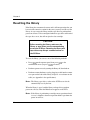
5HVHWWLQJWKHOLEUDU\
If the library has encountered an error and is still not operating after you
have tried the corrective action for the error, you may need to reset the
library. A reset causes the library and the tape drives to perform their
power-on self tests. Unless configured otherwise, tape drives will rewind
the tape after a reset, but will not eject the data cartridge.
&$87,21
%HIRUHUHVHWWLQJWKHOLEUDU\PDNHVXUHWKH
OLEUDU\RUWDSHGULYHVDUHQRWFRPPXQLFDWLQJ
DFURVVWKH6&6,EXV5HVHWWLQJWKHOLEUDU\DQG
WDSHGULYHVPD\GLVUXSWFRPPXQLFDWLRQVRQ
WKH6&6,EXV
To reset the library, you can use one of the following methods:
S Press >5HVHW@ on the operator panel, then press >(QWHU@at the
confirmation screen (or press >(VFDSH@ to cancel).
S Perform a power-on reset by turning the library off, then back on.
S Perform a remote hardware reset by plugging a cable into the remote
reset port on the back of the library and press a reset button on the
cable (see Appendix A for specifications).
1RWH The library, tape drives, or the entire SCSI bus can also be
automatically reset by the host.
When the library is reset, both the library and tape drives perform
power-on self-tests. Then the Main Screen appears on the LCD.
1RWH If the library is performing a cartridge move operation when it
is reset, it completes the move operation before it performs the
power-on self-test.
6FDODU$,7
7DSH'ULYH2SHUDWLRQ
The application software automatically controls the tape drives to
perform backup and restore operations. You do not need to intervene in
the cartridge processing; however, you may need to perform the
following tasks:
S
S
S
S
Monitoring the tape drive LEDs
Cleaning tape drives
Displaying information about tape drives
Ejecting a cartridge manually
1RWH You cannot control tape drives from the operator panel;
however, you can perform diagnostics on tape drives across the
9-pin or 25-pin port. (See page 122 for information about
diagnostics.)
,QVWDOODWLRQDQG2SHUDWLRQ
&KDSWHU
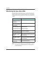
0RQLWRULQJWKHWDSHGULYH/('V
The SDX-300C and SDX-500C tape drive use their three front panel
LEDs to report the current status/operation of the drive. The following
table shows the possible states of the three LEDs and the conditions they
indicate.
/('VWDWH
&RQGLWLRQ
6WDWXVDQG7DSH/('V
IODVKLQJ0RGH%XV\
/('LJQRUHG
(UURU5DWH:DUQLQJFOHDQLQJUHTXHVW
6WDWXV/('IODVKLQJ
6HOIWHVWIDLOXUH
&RGH%XV\DQG7DSH
/('VLJQRUHG
7DSH/('IODVKLQJ&RGH :DLWLQJIRU(MHFW
%XV\/('IODVKLQJ&RGH :DLWLQJIRUUHTXHVW
%XV\/('RII7DSH/(' 7DSHGULYHLVXQORDGHG
RII6WDWXV/('LJQRUHG
%XV\/('RQRUEOLQNLQJ :ULWHHQDEOHGWDSHORDGHGLQGULYHDQG
7DSH/('RQ6WDWXV
WKHWDSHGULYHLVUHDG\WRSHUIRUPWDSH
/('RII
PRWLRQDFWLYLWLHV
%XV\/('RQRUEOLQNLQJ $ZULWHSURWHFWHGWDSHLVORDGHGDQG
7DSH/('RQ6WDWXV
WKHWDSHGULYHLVUHDG\WRSHUIRUPWDSH
/('RQ
PRWLRQDFWLYLWLHV
%RWWRP/('IODVKLQJ
WRS/('RII
7DSHPRWLRQ$IDVWIODVKLQGLFDWHV
KLJKVSHHGWDSHPRWLRQ
1RWH You may see other LED activity (random flashing, steady on,
and so on). For a detailed description, refer to the tape drive
product specification.
6FDODU$,7
7DSH'ULYH2SHUDWLRQ
&OHDQLQJWKHWDSHGULYHV
You should clean a tape drive whenever the library displays “Drive needs
cleaning” on the Main Screen of the LCD or whenever your application
software notifies you. (Not all software applications display cleaning
requirements.) Regular cleaning helps ensure that the tape drives
function reliably.
1RWH Some applications monitor the tape drives’ cleaning needs and
automatically insert the cleaning cartridge in the drive whenever
it needs cleaning. If this is the case, you can skip the cleaning
instructions in this section.
6HOHFWLQJFOHDQLQJFDUWULGJHV
Use a Sony TCL cleaning cartridge to clean any AIT drive.
To order cleaning cartridges, contact ADIC.
&$87,21
8VLQJFORWKVZDEVFRWWRQVZDEVFOHDQLQJ
DJHQWVRUFOHDQLQJFDUWULGJHVQRWDSSURYHG
IRU\RXUWDSHGULYHE\$',&PD\YRLGWKHWDSH
GULYHZDUUDQW\
&OHDQLQJWKHWDSHGULYHIURPWKHRSHUDWRUSDQHO
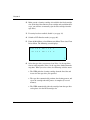
To clean the tape drive from the operator panel:
Determine which tape drive needs cleaning by looking at the drive
LEDs. The Status LED on the drive that requires cleaning will be
flashing Mode 2 (the Tape LED may also be flashing Mode 2).
,QVWDOODWLRQDQG2SHUDWLRQ
&KDSWHU
Make certain a cleaning cartridge is installed in the fixed cartridge
slot. (If the fixed slot contains a data cartridge and you follow these
steps, you will have to manually eject the data cartridge from the
tape drive.)
If security has been enabled, disable it (see page 34).
Switch to LCD Interface mode (see page 46).
From the Main Menu, select Maintenance Menu. Then select Clean
Drives Menu. The following screen displays:
→C l e a n
D r
i v e
1
C l e a n
D r
i v e
2
↓
Select the tape drive you want to clean. Drive 1 is the tape drive
closest to the magazine; Drive 2 is the tape drive farthest from the
magazine. When you select a drive, the following activities occur:
S The CHM picks the cleaning cartridge from the fixed slot and
inserts it in the tape drive you specified.
S The tape drive automatically performs the cleaning process and
ejects the cartridge when the process is complete (in several
minutes).
S The CHM automatically picks the cartridge from the tape drive
and replaces it in the fixed cartridge slot.
6FDODU$,7
7DSH'ULYH2SHUDWLRQ
Confirm that the cleaning was done by looking at the Status LED
on the front of the drive. The Status LED should be off. If the LED
is still on, replace the cleaning cartridge and clean the tape drive
again. If the LED is still on after the second cleaning, there may be
a problem with the tape drive.
³ ,PSRUWDQW
,IWKHWDSHGULYHHMHFWVWKHFOHDQLQJ
FDUWULGJHZLWKLQDPLQXWH\RXQHHGWRUHSODFHWKH
FOHDQLQJFDUWULGJH6HHSDJH IRUFDUWULGJH
UHSODFHPHQWLQVWUXFWLRQV
When the cleaning is complete, return the library to its original
control mode (SCSI Interface mode or one of the sequential modes)
and re-enable security.
'LVSOD\LQJLQIRUPDWLRQDERXWWDSHGULYHV
From the operator panel, you can display information about the tape
drives, including the type of tape drive installed and its operational
status. The information screens are updated whenever there is a change
in drive status.
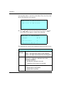
To display tape drive information:
,QVWDOODWLRQDQG2SHUDWLRQ
&KDSWHU
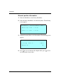
From the Main Menu, select Library Info Menu. Then select Drive Info
Menu. The following screen appears:
→D r i v e
D r
i v e
1
S t a t u s
2
S t a t u s
↓
Press >@ or >@to select the desired tape drive and press >(QWHU@. A
Drive Status screen appears, similar to the following:
D R I V E
1
S T A T U S :
T y p e
A I T
P r e s e n t
1
A c c e s s i b l e
1
↓
The following table describes the information in the Drive Status screen.
'ULYH6WDWXVVFUHHQ
'ULYH1
67$786
,GHQWLILHVWKHWDSHGULYHDVIROORZV
'ULYH²7KHWDSHGULYHFORVHVWWRWKHPDJD]LQH
'ULYH²7KHWDSHGULYHIDUWKHVWIURPWKHPDJD]LQH
7\SH
,GHQWLILHVWKHWDSHGULYHPRGHO
1RWH,IPPDSSHDUVLWLQGLFDWHVRQHRIWKH
IROORZLQJFRQGLWLRQV
S No tape drive is present in that slot.
S A tape drive firmware error has occurred.
3UHVHQW
,QGLFDWHVZKHWKHUDWDSHGULYHLVLQVWDOOHG
²$WDSHGULYHLVQRWSUHVHQW
²$WDSHGULYHLVSUHVHQW
6FDODU$,7
7DSH'ULYH2SHUDWLRQ
'ULYH6WDWXVVFUHHQ
$FFHVVLEOH
,QGLFDWHVWKHDFFHVVLELOLW\RIWKHWDSHGULYHWRWKH
&+0
² $FDUWULGJHLVORDGHGLQWKHWDSHGULYHRUWKHWDSH
GULYH
VVWDWXVLVXQNQRZQ
² $FDUWULGJHLVSURWUXGLQJIURPWKHWDSHGULYHRU
WKH
GULYHLVHPSW\
&OHDQ
² 7KHWDSHGULYHLVFOHDQ
² 7KHWDSHGULYHQHHGVWREHFOHDQHGRUWKHFOHDQLQJ
WDSHLVXVHGXS
:DUQLQJ
1RWFXUUHQWO\XVHG
2FFXSLHG
² 7KHUHLVQRFDUWULGJHORDGHGLQWKHWDSHGULYH
² 7KHUHLVFXUUHQWO\DFDUWULGJHORDGHGLQWKHWDSH
GULYH
2FF9DOLG ² 7KHGRRUKDVEHHQRSHQHGRUVRPHRWKHU
2FFXSLHG
LQWHUUXSWLRQKDVRFFXUUHGVRWKHRFFXSLHG
9DOLG
LQIRUPDWLRQPD\QRWEHUHOLDEOH
² 7KHRFFXSLHGLQIRUPDWLRQLVUHOLDEOH
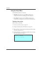
(MHFWLQJDFDUWULGJHPDQXDOO\
If a problem occurs that requires intervention, you may need to manually
eject a cartridge.
To eject a cartridge:
Open the library door (see page 50).
Press the eject button on the tape drive's faceplate.
The following figure shows the location of the eject button on the AIT
drive.
,QVWDOODWLRQDQG2SHUDWLRQ
&KDSWHU
BUSY TAPE STATUS
EJECT
BUTTON
6FDODU$,7
0DLQWHQDQFH
This chapter describes the following:
S
S
S
S
Cleaning requirements for the library
Replacing the fuse
Replacing the air filter
Replacing the tape drives
&$87,21
8QOHVV\RXKDYHDVHOIPDLQWHQDQFHFRQWUDFW
ZLWK$',&GRQRWDWWHPSWWRUHSODFHDQ\
FRPSRQHQWVLQWKHOLEUDU\RWKHUWKDQWKHWDSH
GULYHVIXVHDQGDLUILOWHU,I\RXGRVR\RXZLOO
YRLG\RXUZDUUDQW\
,QVWDOODWLRQDQG2SHUDWLRQ
&KDSWHU
&OHDQLQJUHTXLUHPHQWV
The only library components that should be cleaned are the tape drives
and the window in the door. Instructions for cleaning the tape drives are
provided on page 59.
&$87,21
7KHOLEUDU\
VLQWHUQDOFRPSRQHQWVDUHOXEULFDWHG
DWWKHIDFWRU\DQGVKRXOGQRWEHFOHDQHGRU
UHOXEULFDWHG
To protect the internal components from dust, keep the library door
closed and locked.
&OHDQLQJWKHOLEUDU\ZLQGRZ
To clean the library's window, use the cleaning packet provided with the
library. (To order additional cleaning packets, see page xv)
&$87,21
7RDYRLGVFUDWFKLQJWKHZLQGRZGRQRWXVH
DEUDVLYHFOHDQHUVDEUDVLYHFOHDQLQJLPSOHPHQWV
KDUVKFKHPLFDOVRUVROYHQWV
6FDODU$,7
0DLQWHQDQFH
5HSODFLQJWKHIXVH
The library uses a 2.5 amp, 250-volt fuse, which is located in the fuse
drawer at the back of the library next to the power cord connector. An
extra fuse is provided in the fuse drawer. To order additional fuses, see
page xv.
&$87,21
:KHQUHSODFLQJWKHOLEUDU\
VIXVHXVHRQO\WKH
VDPHW\SHDQGUDWLQJRIIXVH
To replace the library's fuse:
Turn off the library and remove the power cord.
.
:$51,1*
%HIRUHSHUIRUPLQJDQ\RIWKHIROORZLQJVWHSVEH
VXUHWKDWWKHSRZHUVZLWFKLVRIIDQGWKHSRZHU
FRUGLVGLVFRQQHFWHGIURPWKHOLEUDU\
Place a small screwdriver underneath the tab on the fuse drawer.
Gently lift out the fuse drawer.
,QVWDOODWLRQDQG2SHUDWLRQ
&KDSWHU
Pull the blown fuse out of the fuse slot.
Use the screwdriver to push the spare fuse box out of the fuse drawer.
Remove the spare fuse and place it in the fuse slot.
Insert the fuse drawer into the back panel. Push in until you hear it
snap into place.
If desired, order another spare fuse for the fuse drawer.
6FDODU$,7
0DLQWHQDQFH
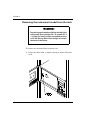
5HSODFLQJWKHDLUILOWHU
The library includes an air filter, located behind the door. The air filter
should be replaced once a year (or more frequently if the library is
operating in a dirty environment). To order replacement filters, see
page xv.
³ ,PSRUWDQW
$LUILOWHUVSURWHFWWKHOLEUDU\IURP
ODUJHFRQWDPLQDQWVEXWDUHQRWLQWHQGHGWRNHHS
WKHWDSHGULYHVFOHDQ<RXPXVWVWLOOFOHDQWKHWDSH
GULYHVRQDUHJXODUEDVLVDVGHVFULEHGRQSDJH To replace the air filter:
Unlock and open the library's door (see page 50).
From inside the door, use a T-15 TORX bit to remove the three
screws that secure the metal filter cover to the front door, as shown
in the figures on the next page.
Remove the metal filter cover and pull out the filter.
1RWH The rack-mount model contains one long filter; the standalone
contains two smaller filters.
Replace the new filter inside the door.
,QVWDOODWLRQDQG2SHUDWLRQ
&KDSWHU
Position the metal cover over the filter. Using a T-15 TORX bit,
replace the three screws that secure the metal cover inside the front
panel.
5DFNPRXQWPRGHO
6WDQGDORQHPRGHO
6FDODU$,7
0DLQWHQDQFH
5HSODFLQJDWDSHGULYHRUGULYHEODQN
³ ,PSRUWDQW
'RQRWPL[GLIIHUHQW6&6,
FRQILJXUDWLRQVZLWKLQWKHVDPHOLEUDU\
Replacing a tape drive (or drive blank) involves the following steps:
6WHS
'HVFULSWLRQ
3UHSDUHIRUWKHUHSODFHPHQWSURFHGXUH
5HPRYHWKHWDSHGULYH
,QVWDOOWKHWDSHGULYH
5HVXPHOLEUDU\RSHUDWLRQV
1RWH When you order a new tape drive for the library, the tape drive
will be shipped to you in the drive carrier. You cannot install a tape
drive into the library without a drive carrier.
,QVWDOODWLRQDQG2SHUDWLRQ
&KDSWHU
6WHS²3UHSDUHIRUUHSODFHPHQW
Obtain a flat blade screwdriver. (Some models may require a #1
Phillips screwdriver.)
Ensure that the environment is free of conditions that could cause
electrostatic discharge (ESD). If possible, use an antistatic mat and
grounded static protection wristband during installation. If a mat and
wristband are not available, touch a known grounded surface, such
as the computer's metal chassis.
Unlock and open the library's door (see page 50).
Turn the library's power switch to off.
Disconnect the power cord.
:$51,1*
%HIRUHSHUIRUPLQJDQ\RIWKHIROORZLQJVWHSVEH
VXUHWKDWWKHSRZHUVZLWFKLVRIIDQGWKHSRZHU
FRUGLVGLVFRQQHFWHGIURPWKHOLEUDU\
If necessary, reach in and push firmly against the base of the CHM
to move it so it is not blocking access to the tape drives.
6FDODU$,7
0DLQWHQDQFH
6WHS²5HPRYHWKHWDSHGULYH
To remove the tape drive:
Using a flat blade screwdriver, loosen the two captive screws on
each side of the faceplate. (Some models may require a #1 Phillips
screwdriver.)
,QVWDOODWLRQDQG2SHUDWLRQ
&KDSWHU
Using your finger, pull out the lever on the faceplate. The figures on
page 75 show the location of the lever.
&$87,21
'RQRWSXOORXWWKHOHYHUZLWKRXWILUVWORRVHQLQJ
WKHVFUHZV
Pull the tape drive out of its slot.
6WHS²,QVWDOOWKHWDSHGULYH
³ ,PSRUWDQW
:KLOHLQVWDOOLQJDWDSHGULYHPDNH
VXUH\RXGRQRWVWLFN\RXUILQJHUVLQWKHGULYH
GRRU
Insert the tape drive as shown on the next page. Make sure the
lever is closed. The drive should slide easily toward the back.
6FDODU$,7
0DLQWHQDQFH
5DFNPRXQW
PRGHO
,QVHUWWKH
WDSHGULYH
ZLWKWKHOHYHU
WRZDUGWKH
ERWWRP
6WDQGDORQH
PRGHO
,QVHUWWKH
WDSHGULYH
ZLWKWKHOHYHU
WRZDUGWKH
ULJKW
,QVWDOODWLRQDQG2SHUDWLRQ
&KDSWHU
When the tape drive is almost completely inside the slot, you will
feel some resistance. This is caused by the connection between the
tape drive and the library's controller card. To seat the connection,
push firmly against the drive until you can push no further.
Tighten the captive screws on each end of the drive carrier faceplate.
6WHS²5HVXPHRSHUDWLRQV
Reconnect the power cord.
&$87,21
7RDYRLGGDPDJLQJWKHWDSHGULYHPDNHVXUH
WKHOLEUDU\LVSRZHUHGRIIZKHQ\RXFRQQHFWLW
WRWKH6&6,EXV
Close and lock the library's door.
Turn on the library. The library will take approximately one minute
to complete its power-on self-test.
1RWH When you replace a tape drive, the new drive automatically
assumes the SCSI ID of the old tape drive. If you want to view
or change the SCSI ID of the new tape drive, see page 30.
6FDODU$,7
6KLSSLQJWKH/LEUDU\
This chapter describes procedures for:
S Returning the library for service
S Packing the library
5HWXUQLQJWKHOLEUDU\IRUVHUYLFH
Most service procedures for your ADIC library will be performed
on-site. In the event that you need to return the library to the factory for
service, contact your service provider. If your service provider instructs
you to return the library directly to ADIC, contact ADIC Technical
Support to obtain a Return Materials Authorization (RMA) number and
the shipping address (see page xv). When you have the RMA number,
follow the packing instructions on the following pages.
,QVWDOODWLRQDQG2SHUDWLRQ
&KDSWHU
3DFNLQJWKHOLEUDU\
Use the original packing materials to pack the library (shipping
containers, foam packing pieces, and antistatic bag). You will also need
packing tape and banding material.
&$87,21
7RDYRLGGDPDJLQJWKHOLEUDU\DQGYRLGLQJ\RXU
ZDUUDQW\EHVXUHWRXVHWKHRULJLQDOVKLSSLQJ
PDWHULDOVRUUHSODFHPHQWPDWHULDOVREWDLQHG
IURP\RXUYHQGRUZKHQUHSDFNLQJDQGVKLSSLQJ
WKHOLEUDU\'RQRWXVHWKHVKLSSLQJFDUWRQDQG
SDFNLQJPDWHULDOVWRVKLSLWHPVRWKHUWKDQD
OLEUDU\
3UHSDULQJWKHOLEUDU\IRUVKLSSLQJ
To prepare the library for shipping:
Remove all cartridges from the magazines. Make certain the CHM
gripper and the tape drives do not contain cartridges. Do not remove
the magazines.
Power off the library.
Remove the keys, power cord, the SCSI cables and any terminators
or jumpers. Do not ship these items if you are returning the library
to the factory.
6FDODU$,7
6KLSSLQJWKH/LEUDU\
Insert the small foam packing piece in the cartridge magazine, as
shown in the figures.
5DFNPRXQWPRGHO
3ODFHWKHIRDPRQWKHOHIW
VLGHRIWKHPDJD]LQH
6WDQGDORQHPRGHO
3ODFHWKHIRDPRQWKHWRS
KDOIRIWKHPDJD]LQH
,QVWDOODWLRQDQG2SHUDWLRQ
&KDSWHU
Move the CHM so that it is centered in front of the foam packing
piece. Push the upper portion of the CHM forward until it is secure
between the sides of the foam.
5DFNPRXQWPRGHO
6WDQGDORQHPRGHO
6FDODU$,7
6KLSSLQJWKH/LEUDU\
Insert the large foam packing piece between the CHM and the door
opening, as shown below. Make certain the foam is flush against the
upper base of the CHM.
5DFNPRXQWPRGHO
6WDQGDORQHPRGHO
Close and lock the library door. Remove the key.
,QVWDOODWLRQDQG2SHUDWLRQ
&KDSWHU
5HPRYLQJWKHUDFNPRXQWPRGHOIURPWKHUDFN
:$51,1*
'HSHQGLQJRQWKHQXPEHURIGULYHVLQVWDOOHGWKH
UDFNPRXQWOLEUDU\ZHLJKV²SRXQGV
²NJ$WOHDVWSHRSOHDUHQHHGHGWRPRYH
RUOLIWWKHOLEUDU\0RVWRIWKHZHLJKWLVWRZDUG
WKHEDFNRIWKHOLEUDU\
To remove the rack-mount library from the rack:
Locate the cabinet latch, as shown in the figure below. Pull on the
latch.
.
6FDODU$,7
6KLSSLQJWKH/LEUDU\
Slide the library forward until the rails stop at their spring clips.
Using two people, press the spring clips to disengage the rails and
lift the library out of the rack.
.
If you are shipping the slide rails with the library, use a T-20 TORX
driver to remove the four screws that attach each rack slide rail to
the front and rear of the cabinet. (See the figure on page 5.)
1RWH If clips nuts are attached to the rack, remove them.
Attach the two rack slide rails to the sides of the library.
,QVWDOODWLRQDQG2SHUDWLRQ
&KDSWHU
3DFNLQJWKHOLEUDU\
:$51,1*
7KHUDFNPRXQWOLEUDU\ZHLJKV²SRXQGV
²NJWKHVWDQGDORQHOLEUDU\ZHLJKV
²SRXQGV ² NJ$WOHDVWSHRSOH
DUHQHHGHGWRPRYHRUOLIWWKHOLEUDU\0RVWRIWKH
ZHLJKWLVWRZDUGWKHEDFNRIWKHOLEUDU\
1RWH The packaging for your library may differ from the packaging
described in these instructions. For the most current packing
instructions, contact ADIC Technical Support.
Refer to the figure on the next page and pack the library as follows:
Place the library on top of the bottom cushion, then place the
antistatic bag over the library, as shown in the figure on the next
page. For the standalone model, place the library on its side (CHM
base down).
6FDODU$,7
6KLSSLQJWKH/LEUDU\
,QVWDOODWLRQDQG2SHUDWLRQ
&KDSWHU
Place the cushioned packaging around the library, as shown below.
(Use the alignment holes in the packing pieces as a guide.)
Place the cushioned top over the library. (Use the alignment holes
in the packing pieces as a guide.)
If you are shipping accessories with the library, place the accessory
box between the two top packing cushions.
Lay the necessary paperwork in the top of the library box.
6FDODU$,7
6KLSSLQJWKH/LEUDU\
Place the carton over the library, as shown in the figure, and tape the
box shut.
,QVWDOODWLRQDQG2SHUDWLRQ
&KDSWHU
Place the shipping label on the box.
Place the library on the wooden pallet. Secure banding material
around the box and through the wooden pallet.
6FDODU$,7
$GYDQFHG2SHUDWLRQ
This chapter describes advanced operations you can perform from the
operator panel:
S Viewing library information, which includes SCSI data, hardware
operating statistics and status, command history, and cartridge
inventory
S Performing diagnostics on the library
S Configuring ports for diagnostics
Many of the tasks described in this chapter may be necessary if you want
to troubleshoot library hardware operations.
8VLQJHOHPHQWV
Elements are the physical locations in the library that can accept a
cartridge (the CHM, the magazine slots, the fixed slot, and the two tape
drives).
,QVWDOODWLRQDQG2SHUDWLRQ
&KDSWHU
(OHPHQWLQGH[HV
Each element has an element index, which enables the library to identify
the elements. Many LCD functions require you to use element indexes.
For example, to move a cartridge using the Diagnostics Menu, you must
specify the source and destination element indexes. The source is either
a cartridge slot or the tape drive where the CHM will pick a cartridge.
The destination is either the slot or the tape drive where the CHM will
place the cartridge.
The following diagrams show the element indexes assigned for the
library.
,QGH[HVIRUWKHUDFNPRXQWPRGHO
6FDODU$,7
$GYDQFHG2SHUDWLRQ
,QGH[HVIRUWKHVWDQGDORQHPRGHO
(OHPHQWDGGUHVVHV
Your application software may use element addresses to identify
elements in the library. The difference between an element index and an
element address is that an index is a fixed number set by the library,
whereas an address can be changed by your application software (using
the SCSI command, MODE SELECT).
The element indexes correspond to the library's default element
addresses. To verify the current element addresses, display the SCSI
Mode Parameters screen (see page 93).
,QVWDOODWLRQDQG2SHUDWLRQ
&KDSWHU
9LHZLQJOLEUDU\LQIRUPDWLRQ
The functions in the Library Information Menu are mainly for use by
technical support and application developers. If you are an end-user, you
may be asked by technical support to display one of these screens and
locate information that will help troubleshoot a problem.
This section describes the following library information:
S SCSI Menu. Contains SCSI mode parameters, reservations, and
sense data.
S Statistics. Contains data about CHM operations and elements.
S System sensors. Contains information about the library's
mechanical sensors.
S Command history. Displays the contents of the history buffer.
S Inventory Menu. Contains information about bar code labels and
elements.
6FDODU$,7
$GYDQFHG2SHUDWLRQ
9LHZLQJ6&6,GDWD
SCSI information is available through the SCSI Menu. To display this
menu, select Library Info Menu from the Main Menu, then select SCSI
Menu. The following menu appears:
→S C S I
M o d e
P a r a m s
S C S I
R e s e r v a t
S C S I
S e n s e
i o n s
D a t a
↓
6&6,0RGHSDUDPHWHUV
The SCSI Mode Parameters screen displays the settings of various
operating mode parameters. These parameters are equivalent to the
parameters reported by the library in response to a MODE SENSE
command, issued by the application software. Typically, the values of
these parameters are changed by a MODE SELECT command.
To view these parameters, select SCSI Mode Params from the SCSI
Menu. The following screen appears:
E L E M E N T
A D D R
C H M
A d d r
,
C u r
8 6
C H M
A d d r
,
D e f
8 6
C H M
A d d r
,
S a v
8 6 ↓
,QVWDOODWLRQDQG2SHUDWLRQ
P A G E :
&KDSWHU
For each parameter, the SCSI Mode Parameters screen shows the current
(Cur), default (Def), and saved (Sav) values:
S The current value is the value currently active. It is either the
power-on default or a temporary value set by the latest MODE
SELECT command.
S The default value is the original value set at the factory.
S The saved value is the value specified as the power-on default by a
MODE SELECT command. After a saved value has been specified
with a MODE SELECT command, this value takes effect
immediately and each time you power on the library.
The table below describes the items on the SCSI Mode Parameters
screen:
6&6,0RGHSDUDPHWHUV
&+0
$GGU
7KHHOHPHQWDGGUHVVRIWKHFDUWULGJHKDQGOLQJ
PHFKDQLVP&+0
6WRU$GGU
7KHHOHPHQWDGGUHVVRIWKHILUVWVWRUDJHORFDWLRQ
ZKLFKLVWKHIL[HGFDUWULGJHVORW6HHSDJHVDQG
IRUDFRPSOHWHQXPEHULQJVFKHPH
'ULYH
$GGU
7KHHOHPHQWDGGUHVVRIWKHILUVWWDSHGULYHFORVHVW
WRWKHPDJD]LQH7KHRWKHUWDSHGULYHLVQXPEHUHG
FRQVHFXWLYHO\
'ULYH1XP
7KHQXPEHURIWDSHGULYHVLQVWDOOHG
3DULW\
:KHWKHU6&6,SDULW\FKHFNLQJLVHQDEOHGIRUWKH
OLEUDU\:KHQWKHSDULW\RSWLRQLVRQWKHOLEUDU\
FKHFNVDOOGDWDFRPLQJDFURVVWKH6&6,EXVIRUSDULW\
3W\5HWU\
7KHQXPEHURIWLPHVWKHOLEUDU\ZLOOUHWU\D6&6,
SKDVHDIWHUGHWHFWLQJDSDULW\HUURU
6FDODU$,7
$GYDQFHG2SHUDWLRQ
6&6,0RGHSDUDPHWHUV
6HFXULW\
:KHWKHUVHFXULW\KDVEHHQHQDEOHGE\6&6,RUQRW
6HFXULW\DOVRFDQEHHQDEOHGIURPWKH/&'VHH
SDJH IRUPRUHLQIRUPDWLRQ
:U/LQH
WKURXJK
:U/LQH
:KHWKHUWKHWH[WGLVSOD\HGRQHDFKRIWKHIRXUOLQHV
RQWKH0DLQ6FUHHQLVGHILQHGE\WKH/&'0RGHSDJH
LQ6&6,
:KHQVHWWRWKHLUGHIDXOWYDOXHVWKHHOHPHQWDGGUHVVHVUHSRUWHGRQWKLVVFUHHQDUH
WKHVDPHDVHOHPHQWLQGH[HVVKRZQRQSDJHVDQG+RZHYHUXQOLNHHOHPHQW
LQGH[HVZKLFKFDQQRWEHFKDQJHGDGGUHVVHVFDQEHFKDQJHGZLWKD02'(
6(/(&7FRPPDQG
6&6,UHVHUYDWLRQV
The SCSI Reservations screen indicates if the library or its elements are
reserved for exclusive use by a host computer. The library and its
elements are reserved and released through SCSI commands
(RESERVE and RELEASE).
You may want to view SCSI reservations if you are operating the library
in a multi-host environment and you want to determine which elements
are reserved by which host. Multiple hosts can reserve different elements
within a single library. For example, Host 1 could reserve the first
magazine, while Host 2 could reserve the second magazine.
,QVWDOODWLRQDQG2SHUDWLRQ
&KDSWHU
%o view SCSI reservations:
Select SCSI Reservations from the SCSI Menu. The first screen to
appear is the Unit Reservation screen:
U N I T
R E S E R V A T I O N :
U n i
R e s e r v e d :
0
I D :
0
t
H o s t
↓
To display the Element Reservations screen, press >@to scroll past
the last item in the Unit Reservation screen.
E L E M
↑
R E S E R V A T I O N S :
E l e m
E l e m
H o s t
R e s
A d d r
T y p e
I D
0
S L O T
- N O N E -
I D
↓
To view other elements, press >@ and >@. To return to the SCSI
Menu, press >(VFDSH@.
6FDODU$,7
$GYDQFHG2SHUDWLRQ
The information in the SCSI Reservations screen is described in the
following table.
8QLWUHVHUYDWLRQV
8QLW
5HVHUYDWLRQ
7KHOLEUDU\
VUHVHUYDWLRQVWDWXVLILWLVUHVHUYHG
RULILWLVQRWDQGWKHKRVW
V,'LIWKHOLEUDU\LV
UHVHUYHG
(OHPUHVHUYDWLRQV
(OHP$GGU
7KHDGGUHVVRIWKHHOHPHQW
(OHP7\SH
7KHFDWHJRU\RIHOHPHQWV7KHUHDUHWKUHH
FDWHJRULHV&+0'ULYHDQG6ORW
+RVW,'
7KH6&6,,'RIWKHKRVWWKDWFXUUHQWO\KDVWKH
HOHPHQWUHVHUYHG
5HV,'
7KH,'WKDWWKHHOHPHQWLVUHVHUYHGXQGHU7KLV
LVDQXPEHUDVVLJQHGWRWKHHOHPHQWE\DKRVW
ZKHQWKHUHVHUYDWLRQZDVPDGH,IWKHUHLVQR
UHVHUYDWLRQWKH5HV,'DQG+RVW,'FROXPQV
GLVSOD\´121(µ
6&6,VHQVHGDWD
When an error or change of state occurs, the application software can
issue a SCSI REQUEST SENSE command to the library to obtain
information. Some of this information, called sense data, is displayed
on the SCSI Sense Data screen. Sense data provides information to help
you diagnose problems with the library.
,QVWDOODWLRQDQG2SHUDWLRQ
&KDSWHU
To view the sense data:
Select SCSI Sense Data from the SCSI Menu. The following screen
appears:
S e n s e
D a t a ,
I D
0
K E Y
0 h
B y t e 1 5
0 0 h
A S C
0 0 h
B y t e 1 6
0 0 h
A S C Q
0 0 h
B y t e 1 7
0 0 h
The ID at the top of the display is the SCSI ID of the host that the
sense data is being held for. (Note that sense data is supplied for
inactive IDs as well as active IDs.)
To view other devices, press >@ and >@. To return to the SCSI Menu,
press >(VFDSH@.
6FDODU$,7
$GYDQFHG2SHUDWLRQ
The following table describes the information in the Sense Data screen.
6HQVHGDWD
.(<
7KLVLVWKHVHQVHNH\UHWXUQHGE\WKH5(48(676(16(FRPPDQG7KH
VHQVHNH\VDUH
K²1R6HQVH7KHUHLVQRVSHFLILFVHQVHNH\LQIRUPDWLRQWRUHSRUW
K²1RW5HDG\7KHOLEUDU\LVQRWUHDG\WRSHUIRUPPRWLRQFRPPDQGV
K²+DUGZDUH(UURU7KHOLEUDU\GHWHFWHGDKDUGZDUHIDLOXUHGXULQJD
VHOIWHVWRUZKLOHSHUIRUPLQJDFRPPDQG2SHUDWRULQWHUYHQWLRQPD\EH
UHTXLUHG
K²,OOHJDO5HTXHVW7KHUHZDVDQLOOHJDOSDUDPHWHULQWKHFRPPDQG
GHVFULSWRUEORFNRULQWKHDGGLWLRQDOSDUDPHWHUVVXSSOLHGDVGDWDIRUD
FRPPDQGRUWKHOLEUDU\LVLQWKHZURQJPRGHWRH[HFXWHWKHFRPPDQG
K²8QLW$WWHQWLRQ7KHFDUWULGJHLQYHQWRU\PD\KDYHEHHQYLRODWHG
%K²$ERUWHG&RPPDQG7KHOLEUDU\DERUWHGWKHFRPPDQG7KHLQLWLDWRU
PD\EHDEOHWRUHFRYHUE\WU\LQJWKHFRPPDQGDJDLQ
$6&
7KLVLVWKH$GGLWLRQDO6HQVH&RGHZKLFKDORQJZLWKWKH$GGLWLRQDO
6HQVH&RGH4XDOLILHUSURYLGHVLQIRUPDWLRQGHVFULELQJDVSHFLILFHUURU
FRQGLWLRQ
$6&4
7KLVLVWKH$GGLWLRQDO6HQVH&RGH4XDOLILHUZKLFKDORQJZLWKWKH
$GGLWLRQDO6HQVH&RGHSURYLGHVLQIRUPDWLRQGHVFULELQJDVSHFLILFHUURU
FRQGLWLRQ
%\WH
7KLVLVWKH6HQVH.H\6SHFLILFGDWDZKLFKSURYLGHVDGGLWLRQDO
LQIRUPDWLRQDERXWDQHUURUFRQGLWLRQ7KLVLQIRUPDWLRQLVYDOLGRQO\IRU
WKH,OOHJDO5HTXHVWKVHQVHNH\
%\WH
7KLVLVWKHILUVWE\WHRIWKH)LHOG3RLQWHUGDWD,WLQGLFDWHVZKLFKE\WHLQ
WKHFRPPDQGKDGDQHUURU7KLVLQIRUPDWLRQLVYDOLGRQO\IRUWKH,OOHJDO
5HTXHVWKVHQVHNH\
%\WH
7KLVLVWKHVHFRQGE\WHRIWKH)LHOG3RLQWHUGDWD7KLVLQIRUPDWLRQLVYDOLG
RQO\IRUWKH,OOHJDO5HTXHVWKVHQVHNH\
,QVWDOODWLRQDQG2SHUDWLRQ
&KDSWHU
9LHZLQJVWDWLVWLFV
The Statistics Menu contains two selections: one for reviewing
information about CHM movements and one for reviewing information
about elements. To view statistics:
Select Library Info Menu from the Main Menu, then select Statistics.
The first screen to appear is the System Stat Totals screen:
S Y S T E M
S T A T
T O T A L S :
M o v e s
P i c k
P u t
7 1 0 7
R e t
R e t
r y
0
0 ↓
r y
To display the Element Stats screen, press >@ to scroll past the last
item in the System Stat screen.
E L E M
S T A T S ,
T o t a l
R e t
r
P u t
I N X =
P u t s :
i e s :
P i c k
0
S c a n
0 : ↑
0
0
0 ↓
6FDODU$,7
$GYDQFHG2SHUDWLRQ
The following table describes the information in the Statistics screen.
6\VWHPVWDWLVWLFV
0RYHV
7KHQXPEHURIWLPHVWKH&+0KDVSLFNHGD
FDUWULGJHDQGSODFHGLWLQDVORWRUWDSHGULYH
3LFN5HWU\
7KHQXPEHURIWLPHVWKH&+0UHWULHGSLFNLQJD
FDUWULGJH
3XW5HWU\
7KHQXPEHURIWLPHVWKH&+0UHWULHGSODFLQJD
FDUWULGJH
''EO3LNV
7KHQXPEHURIWLPHVWKHOLEUDU\KDGWRJUDED
FDUWULGJHWZLFHWRUHPRYHLWIURPWKHWDSHGULYHLQ
'ULYHVORWRU$'EO3LNUHVXOWVZKHQWKH
FDUWULGJHLVQRWHMHFWHGIDUHQRXJKIRUWKH&+0WR
JUDVS
''EO3LNV
6FDQV
7KHQXPEHURIWLPHVWKHOLEUDU\VFDQQHGDEDUFRGH
ODEHO
6FDQ5HWU\
7KHQXPEHURIWLPHVWKHOLEUDU\UHWULHGVFDQQLQJD
EDUFRGHODEHO
6FDQ)DLO
7KHQXPEHURIWLPHVWKHOLEUDU\IDLOHGWRVFDQDEDU
FRGH7KHOLEUDU\WULHGWRVFDQDEDUFRGHVHYHUDO
WLPHVEHIRUHLWORJVDIDLOXUH
(OHPHQWVWDWLVWLFV
7RWDO3XWV
7KHQXPEHURIWLPHVDFDUWULGJHZDVSODFHGLQWKDW
HOHPHQWVLQFHWKHOLEUDU\ZDVWXUQHGRQ
5HWULHV3LFN
7KHQXPEHURIWLPHVWKHOLEUDU\UHWULHGSLFNLQJ
IURPWKDWHOHPHQW
5HWULHV3XW
7KHQXPEHURIWLPHVWKHOLEUDU\UHWULHGSODFLQJD
FDUWULGJHLQWKDWHOHPHQW
5HWULHV6FDQ 7KHQXPEHURIWLPHVWKHOLEUDU\UHWULHGVFDQQLQJ
WKDWHOHPHQW
,I\RXUOLEUDU\GRHVQRWLQFOXGHDEDUFRGHVFDQQHUWKHVHILHOGVDOZD\VGLVSOD\
]HUR
,QVWDOODWLRQDQG2SHUDWLRQ
&KDSWHU
9LHZLQJV\VWHPVHQVRUV
The System Sensors screens enable you to troubleshoot hardware
problems by checking the current status of the library's internal
mechanical sensors. To view system sensors:
Select Library Infer Menu from the Main Menu, then select System
Sensors. The Digital Sensors screen is the first to appear:
D I G I T A L
D o o r
K e y
G r
S E N S O R S :
C l o s e d
1
L o c k
i p p e r
1
0 ↓
H o m e
To display the Analog Sensor screen, press >@to scroll past the last
item on the Digital Sensors screen.
A N A L O G
T e m p e r a t u r e :
↑
S E N S O R S :
2 3
+ 1 2 V :
1 1 8 1 6
- 1 2 V :
- 1 2 2 3 3
C
m V
m V ↓
6FDODU$,7
$GYDQFHG2SHUDWLRQ
The following table describes the information in the System Sensors
screens.
'LJLWDOV\VWHPVHQVRUV
'RRU
&ORVHG
,QGLFDWHVZKHWKHUWKHIURQWGRRULVFORVHGRURSHQ
.H\ORFN
,QGLFDWHVZKHWKHUWKHIURQWGRRULVORFNHGRU
XQORFNHG
*ULSSHU
+RPH
,QGLFDWHVZKHWKHUWKHJULSSHULVORFDWHGLQLWVKRPH
SRVLWLRQRUQRW7KHJULSSHULVLQLWVKRPH
SRVLWLRQZKHQWKHJULSSHUILQJHUVDUHRSHQ
&DUW
6HDWHG
,QGLFDWHVZKHWKHUWKHFDUWULGJHLVVHDWHGLQWKH&+0
RUQRW
$QDORJV\VWHPVHQVRUV
7HP
SHUDWXUH
,QGLFDWHVWKHWHPSHUDWXUHRIWKHOLEUDU\LQGHJUHHV
&HOVLXV
9
,QGLFDWHVWKHRXWSXWRIWKHYROWSRZHUVXSSO\LQ
PLOOLYROWV
9
,QGLFDWHVWKHRXWSXWRIWKH²YROWSRZHUVXSSO\LQ
PLOOLYROWV
9
,QGLFDWHVWKHRXWSXWRIWKHYROWSRZHUVXSSO\LQ
PLOOLYROWV
9LHZLQJWKHFRPPDQGKLVWRU\
The Command History screen creates a display of the most recent 300
events that have occurred in the library. If you contact technical support
personnel, a technician may ask you to scroll through this buffer looking
for particular events.
,QVWDOODWLRQDQG2SHUDWLRQ
&KDSWHU
To display the command history:
From the Main Menu, select Library Info Menu.
From the Library Info Menu, select Command History. The system
displays a screen similar to the following:
0 0 0
M O V E
M o v e
f
1 9 : 3 7 : 4 5
r o m
8
t o
8 2
c o m p l e t e
1 8 6 1
1 2 - 2 7 - 9 5
0 4 4 4 1
Scroll through the buffer by pressing >@ and >@.
To exit the command history screen, press >(VFDSH@.
The following table briefly describes the Command History screen. For
complete details, refer to the History Buffer Display in the maintenance
manual for your library.
6KRZQLQ
VDPSOH
)LHOGQDPH
'HVFULSWLRQ
,';,QGH[ 7KHOLQHQXPEHURIWKLVHYHQWZLWKLQWKH
&RPPDQG+LVWRU\7KHUDQJHLVWKH
PRVWUHFHQWHYHQWWKURXJK7KH
PRVWUHFHQWHYHQWLVGLVSOD\HGILUVW
029(
)URP
7KHSURFHVVWKDWORJJHGWKLVHYHQW
7LPH
7KHWLPHDFFRUGLQJWRWKHOLEUDU\
V
LQWHUQDOFORFNWKDWWKHHYHQWWRRNSODFH
0RYHIURP 'HVFULSWLRQ 'HVFULSWLRQRIWKHHYHQW
WR
FRPSOHWH
6FDODU$,7
$GYDQFHG2SHUDWLRQ
6KRZQLQ
VDPSOH
)LHOGQDPH
'HVFULSWLRQ
/LQH
7KHOLQHQXPEHURIWKHVRXUFHFRGHWKDW
ORJJHGWKLVHYHQW
'DWH
7KHGDWHDFFRUGLQJWRWKHOLEUDU\
V
LQWHUQDOFDOHQGDUWKDWWKHHYHQWWRRN
SODFH
6HT
7KHVHTXHQFHQXPEHURIWKLVHYHQW
DFURVVDOOV\VWHPEXIIHUV
9LHZLQJLQYHQWRU\LQIRUPDWLRQ
The library stores inventory information in nonvolatile RAM and uses
the information to process SCSI commands from the application
software. The inventory contains information about the following
element locations:
S CHM
S Cartridge slots
S Tape drives
The Inventory Menu allows you to display the following information:
S Bar Code Label information. This includes data about whether the
bar code scanner could accurately scan the label.
S Element occupied information. This includes data about whether
the element contains a cartridge and whether a magazine or tape
drive is installed.
S Element position information. This includes data about the exact
position of each element.
,QVWDOODWLRQDQG2SHUDWLRQ
&KDSWHU
%DUFRGHODEHOLQIRUPDWLRQ
If your library is equipped with a bar code scanner, you can view
information about the bar code labels attached to your cartridges. To
display bar code label information:
From the Main Menu, select Library Info Menu.
From the Library Info Menu, select Inventory Menu. The following
menu appears:
→ L a b e l
I n f
o r m a t
O c c u p i e d
I n f o
P o s i
I n f o
t
i o n
i o n
↓
From the Inventory Menu, select Label Information. The following
screen appears:
E L E M
L A B E L ,
L a b e l
V a l
0 :
:
i d / E r
S e n d
I N X =
V o l
r o r
:
0 / 0
M a t c h :
0
↓
Press >@ to view a higher element index; press >@ to view a lower
element index.
6FDODU$,7
$GYDQFHG2SHUDWLRQ
The following table describes the fields on the Element Label screen.
(OHPHQWODEHO
,1;
'LVSOD\VWKHHOHPHQWLQGH[IRUZKLFKLQIRUPDWLRQLV
EHLQJGLVSOD\HG
/DEHO
,IWKHHOHPHQWORFDWLRQFRQWDLQVDFDUWULGJHZKRVHEDU
FRGHODEHOKDVEHHQVFDQQHGWKH/DEHOILHOGFRQWDLQV
WKHFDUWULGJHODEHO,IWKHOLEUDU\LVQRWHTXLSSHGZLWK
DEDUFRGHVFDQQHUWKLVILHOGLVEODQN
9DOLG
,QGLFDWHVZKHWKHUWKH/DEHOILHOGLVDFFXUDWHDV
IROORZV
² 7KH/DEHOILHOGLVQRWDFFXUDWH
² 7KH/DEHOILHOGLVDFFXUDWH
,IWKHOLEUDU\LVQRWHTXLSSHGZLWKDEDUFRGHVFDQQHU
WKLVILHOGLV
,QVWDOODWLRQDQG2SHUDWLRQ
&KDSWHU
(OHPHQWODEHO
(UURU
,QGLFDWHVZKHWKHUWKHEDUFRGHVFDQQHUZDVXQDEOH
WRUHDGWKHFDUWULGJHODEHODVIROORZV
² 7KHEDUFRGHVFDQZDVVXFFHVVIXODUHVHW
FRQGLWLRQRFFXUUHGRUWKHGRRUZDVRSHQHG
²7KHEDUFRGHVFDQQHUFRXOGQRWUHDGWKHEDU
FRGHODEHOEHFDXVHWKHUHZDVQRODEHORQWKH
FDUWULGJH
²7KHEDUFRGHVFDQQHUFRXOGQRWUHDGWKHEDU
FRGHODEHOEHFDXVHWKHODEHOZDVXQUHDGDEOH
²7KHEDUFRGHVFDQQHUFRXOGQRWUHDGWKHODEHO
EHFDXVHWKHPDJD]LQHRUWDSHGULYHLVQRW
LQVWDOOHG
²7KHEDUFRGHVFDQQHUFRXOGQRWUHDGWKHODEHO
EHFDXVHD'LUHFW0HPRU\$FFHVVRYHUUXQRFFXUUHG
²7KHEDUFRGHVFDQQHUFRXOGQRWUHDGWKHEDU
FRGHODEHOEHFDXVHD'LUHFW0HPRU\$FFHVV
FKDQQHOWLPHRXWRFFXUUHG
²7KHEDUFRGHVFDQQHUFRXOGQRWUHDGWKHODEHO
EHFDXVHWKHODEHOZDVXSVLGHGRZQRUPLVSODFHG
,IWKHOLEUDU\LVQRWHTXLSSHGZLWKDEDUFRGHVFDQQHU
WKLVILHOGLV
6HQG9RO
0DWFK
,QGLFDWHVZKHWKHUWKHFDUWULGJHODEHOPDWFKHGWKH
WHPSODWHVHQWZLWKWKHODVW6(1'92/80(7$*6&6,
FRPPDQGDVIROORZV
² 7KHODEHOGLGQRWPDWFKWKHWHPSODWH
² 7KHODEHOPDWFKHGWKHWHPSODWH
6FDODU$,7
$GYDQFHG2SHUDWLRQ
(OHPHQWRFFXSLHGLQIRUPDWLRQ
From the Main Menu, select Library Info Menu.
From the Library Info Menu, select Inventory Menu. The following
menu appears:
→ L a b e l
I n f o r m a t
O c c u p i e d
I n f o
P o s i
I n f o
t
i o n
i o n
↓
From the Inventory Menu, select Occupied Info. The following
screen appears.
E L E M
A d d r
O C C U P ,
/ S r c :
I N X =
0 :
0 / 1
O / V / P / A :
0 / 1 / 1 / 1
D / W / C :
0 / 0 / 1
↓
Press >@ to view an element with a higher index; press >@ to view
an element with a lower index.
,QVWDOODWLRQDQG2SHUDWLRQ
&KDSWHU
The following table describes the fields in the Occupied Info screen.
2FFXSLHG,QIRVFUHHQ
,1;
'LVSOD\VWKHHOHPHQWLQGH[IRUZKLFK
LQIRUPDWLRQLVEHLQJGLVSOD\HG
$GGU$GGUHVV
6KRZVWKH6&6,DGGUHVVRIWKLVHOHPHQW
6UF6RXUFH
(OHPHQW,QGH[
6KRZVWKHLQGH[RIWKHODVWVWRUDJHHOHPHQW
IURPZKLFKWKHFDUWULGJHZDVPRYHG
22FFXSLHG
,QGLFDWHVZKHWKHUWKHOLEUDU\FRQVLGHUVWKH
VSHFLILHGHOHPHQWORFDWLRQWRFRQWDLQDGDWD
FDUWULGJHDVIROORZV
² 7KHHOHPHQWORFDWLRQGRHVQRWFRQWDLQD
GDWD
FDUWULGJH
² 7KHHOHPHQWORFDWLRQFRQWDLQVDGDWD
FDUWULGJH
92FFXSLHG
9DOLG
,QGLFDWHVZKHWKHUWKH2FFXSLHGIODJLVDFFXUDWH
DVIROORZV
² 7KH2FFXSLHGIODJLVTXHVWLRQDEOHPD\QRW
EHDFFXUDWH
² 7KH2FFXSLHGIODJLVDFFXUDWH
3&DUWULGJH
0DJD]LQHRU
7DSH'ULYH
3UHVHQW
,QGLFDWHVZKHWKHUWKHPDJD]LQHRUWDSHGULYHLV
LQVWDOOHG,IWKHHOHPHQWLQGH[UHIHUHQFHVD
VWRUDJHHOHPHQWWKLVIODJLQGLFDWHVZKHWKHUWKH
PDJD]LQHLVLQVWDOOHG,IWKHHOHPHQWLQGH[
UHIHUHQFHVDWDSHGULYHWKLVIODJLQGLFDWHV
ZKHWKHUWKDWSDUWLFXODUGULYHLVLQVWDOOHG
7KHYDOXHVIRUWKLVIODJDUHDVIROORZV
² 1RWLQVWDOOHG
² ,QVWDOOHG
1RWH7KH33UHVHQWIODJLVQRWXVHGIRUWKH
&+0
6FDODU$,7
$GYDQFHG2SHUDWLRQ
2FFXSLHG,QIRVFUHHQ
$7DSH'ULYH
$FFHVVLEOH
,QGLFDWHVZKHWKHUDGULYHLVHPSW\DFDUWULGJH
LVORDGHGLQWKHGULYHRUWKHFDUWULGJHLVHMHFWHG
² $FDUWULGJHPD\EHORDGHGLQWKHGULYH
² 7KHGULYHLVHPSW\RUWKHFDUWULGJHLV
HMHFWHG
DQGUHDG\WREHSLFNHG
''ULYH
,QGLFDWHVZKHWKHUWKLVHOHPHQWLVDWDSHGULYH
² 7KHHOHPHQWLVQRWDWDSHGULYH
² 7KHHOHPHQWLVDWDSHGULYH
::DUQLQJ
&XUUHQWO\QRWXVHG
&&DOLEUDWHG
,QGLFDWHVZKHWKHUWKHHOHPHQWSRVLWLRQKDV
EHHQFDOLEUDWHG
² 1RWFDOLEUDWHG
² &DOLEUDWHG
,QVWDOODWLRQDQG2SHUDWLRQ
&KDSWHU
(OHPHQWSRVLWLRQLQIRUPDWLRQ
From the Main Menu, select Library Info Menu.
From the Library Info Menu, select Inventory Menu. The following
screen appears:
→ L a b e l
I n f o r m a t
O c c u p i e d
I n f o
P o s i
I n f o
t
i o n
i o n
↓
From the Inventory Menu, select Position Info. The following screen
appears:
E L E M
L o n g
P O S ,
A x i s :
D e p t h :
I N X =
0 :
1 0 4
0
↓
Press >@ to view an element with a higher index; press >@ to view
an element with a lower index.
6FDODU$,7
$GYDQFHG2SHUDWLRQ
The following table describes the fields in the Position Info screen.
3RVLWLRQ,QIRVFUHHQ
,1;
'LVSOD\VWKHHOHPHQWLQGH[IRUZKLFKLQIRUPDWLRQLV
EHLQJGLVSOD\HG
/RQJ$[LV
,QGLFDWHVWKHGLVWDQFHLQWKRXVDQGWKVRIDQLQFK
WKH&+0KDVWRPRYHDORQJWKHORQJD[LVIURPLWV
KRPHSRVLWLRQWRWKHVSHFLILHGHOHPHQWORFDWLRQ
'HSWK
,QGLFDWHVWKHGLVWDQFHWKH&+0KDVWRPRYHDORQJ
WKHVKRUWD[LVIURPLWVKRPHSRVLWLRQWRWRXFKWKH
PDJD]LQHRUDFDUWULGJHLQWKHPDJD]LQH7KLVILHOG
LVQRWXVHGIRUWKHWDSHGULYHVRU&+0
3HUIRUPLQJGLDJQRVWLFV
This section describes how to perform diagnostics using the Demo Menu
and Diagnostics Menu from the operator panel. Both of these menus are
available from the Maintenance menu. The Demo Menu provides
options for running the library in a continuous demo mode, where the
CHM randomly moves cartridges between slots and tape drives. The
Diagnostics Menu provides options for performing specific CHM
movements.
1RWH You can also perform diagnostics using the library’s internal
firmware, which resides in the flash EEPROM. This firmware
also allows you to upgrade to new library firmware and print a
diagnostic listing. For information, see the maintenance manual
for the library.
,QVWDOODWLRQDQG2SHUDWLRQ
&KDSWHU
8VLQJWKH'HPR0HQX
The Demo Menu includes two selections:
S Slot Demo. This option causes the CHM to randomly move
cartridges from slot to slot, including the fixed cartridge slot.
S Drive Demo. This option causes the CHM to randomly move
cartridges between magazine slots, the fixed slot, and the tape drives.
6WDUWLQJDGHPRRSWLRQ
Before running a demo option:
If necessary, disable security (see page 34).
Change the control mode to LCD Interface (see page 47).
Make sure there is at least one data cartridge present and one empty
slot before you begin the test.
From the Main Menu, select Maintenance Menu. Then select Demo
Menu.The following menu appears:
→S l o t
D r
i v e
D e m o
D e m o
↓
6FDODU$,7
$GYDQFHG2SHUDWLRQ
6ORWGHPR
To run the slot demo:
Select Slot Demo from the Demo Menu.
The library asks if you want cartridges scanned during the demo. If
your library is equipped with a bar code scanner and you want to
include bar code scanning in your demo, select YES. Otherwise,
select NO.
The system begins the demo cycles and displays the following
screen:
S L O T
D E M O :
T o t a l
M o v e s :
S t a t u s :
M o v e
n
n n - n n
In the example above, n indicates the number of moves that have
run so far, and nn - nn indicates the source and destination element
indexes of the current move.
To abort the demo, press >(VFDSH@, then >(QWHU@ at the next screen. The
library displays the total number of cycles that were run during the
demo and an Error 91 message, indicating that you have aborted the
demo.
,QVWDOODWLRQDQG2SHUDWLRQ
&KDSWHU
'ULYH'HPR
To run the drive demo:
Select Drive Demo from the Demo Menu.
The library asks if you want cartridges loaded into the tape drives
during this demo. Select NO. The CHM will insert the cartridge into
the drive slot, but will not push the cartridge all the way into the
drive.
³ ,PSRUWDQW
'RQRWVHOHFW<(6,I\RXGRWKH
&+0ZLOOSXVKWKHFDUWULGJHDOOWKHZD\LQWRWKH
GULYHDQGWKHGULYHZLOOQRWDXWRPDWLFDOO\HMHFWWKH
FDUWULGJH
The system then asks if you want cartridges scanned during the
demo. If your library is equipped with a bar code scanner and you
want to include bar code scanning in your demo, select YES.
Otherwise, select NO.
The system begins the demo and displays the following screen.
D R I V E
D E M O :
T o t a l
M o v e s :
S t a t u s :
M o v e
n
n n - n n
In the example above, n indicates the number of cycles that have run
so far, and nn - nn indicates the source and destination element
indexes of the current move.
6FDODU$,7
$GYDQFHG2SHUDWLRQ
To abort the demo, press >(VFDSH@, then >(QWHU@ at the next screen. The
system displays the total number of cycles that were run during the
demo and an Error 91 message, indicating that you have aborted the
demo.
8VLQJWKH'LDJQRVWLFV0HQX
The Diagnostics Menu provides basic exercising functions for
components in your library. You can use these functions to test the
hardware after installation.
6WDUWLQJGLDJQRVWLFV
Before performing diagnostic exercises from the operator panel, do the
following:
If necessary, disable security (see page 34).
Change the control mode to LCD Interface (see page 47).
Refer to the table below for the element indexes. These numbers
correspond to the library components and are necessary for some
tests.
/LEUDU\&RPSRQHQW (OHPHQW,QGH[
)L[HGFDUWULGJHVORW
&DUWULGJHVORWV
6FDODU$,7WR
6HHSDJHVDQGIRUHQWLUHQXPEHULQJ
VFKHPH
7DSHGULYH
7DSHGULYH
&+0
,QVWDOODWLRQDQG2SHUDWLRQ
&KDSWHU
3HUIRUPLQJGLDJQRVWLFWHVWV
From the Main Menu, select Maintenance Menu, then select
Diagnostics Menu. A screen of diagnostic tests appears:
S e l
f
T e s t
→P o s i t i o n
t o
E l e m
P a r k
M o v e
C a r
t
r
i d g e
↓
Select one of the tests. (Each test is described in the table starting on
the next page.)
When the test is finished, the screen displays Status Complete and
you can press >(VFDSH@ to return to the Diagnostics Menu.
1RWH If you want to abort a test in progress, press >(VFDSH@, then
>(QWHU@.
6FDODU$,7
$GYDQFHG2SHUDWLRQ
The following table describes each test and also provides additional
instructions for performing the tests (if applicable).
7HVW
'HVFULSWLRQ
6HOI7HVW
&DXVHVWKH&+0WRGRWKH
IROORZLQJ
S
S
S
S
$GGLWLRQDOLQVWUXFWLRQV
Perform a Home CHM test.
Cycle the short axis once.
Cycle the long axis once.
Move the CHM to home position.
3RVLWLRQWR 3RVLWLRQVWKH&+0LQIURQWRIDWDSH :KHQ\RXVHOHFW3RVLWLRQWR
(OHP
GULYHIL[HGFDUWULGJHVORWRUD
(OHPDQRWKHUVFUHHQDSSHDUV
PDJD]LQHVORW
WKDWUHTXLUHV\RXWRSUHVVW RU Z
WRVHOHFWWKHHOHPHQWLQGH[
ZKHUH\RXZDQWWRSRVLWLRQWKH
&+0WKHQSUHVV [Enter].
3DUN
0RYHVWKH&+0WRWKHSDUNSRVLWLRQ
DWWKHWRSRIWKHORQJD[LVIRUWKH
VWDQGDORQHPRGHORUWKHULJKWRIWKH
ORQJD[LVLQWKHUDFNPRXQWPRGHO
0RYH
&DUWULGJH
0RYHVDFDUWULGJHIURPRQHORFDWLRQ :KHQ\RXVHOHFW0RYH&DUWULGJH
WRDQRWKHU
WKH6HW6RXUFHVFUHHQDSSHDUV
,PSRUWDQW'RQRWLQVHUWDFDUWULGJH 3UHVV >@ RU >@WRVHOHFWWKHVRXUFH
LQDWDSHGULYH7KHWDSHGULYHZLOO LQGH[WKHVORW\RXZDQWWKH&+0
WRSLFNIURPWKHQSUHVV >(QWHU@.
QRWDXWRPDWLFDOO\HMHFWWKH
7KH6HW'HVWLQDWLRQVFUHHQ
FDUWULGJH
DSSHDUV3UHVV >@ RU >@ WRVHOHFW
WKHGHVWLQDWLRQLQGH[WKHVORW
ZKHUH\RXZDQWWKH&+0WR
SODFHWKHFDUWULGJHWKHQSUHVV
>(QWHU@.
,QVWDOODWLRQDQG2SHUDWLRQ
&KDSWHU
7HVW
'HVFULSWLRQ
$GGLWLRQDOLQVWUXFWLRQV
6FDQ
,I\RXUOLEUDU\LVHTXLSSHGZLWKDEDU $IWHUWKHV\VWHPVFDQVDOOWKH
FRGHVFDQQHUWKH6FDQWHVWVFDQVDOO HOHPHQWVLWVWRUHVWKHGDWDLQWKH
WKHHOHPHQWV
FDUWULGJHLQYHQWRU\DQGGLVSOD\V
,I\RXUOLEUDU\LVQRWHTXLSSHGZLWK DQ\VFDQHUURUVRQWKH/DEHO
,QIRUPDWLRQVFUHHQVHH
DEDUFRGHVFDQQHUWKH&+0ZLOO
WRXFKWKHFDUWULGJHVDQGXSGDWHWKH SDJH FDUWULGJHLQYHQWRU\
6FDQZLWK
5DQJH
,I\RXUOLEUDU\LVHTXLSSHGZLWKDEDU :KHQ\RXVHOHFW6FDQZLWK
FRGHVFDQQHUWKH6FDQZLWK5DQJH 5DQJHWKH6HW6FDQ6WDUWVFUHHQ
WHVWVFDQVDUDQJHRIEDUFRGHODEHOV DSSHDUV3UHVV >@ RU >@ WRVSHFLI\
,I\RXUOLEUDU\LVQRWHTXLSSHGZLWK DQHOHPHQWLQGH[ZKHUH\RX
ZDQWWKHVFDQQHUWREHJLQDQG
DEDUFRGHVFDQQHUWKH&+0ZLOO
WRXFKWKHFDUWULGJHVDQGXSGDWHWKH SUHVV >(QWHU@. 7KH6HW6FDQ6WRS
VFUHHQDSSHDUV3UHVV>@ RU >@ WR
FDUWULGJHLQYHQWRU\
VSHFLI\DQLQGH[ZKHUH\RXZDQW
WKHVFDQQHUWRVWRSDQGSUHVV
>(QWHU@.
$IWHUWKHV\VWHPVFDQVWKHODEHOV
LWVWRUHVWKHGDWDLQWKHFDUWULGJH
LQYHQWRU\DQGGLVSOD\VDQ\VFDQ
HUURUVRQWKH/DEHO,QIRUPDWLRQ
VFUHHQVHHSDJH +RPH
*ULSSHU
&DXVHVWKHJULSSHUWRPRYHWRLWV
KRPHSRVLWLRQRSHQ 7KLVWHVWDOVR
UHFDOLEUDWHVWKHKRPHRU]HUR
SRVLWLRQIRUWKHJULSSHU
6FDODU$,7
$GYDQFHG2SHUDWLRQ
7HVW
'HVFULSWLRQ
$GGLWLRQDOLQVWUXFWLRQV
+RPH&+0 &DXVHVWKH&+0WRUHWUDFWRQLWV
VKRUWD[LVPRYHWRWKHKRPH
SRVLWLRQWKHWRSRIWKHORQJD[LVIRU
VWDQGDORQHPRGHOVRUWRWKHULJKW
IRUUDFNPRXQWPRGHOVPRYHLQ
IURQWRIWKHWDSHGULYHVWKHQRSHQ
DQGFORVHLWVJULSSHU
7KLVWHVWDOVRUHFDOLEUDWHVWKHKRPH
RU]HURSRVLWLRQIRUWKHORQJD[LV
WKHVKRUWD[LVWKHJULSSHUDQGWKH
GUXP
&\FOH
3LFN3ODFH
&DXVHVWKH&+0WRWDNHDFDUWULGJH :KHQ\RXVHOHFW&\FOH
IURPDVSHFLILHGHOHPHQWDQG
3LFN3ODFHWKH6HW6RXUFHVFUHHQ
UHSODFHLWLQWKHVDPHORFDWLRQ
DSSHDUV3UHVV >@ RU >@ WRVHOHFW
WKHVRXUFHLQGH[ZKHUH\RX
ZDQWWKH&+0WRSLFNDQGSODFH
WKHFDUWULGJH7KH6HW&\FOHV
VFUHHQDSSHDUV3UHVV >@ RU >@ WR
VHOHFWWKHQXPEHURIF\FOHV\RX
ZDQWWKLVWHVWWRUXQDQGSUHVV
>(QWHU@
&\FOH
*ULSSHU
&DXVHVWKH&+0JULSSHUWRRSHQ
:KHQ\RXVHOHFW&\FOH*ULSSHU
DQGFORVHWKHQXPEHURIWLPHV\RX WKH6HW&\FOHVVFUHHQDSSHDUV
VSHFLI\
3UHVV >@ RU >@ WRVHOHFWWKHF\FOHV
IRUWKH&\FOH*ULSSHUWHVWWRUXQ
DQGSUHVV>(QWHU@.
&\FOH6
$[LV
&DXVHVWKH&+0WRPRYHHQGWRHQG :KHQ\RXVHOHFW&\FOH6$[LVWKH
6HW&\FOHVVFUHHQDSSHDUV3UHVV
DORQJWKHVKRUWD[LVWKHD[LVRQ
ZKLFKWKH&+0PRYHVLQDQGRXW >@ RU >@ WRVHOHFWWKHQXPEHURI
F\FOHV\RXZDQWWKH&\FOH6$[LV
WHVWWRUXQDQGSUHVV >(QWHU@
&\FOH/$[LV &DXVHVWKH&+0WRPRYHHQGWRHQG
DORQJWKHORQJD[LVWKHD[LVRQ
ZKLFKWKH&+0PRYHVOHIWDQGULJKW
IRUWKHUDFNPRXQWPRGHORUXSDQG
GRZQIRUWKHVWDQGDORQHPRGHO
,QVWDOODWLRQDQG2SHUDWLRQ
:KHQ\RXVHOHFW&\FOH/$[LVWKH
6HW&\FOHVVFUHHQDSSHDUV3UHVV
>@ RU >@ WRVHOHFWWKHQXPEHURI
F\FOHV\RXZDQWWKH&\FOH/$[LV
WHVWWRUXQDQGSUHVV>(QWHU@
&KDSWHU
7HVW
'HVFULSWLRQ
$GGLWLRQDOLQVWUXFWLRQV
&\FOH
6ROHQRLG
([HUFLVHVWKHVROHQRLGWKDWFRQWUROV :KHQ\RXVHOHFW&\FOH6ROHQRLG
WKHORFNLQJPHFKDQLVPRQWKHIURQW WKH6HW&\FOHVVFUHHQDSSHDUV
GRRU
3UHVV >@ RU >@ WRVHOHFWWKH
QXPEHURIF\FOHV\RXZDQWWKH
&\FOH6ROHQRLGWHVWWRUXQDQG
SUHVV>(QWHU@. <RXZLOOKHDUDFOLFN
HDFKWLPHWKHVROHQRLGH[WHQGV
DQGUHWUDFWV
&\FOH'UXP Rotates the drum assembly 180
degrees.
&RQILJXULQJWKHVHULDOSRUWVIRUGLDJQRVWLFV
You can use one of the library's serial ports and a console interface
program (such as CHSTERM) to access the library firmware. The
console interface, also referred to as the Diagnostic Console, allows you
to view information about the library, perform diagnostics tests, create
diagnostic listings, and download new firmware. You can also use the
library's serial ports to perform diagnostics on the tape drives.
The following table illustrates the functions you can perform using the
serial ports. As the table indicates, unless you want to control the motion
of the CHM, you do not need to switch to 9-Pin or 25-Pin Serial Port
control mode (or to 25/9 Pin control mode).
6HULDO3RUW
3LQ
3LQ
0XVWFKDQJH
FRQWUROPRGHV"
&RQWUROOLQJWKH&+0IRUGLDJQRVWLF
SXUSRVHV
8SJUDGLQJOLEUDU\ILUPZDUH
)XQFWLRQ
6FDODU$,7
$GYDQFHG2SHUDWLRQ
&UHDWLQJGLDJQRVWLFOLVWLQJVIRUWKH
OLEUDU\
8SJUDGLQJWDSHGULYHILUPZDUH
&RQWUROOLQJWKHWDSHGULYHVIRU
GLDJQRVWLFSXUSRVHV
For detailed information about using the Diagnostic Console and the
serial ports, refer to the maintenance manual for your library.
3URFHGXUHIRUFRQILJXULQJSRUWV
To configure the port:
If necessary, disable security (see page 34).
If you want to control CHM motion, change the control mode to the
appropriate serial port mode (see page 47).
³ ,PSRUWDQW
'RQRWFKDQJHWRDVHULDOSRUW
FRQWUROPRGHLI\RXZDQWWRFRQQHFWDVHULDOSRUW
WRDWDSHGULYH
From the Interface Menu, press >@ and >@ to select Config 25/9 Pin
Menu.
,QVWDOODWLRQDQG2SHUDWLRQ
&KDSWHU
1RWH An asterisk (*) indicates the current connection.
→ * C o n n e c t
D r
i v e
1
C o n n e c t
D r
i v e
2
D i a g
C o n s o l e
B a u d
R a t e :
1 2 0 0
↓
³ ,PSRUWDQW
,I\RXFRQQHFWDVHULDOSRUWWRDWDSH
GULYH\RXZLOOLQWHUUXSWDQ\6&6,FRPPDQGV
EHLQJVHQWWRWKDWGULYH
Select one of the options listed below:
S Connect to Drive 1 (closest to the magazine)
S Connect to Drive 2 (farthest from the magazine)
S Diag Console (the library's diagnostic firmware)
When you have selected the option you want, press >(QWHU@. The
system configures the port and displays a confirmation message.
Press >(VFDSH@ to exit this message.
Press >@ to assign one of the baud rates to the port and press >(QWHU@.
An asterisk (*) indicates the current connection. (Use 9600 baud to
connect to a tape drive.)
If you selected Connect to Drive 1 or Connect to Drive 2 to perform tape
drive diagnostics, be aware of the following:
S The library changes back to the default setting, Diag Console, after
the library door has been opened and closed or after the library has
been reset.
6FDODU$,7
$GYDQFHG2SHUDWLRQ
S If you attempt to exit the Config Port menu while the library is still
set to Connect to Drive 1 or Connect to Drive 2, the library displays
a message that instructs you to change the port setting back to Diag
Console.
,QVWDOODWLRQDQG2SHUDWLRQ
&KDSWHU
1RWHV
6FDODU$,7
7URXEOHVKRRWLQJ
This chapter provides a list of suggestions for solving problems that may
occur when you are installing and operating the library and the enclosed
tape drives. The instructions in this chapter are basic troubleshooting
guidelines. For more advanced troubleshooting, contact your service
provider.
This chapter is divided into the following sections:
S Problems with library installation
S Problems with tape drive operation
S Problems with library operation
1RWH If an error code is displayed on the LCD, refer to Appendix C.
If LEDs on the tape drive are flashing, see page 58.
,QVWDOODWLRQDQG2SHUDWLRQ
&KDSWHU
3UREOHPVZLWKOLEUDU\LQVWDOODWLRQ
If your library and application software are not communicating after
installation, check the following:
SCSI IDs. Make sure that the SCSI IDs you selected for the tape
drives and library are not the same as the ID used by any other SCSI
device on that bus, including the SCSI adapter card. Refer to page 30
for information about setting the SCSI IDs.
SCSI bus connections. Make sure that you have connected the SCSI
cables to the appropriate SCSI connectors on the back of the library.
See page 21 and Appendix B for more information.
SCSI cabling. Make sure that all SCSI cables are securely connected
at both ends.
Single-ended and differential devices. Make sure all devices on
the bus are all single-ended or differential. These devices include
the controller cards, cables, and terminators.
Narrow SCSI and wide SCSI. Make sure all devices within the
library are either narrow SCSI or wide SCSI. Do not mix narrow and
wide SCSI within the library.
SCSI cable lengths. Make sure the internal SCSI cabling does not
exceed maximum lengths (see page 140).
6FDODU$,7
7URXEOHVKRRWLQJ
Termination. Make sure your bus is properly terminated as
described in Appendix B. If another SCSI device previously
terminated the SCSI bus and is no longer at the physical end of the
bus, be sure to remove the terminators from that device.
Compatibility. Make sure that your tape drive and library are
compatible with the SCSI adapter card and application software you
plan to use.
SCSI adapter card installation. Make sure that you installed your
SCSI adapter card correctly. Refer to the documentation that came
with your card for installation and troubleshooting instructions. Pay
special attention to steps describing setting various jumpers and
switches on the card. Make sure that the card is properly seated.
Software installation. Make sure that your application software is
installed correctly. Refer to the documentation that came with your
software. Pay special attention to steps describing configuring the
software for use with the library and tape drives.
Control mode. Make certain the library is operating in the correct
control mode. For most applications, the control mode should be set
to SCSI Interface. See page 46 for more information.
After checking the items above, reset the library as described on page 56.
,QVWDOODWLRQDQG2SHUDWLRQ
&KDSWHU
3UREOHPVZLWKWDSHGULYHRSHUDWLRQ
If you have been successfully operating the application software and
library in the past, but are now experiencing problems reading and
writing data, check the following:
Write-protect switch. If you are writing data, make sure the
cartridge is write enabled (move the write-protect switch toward the
edge of the cartridge).
Cartridge brand. Only use Sony SDX1-25C or SDX1-35C AIT
data cartridges in AIT-1 drives, and SDX2-36C or SDX2-50C AIT
data cartridges in AIT-2 drives. These data cartridges support the
Advanced Intelligent Tape format. The cartridges use a new
recording format, Adaptive Lossless Data Compression (ALDC),
Memory In Cassette (MIC) technology capabilities and use
Sony’s AME media, which incorporates dual cobalt magnetic
layers, the absence of binder material to prevent tape head
contamination and a super-durable “diamond-like carbon”
protective coating for extreme durability. See page 49 for more
information.
Cartridge age. If the cartridge has been in use for a long time or if
it has been used frequently, try using a new cartridge.
Cleaning. Clean the tape drive as described on page 59. Make sure
you are using the recommended cleaning cartridge for your tape
drive.
6FDODU$,7
7URXEOHVKRRWLQJ
3UREOHPVZLWKOLEUDU\RSHUDWLRQ
If the library has been successfully operating in the past, but is now
experiencing problems, check the following:
Control mode. If you are using an application software package to
control CHM operations, the library must be set to SCSI Interface
mode. See page 47 for more information. If you are trying to operate
the library in one of the sequential modes, be sure to read
Appendix D.
Security. Make sure that security is set correctly for the operation
you are trying to perform. If security is enabled, you cannot perform
many operations on the LCD and you cannot open the door. Security
can be enabled from the LCD (see page 32) or from your application
software with a SCSI command.
Door open. Make sure the door is closed and locked. You can check
the Door Closed and Key Lock lines on the System Sensors screen
to determine if the door and key lock sensors are properly working
(see page 102).
CHM operation. You can use the selections in the Diagnostics
Menu and the Demo Menu to determine if the CHM is functioning
properly. See page 113.
Fuse. Make sure the fuse is good. See page 67.
,QVWDOODWLRQDQG2SHUDWLRQ
&KDSWHU
1RWHV
6FDODU$,7
$
H
6SHFLILFDWLRQV
This appendix provides general specifications for the library, including:
S
S
S
S
S
Storage capacities
Overall specifications
Power cord requirements
SCSI cable specifications
SCSI terminator requirements
Storage capacities
The Scalar AIT 220 library with 20 Sony SDX2-50C AIT data cartridges
has a maximum capacity of 2.0 Terabytes (2:1 compression).
,QVWDOODWLRQDQG2SHUDWLRQ
Appendix A
Overall specifications for the library
General specifications
Interface: When equipped with AIT-1 drives, Fast/Wide SCSI
When equipped with AIT-2 drives, Wide Ultra SCSI
Maximum sustained data 12.0 MB per second
transfer rate:*
Size and weight
Size (rack-mount model): 8.6 high × 19.0 wide × 21.1 long (inches)
(21.98 × 48.26 × 53.67 cm)
Size (standalone model): 22.0 high × 9.4 wide × 21.4 long (inches)
(55.88 × 24.0 × 54.36 cm)
Weight (rack-mount model): 63.4 lbs (28.76 kg) with two tape drives installed
Weight (standalone model): 82.0 lbs (37.2 kg) with two tape drives installed
Operating environment
Ambient temperature: +5°C to +35°C (+41°F to +95°F)
Relative humidity: 20% to 80%, noncondensing
Wet bulb: 26°C (79°F) max
Power
Input voltages: Accepts 90 to 259 VAC at 48 to 62 Hz;
automatic input voltage selection
Power consumption: 60 watts minimum; 110 watts maximum
BTU consumption: 205 BTU/hour minimum; 375 BTU/hour maximum
* Assumes AIT-2 drive with an average 2:1 compression ratio.
Scalar AIT 220
Specifications
Power cord requirements
The library is shipped with a seven-foot (2.1 meter), 18 AWG,
3-conductor AC power cord for 120 volt use in the United States and
Canada. The power cord has a molded NEMA 5-15P male connector on
one end and a molded IEC type CEE-22 female connector on the other
end. The power cord is UL Listed and CSA Certified.
Other voltages and international use
If you are planning to use an input voltage other than 120 volts AC or if
you plan to use the library outside of the United States or Canada, you
must supply your own power cord.
Criteria for U.S. and Canadian 220 VAC power cord
S It must have a molded NEMA 6-15P attachment plug on one end.
S It must have a molded IEC type CEE-22 female connector on the
other end.
S The cordage must be an SJT or SVT type, 3-conductor, 18 AWG
minimum.
S The power cord must comply with local electrical code.
Criteria for international 220 VAC power cord
S It must have an attachment plug of the proper type, rating, and safety
approval for the intended country.
S It must have an IEC type CEE-22 female connector on one end.
S The flexible cord must be of a HAR (harmonized) type H05VV-Fthree-conductor cord with a minimum conductor size of 0.03 square
inches (1.0 square millimeters).
Installation and Operation
Appendix A
SCSI terminator specifications
The SCSI terminator must match the SCSI bus configuration (LVD or
HVD). In addition, all termination must be external. Do not use internal
terminators to terminate the library or the tape drives.
To ensure proper performance of the library and tape drives, ADIC
recommends one of the following external terminators:
Differential wide external terminator:
S LVD — ADIC p/n 61-3020-02
S HVD — ADIC p/n 61-1140-01
SCSI cable specifications
The following tables list the recommendations for external SCSI cables
for the library.
Wide SCSI cables
Use cables that conform to SCSI-3 specifications.
Cable length for differential configurations
The total length of all internal and external cables on the HVD SCSI bus
should not exceed 25.0 meters (82 feet).
The total length of all internal and external cables on the LVD SCSI bus
should not exceed 12.0 meters (41 feet).
Determining the cable length for each bus
1. For each bus, add the lengths of all external SCSI cables.
Scalar AIT 220
Specifications
2. To that total, add the SCSI cable lengths used by the library for each
bus:
S For each tape drive, add 23 cm (9 in) to allow for the cable used
by the tape drive inside the library.
S For each jumper you plan to install on the library to connect
sequential devices to the same bus, add 5 cm (2 in.).
S For the library, add 5 cm (2 in.) for the internal cable used by the
library itself.
Remote reset cable specifications
The remote hardware reset port on the back panel allows you to perform
a manual hardware reset on the library to clear hardware errors. This port
requires an 8-pin circular DIN connector and a two-wire cable capable
of providing momentary contact between pin 1 and pin 2.
Installation and Operation
Appendix A
1RWHV
Scalar AIT 220
%
,
6&6,&RQILJXUDWLRQ
This appendix provides an overview of the Small Computer System
Interface 2 (SCSI-2) and gives an overview of how to configure the SCSI
bus. SCSI is a standard specification that allows an application running
on a host computer to communicate with peripheral SCSI devices, such
as the library and the enclosed tape drives. The library uses SCSI
commands to receive instructions from the host and to report its status
to the host.
6&6,FRPSRQHQWV
The SCSI system consists of the following components:
S Initiator. The host computer system acts as the initiator of
commands. It consists of the application software, the operating
system, the device driver, and the SCSI adapter card.
S Bus. The SCSI cables connected to the adapter card and to the library
(as well as other devices on the bus) provide a pathway (or “bus”)
for passing commands.
S Targets. The library and the tape drives are peripheral devices (or
targets) that are capable of receiving commands from the host. Up to
eight devices (including the host computer) can be connected to the
SCSI bus, in what is referred to as a daisy chain.
,QVWDOODWLRQDQG2SHUDWLRQ
$SSHQGL[%
,QVWDOOLQJWKHOLEUDU\RQWKH6&6,EXV
This section provides the basic rules and considerations for setting up
the library on the SCSI bus.
6LQJOHHQGHGRUGLIIHUHQWLDO
Every SCSI device attached to the SCSI bus must be of the same type:
either single-ended or differential. On a single-ended SCSI bus, one
signal line is used to transmit a bus signal between devices. On a
differential bus, two signal lines are used.
Your library is differential; all devices must be differential. These other
devices include the tape drives installed in the library, the adapter card
installed in your host computer, and terminators.
1DUURZRUZLGH6&6,
The Scalar AIT 220 supports AIT tapes drives with wide SCSI
configurations.
)DVW6&6,
The library supports AIT tapes drives with fast SCSI, which does not
require any special cabling or configuration. However, proper cable
lengths, stub length, and termination are more important on a fast SCSI
bus than on a regular SCSI bus.
6&6,FDEOLQJ
When connecting the library and other devices on the SCSI bus, follow
these guidelines for SCSI cabling:
6FDODU$,7
6&6,&RQILJXUDWLRQ
Differential SCSI cable lengths. Make sure the total length of all
internal and external cables on the SCSI bus does not exceed 82 feet
(25.0 meters). If LVD devices are connected to the bus the total
length of all internal and external cables on the SCSI bus does not
exceed 41 feet (12.0 meters).
Internal cabling. You must include the amount of internal cabling
in your calculations. See “Determining the cable length for each bus”
on page 136 for information.
If you have any other external devices on the bus (not installed inside
your host computer), these devices may have some amount of
internal SCSI cabling as well.
7HUPLQDWLRQ
If the library or any of the tape drives is the last device on the SCSI bus,
you must attach a terminator to the appropriate SCSI connector at the
back of the library. The SCSI terminator must match the SCSI bus
configuration (differential, wide) .
6&6,,'V
Each device on the SCSI bus must have a unique ID. The host computer
uses these IDs to identify each device. The SCSI ID also determines
which device has priority when more than one device is trying to
communicate with the host. The lower the ID, the lower the priority of
the device.
1RWH The SCSI ID does not depend on physical location. For example,
the last device on a multi-device SCSI bus can have a SCSI ID
of 2.
,QVWDOODWLRQDQG2SHUDWLRQ
$SSHQGL[%
If you have one tape drive installed, the library uses two SCSI IDs, one
for the library itself and one for the tape drive. If you have two drives
installed, the library uses three IDs. Separate IDs allow the library and
tape drives to operate as independent devices, receiving different sets of
SCSI commands from the host.
6FDODU$,7
&
-
(UURU&RGHV
This appendix describes the error codes that appear on the library’s LCD
(liquid crystal display). LCD error codes do not reflect tape drive errors.
&$87,21
/LEUDU\FRPSRQHQWVFDQEHUHSODFHGRQO\E\
$',&DSSURYHGVHUYLFHSURYLGHUV,I\RXFDQQRW
ILQGDQREVWUXFWLRQRURWKHUREYLRXVFDXVHIRU
WKHSUREOHPFRQWDFW\RXUVHUYLFHSURYLGHU
8QOHVV\RXKDYHDVHOIPDLQWHQDQFHFRQWUDFWGR
QRWDWWHPSWWRUHSODFHDQ\FRPSRQHQWV,I\RX
GR\RXZLOOYRLG\RXUZDUUDQW\
For information about SCSI error conditions (sense data), refer to pages
97 and to the Scalar AIT 220 Library SCSI Reference.
,QVWDOODWLRQDQG2SHUDWLRQ
$SSHQGL[&
&$87,21
6RPHFRUUHFWLYHDFWLRQVDGYLVH\RXWRUHVHW
WKHOLEUDU\%HIRUHUHVHWWLQJPDNHVXUHWKHUH
LVQR6&6,DFWLYLW\RQDQ\FRQQHFWHG6&6,EXV
VR\RXGRQRWGLVUXSWFRPPXQLFDWLRQV
The following table lists the library hardware error conditions in
numerical order.
(UURU
QR
'HVFULSWLRQ
'5233('$&$575,'*(7KH
&+0GURSSHGDFDUWULGJH
&RUUHFWLYHDFWLRQ
,IWKHFDUWULGJHODEHOZDVUHPRYHGPDNH
VXUHWKDWWKHUHLVQRODEHODGKHVLYH
UHPDLQLQJRQWKHFDUWULGJH,IWKHODEHO
ZDVQRWUHPRYHGFRQWDFW\RXUVHUYLFH
SURYLGHU
&$87,21'RQRWWU\WRSXWWKHFDUWULGJH
EDFNLQWKH&+0JULSSHU
6285&((037<7KHUHLVQR
,QVWDOODFDUWULGJHLQWKHVRXUFHORFDWLRQ
FDUWULGJHLQWKHVRXUFHORFDWLRQ RUUHGLUHFWWKH&+0WRDQRWKHUORFDWLRQ
'(67,1$7,21)8//$FDUWULGJH 5HPRYHWKHFDUWULGJHIURPWKH
DOUHDG\H[LVWVLQWKHGHVWLQDWLRQ GHVWLQDWLRQRUUHGLUHFWWKH&+0WR
ORFDWLRQ
DQRWKHUORFDWLRQ
3870(&+)$,/85(7KH&+0 0DNHVXUHWKHUHLVQRWKLQJEORFNLQJWKH
FRXOGQRWVXFFHVVIXOO\SODFHD &+0RUWKHWDSHGULYHV,IWKHHUURU
FDUWULGJHEHFDXVHRIPHFKDQLFDO SHUVLVWVFRQWDFW\RXUVHUYLFHSURYLGHU
SUREOHPV
3,&.0(&+)$,/85(7KH&+0
FRXOGQRWVXFFHVVIXOO\SLFND
FDUWULGJHEHFDXVHRIPHFKDQLFDO
SUREOHPV
6FDODU$,7
(UURU&RGHV
(UURU
QR
'HVFULSWLRQ
&RUUHFWLYHDFWLRQ
1265&(/(0(1712'(67
(/(0(171RGDWDFDUWULGJH
PDJD]LQHZDVLQVWDOOHGDWWKH
VHOHFWHGORFDWLRQ
,QVWDOODGDWDFDUWULGJHPDJD]LQHRU
UHGLUHFWWKH&+0
&+0)8//%()25(029(
7KHUHZDVDFDUWULGJHLQWKH
JULSSHUZKHQWKHRSHUDWRU
SRZHUHGRQRUUHVHWWKHOLEUDU\
RUEHIRUHDPRYHRSHUDWLRQ
5HPRYHWKHFDUWULGJHDQGSXWLWEDFNLQ
WKHFDUWULGJHPDJD]LQHLI\RXNQRZ
ZKHUHLWJRHV
0DNHVXUHWKHOLEUDU\DQGWDSHGULYHVDUH
QRWEHLQJXVHGE\DQ\KRVWWKHQSUHVV
>5HVHW@ RQWKHRSHUDWRUSDQHO,IWKHHUURU
SHUVLVWVFRQWDFW\RXUVHUYLFHSURYLGHU
65&&$57,16,'('5,9(7KH 3UHVVWKHWDSHGULYHHMHFWEXWWRQDQG
&+0FRXOGQRWVXFFHVVIXOO\SLFN ZDLWIRUWKHFDUWULGJHWREHXQORDGHGRU
DFDUWULGJHEHFDXVHLWZDVVWLOO UHGLUHFWWKH&+0WRDQRWKHUORFDWLRQ
ORDGHGLQWKHWDSHGULYH
3,&.0(&+)$,/85(7KH&+0 2SHQWKHGRRUDQGORRNIRUDQ\WKLQJWKDW
FRXOGQRWVXFFHVVIXOO\SLFNIURP PLJKWEHREVWUXFWLQJWKHJULSSHU
DIXOOFDUWULGJHVORW
0DNHVXUHWKHOLEUDU\DQGWDSHGULYHVDUH
*5,3+20((5525$JULSSHU QRWEHLQJXVHGE\DQ\KRVWWKHQSUHVV
>5HVHW@RQWKHRSHUDWRUSDQHO,IWKHHUURU
HUURURFFXUUHG
SHUVLVWVFRQWDFW\RXUVHUYLFHSURYLGHU
*5,3027,217,0(287$
JULSSHUPRWLRQWRRNORQJHUWKDQ
WKHPD[LPXPWLPHDOORFDWHGIRU
LW:KHQPRWLRQIXQFWLRQVGR
QRWFRPSOHWHLQWKHDOORFDWHG
WLPHWKHFXUUHQWWRWKHVHUYR
PRWRUVLVVKXWRII
3,&.67$//7KH&+0VWDOOHG
ZKLOHWU\LQJWRSLFNDFDUWULGJH
IURPWKHWDSHGULYH
,QVWDOODWLRQDQG2SHUDWLRQ
$SSHQGL[&
(UURU
QR
'HVFULSWLRQ
&RUUHFWLYHDFWLRQ
&$112723(1*5,33(57KH
JULSSHUFRXOGQRWRSHQ
2SHQWKHGRRUDQGORRNIRUDQ\WKLQJWKDW
PLJKWEHREVWUXFWLQJWKH&+0JULSSHU
6$;,6'2(6127029(7KH 0DNHVXUHWKHOLEUDU\DQGWDSHGULYHVDUH
&+0FRXOGQRWPRYHDORQJWKH QRWEHLQJXVHGE\DQ\KRVWWKHQSUHVV
>5HVHW@ RQWKHRSHUDWRUSDQHO,IWKHHUURU
VKRUWD[LV
SHUVLVWVFRQWDFW\RXUVHUYLFHSURYLGHU
6$;,6)$,/('+20(7KH&+0
FRXOGQRWUHWXUQWRWKHKRPH
SRVLWLRQDORQJWKHVKRUWD[LV
6/0)$,/85(7KHOLEUDU\ 0DNHVXUHWKHOLEUDU\DQGWDSHGULYHVDUH
FRXOGQRWUHVHWWKHVHUYRFKLSIRU QRWEHLQJXVHGE\DQ\KRVWWKHQSUHVV
[Reset]RQWKHRSHUDWRUSDQHO,IWKHHUURU
WKHVKRUWD[LV
SHUVLVWVFRQWDFW\RXUVHUYLFHSURYLGHU
S 2SHQWKHGRRUDQGORRNIRUDQ\WKLQJ
&$1127/2$''5,9(7KH
&+0FRXOGQRWORDGWKH
WKDWPLJKWEHREVWUXFWLQJWKH&+0
FDUWULGJHLQWRWKHWDSHGULYH,W
DORQJLWVVKRUWD[LV
FRXOGQRWPRYHLQIDUHQRXJKRQ
S 0DNHVXUHWKDWDFDUWULGJHLVQRW
WKHVKRUWD[LV
DOUHDG\ORDGHGLQWKHWDSHGULYH
S 0DNHVXUHWKDWWKHIODSRQWKH
FDUWULGJHLVFORVHG
S 0DNHVXUHWKHOLEUDU\DQGWDSHGULYHV
DUHQRWEHLQJXVHGE\DQ\KRVWWKHQ
SUHVV>5HVHW@RQWKHRSHUDWRUSDQHO,I
WKHHUURUSHUVLVWVFRQWDFW\RXU
VHUYLFHSURYLGHU
/$;,6'2(6127029(7KH 2SHQWKHGRRUDQGORRNIRUDQ\WKLQJWKDW
&+0FRXOGQRWPRYHDORQJWKH PLJKWEHREVWUXFWLQJWKH&+0JULSSHU
ORQJD[LV
0DNHVXUHWKHOLEUDU\DQGWDSHGULYHVDUH
/$;,6)$,/('+20(7KH&+0 QRWEHLQJXVHGE\DQ\KRVWWKHQSUHVV
>5HVHW@ RQWKHRSHUDWRUSDQHO,IWKHHUURU
FRXOGQRWUHWXUQWRWKHKRPH
SHUVLVWVFRQWDFW\RXUVHUYLFHSURYLGHU
SRVLWLRQRQWKHORQJD[LV
6FDODU$,7
(UURU&RGHV
(UURU
QR
'HVFULSWLRQ
&RUUHFWLYHDFWLRQ
//05(6(7)$,/7KHOLEUDU\ 0DNHVXUHWKHOLEUDU\DQGWDSHGULYHVDUH
FRXOGQRWUHVHWWKHVHUYRFKLSIRU QRWEHLQJXVHGE\DQ\KRVWWKHQSUHVV
>5HVHW@RQWKHRSHUDWRUSDQHO,IWKH
WKHORQJD[LV
SUREOHPSHUVLVWVFRQWDFW\RXUVHUYLFH
SURYLGHU
'$;,6'2(6127029(7KH 2SHQWKHGRRUDQGORRNIRUDQ\
GUXPFRXOGQRWPRYHRQLWVD[LV REVWUXFWLRQVDURXQGWKHGUXP,IWKHUH
DUHQRREVWUXFWLRQVFRQWDFW\RXUVHUYLFH
SURYLGHU
'$;,6)$,/('+20(7KH
&RQWDFW\RXUVHUYLFHSURYLGHU
OLEUDU\FRXOGQRWGHWHUPLQHWKH
KRPHSRVLWLRQIRUWKHGUXP
12/$%(/7KHEDUFRGHVFDQQHU
FRXOGQRWUHDGWKHEDUFRGHODEHO
EHFDXVHWKHUHZDVQRODEHORQ
WKHFDUWULGJH
5($'(55257KHEDUFRGH
VFDQQHUFRXOGQRWUHDGWKHEDU
FRGHODEHOEHFDXVHWKHODEHOZDV
XQUHDGDEOH
12735(6(177KHEDUFRGH
VFDQQHUFRXOGQRWUHDGWKHEDU
FRGHODEHOVEHFDXVHWKHUHZDV
QRGDWDFDUWULGJHPDJD]LQH
SUHVHQW
,ISUHVHQWWKLVHUURUDSSHDUVRQWKH/DEHO
,QIRVFUHHQ,IQHFHVVDU\LQVWDOODGDWD
FDUWULGJHPDJD]LQH
'0$29(55817KHEDUFRGH
VFDQQHUFRXOGQRWUHDGWKHEDU
FRGHODEHOEHFDXVHD'LUHFW
0HPRU\$FFHVVRYHUUXQ
RFFXUUHG
,ISUHVHQWWKLVHUURUDSSHDUVRQWKH/DEHO
,QIRVFUHHQ0DNHVXUHWKHOLEUDU\DQG
WDSHGULYHVDUHQRWEHLQJXVHGE\DQ\
KRVWWKHQSUHVV>5HVHW@RQWKHRSHUDWRU
SDQHO
'0$&+7,0(287&RQWUROOHU ,IWKHHUURUSHUVLVWVFRQWDFW\RXUVHUYLFH
SURYLGHU
ERDUGHUURU
,QVWDOODWLRQDQG2SHUDWLRQ
,ISUHVHQWWKLVHUURUDSSHDUVRQWKH/DEHO
,QIRVFUHHQ,IWKHFDUWULGJHGRHVQRW
KDYHDODEHOSODFHDODEHORQWKH
FDUWULGJH,IWKHFDUWULGJHGRHVKDYHD
ODEHOUHSRVLWLRQRUUHSODFHLW,IWKHHUURU
SHUVLVWVFRQWDFW\RXUVHUYLFHSURYLGHU
$SSHQGL[&
(UURU
QR
'HVFULSWLRQ
&RUUHFWLYHDFWLRQ
/$%(/836,'('2:17KHEDU
FRGHVFDQQHUFRXOGQRWUHDGWKH
EDUFRGHODEHOEHFDXVHWKHODEHO
LVXSVLGHGRZQ
,ISUHVHQWWKLVHUURUDSSHDUVRQWKH/DEHO
,QIRVFUHHQ5HPRYHWKHODEHODQG
UHSRVLWLRQLWRQWKHFDUWULGJH,IWKHODEHO
LVDIIL[HGFRUUHFWO\FRQWDFW\RXUVHUYLFH
SURYLGHU
/6(5927,0(2877KH&+0
FRXOGQRWUHDFKLWVGHVWLQDWLRQ
DORQJWKHORQJD[LV
2SHQWKHGRRUDQGORRNIRUDQ\WKLQJWKDW
PLJKWEHREVWUXFWLQJWKH&+0DORQJLWV
ORQJD[LV
0DNHVXUHWKHOLEUDU\DQGWDSHGULYHVDUH
QRWEHLQJXVHGE\DQ\KRVWWKHQSUHVV
>5HVHW@RQWKHRSHUDWRUSDQHO,IWKHHUURU
SHUVLVWVFRQWDFW\RXUVHUYLFHSURYLGHU
3$5$0(7(5!/,0,7)LUPZDUH 0DNHVXUHWKHOLEUDU\DQGWDSHGULYHVDUH
HUURU
QRWEHLQJXVHGE\DQ\KRVWWKHQSUHVV
>5HVHW@RQWKHRSHUDWRUSDQHO
,IWKHHUURUSHUVLVWVFRQWDFW\RXUVHUYLFH
SURYLGHU<RXPD\EHDVNHGWRVXSSO\D
GLDJQRVWLFOLVWLQJDQG\RXPD\QHHG
QHZILUPZDUH
)5217'22523(17KHIURQW S &ORVHDQGORFNWKHGRRU
GRRULVRSHQRUWKHGRRU
S ,IWKHHUURUVWLOODSSHDUVPDNHVXUH
VROHQRLGLVPDOIXQFWLRQLQJ
WKHOLEUDU\DQGWDSHGULYHVDUHQRW
EHLQJXVHGE\DQ\KRVWWKHQSUHVV
[Reset]RQWKHRSHUDWRUSDQHO
S ,IWKHHUURUSHUVLVWVFRQWDFW\RXU
VHUYLFHSURYLGHU
66(5927,0(2877KH&+0
FRXOGQRWUHDFKLWVGHVWLQDWLRQ
DORQJWKHVKRUWD[LV
2SHQWKHGRRUDQGORRNIRUDQ\WKLQJWKDW
PLJKWEHREVWUXFWLQJWKH&+0DORQJLWV
VKRUWD[LV
Make sure the library and tape drives are
not being used by any host, then press
>5HVHW@ on the operator panel. If the error
persists, contact your service provider.
6FDODU$,7
(UURU&RGHV
(UURU
QR
'HVFULSWLRQ
,17(51$/6:(5525
)LUPZDUHHUURU
&RUUHFWLYHDFWLRQ
0DNHVXUHWKHOLEUDU\DQGWDSHGULYHVDUH
QRWEHLQJXVHGE\DQ\KRVWWKHQSUHVV
>5HVHW@RQWKHRSHUDWRUSDQHO
,IWKHHUURUSHUVLVWVFRQWDFW\RXUVHUYLFH
SURYLGHU<RXPD\EHDVNHGWRVXSSO\D
'LDJQRVWLFOLVWLQJDQG\RXPD\QHHG
QHZILUPZDUH
326(55257,0(2877KH
2SHQWKHGRRUDQGORRNIRUDQ\WKLQJWKDW
&+0FRXOGQRWUHDFKLWV
PLJKWEHREVWUXFWLQJWKH&+0DORQJLWV
GHVWLQDWLRQDORQJWKHORQJD[LV ORQJD[LV
0DNHVXUHWKHOLEUDU\DQGWDSHGULYHVDUH
QRWEHLQJXVHGE\DQ\KRVWWKHQSUHVV
>5HVHW@RQWKHRSHUDWRUSDQHO,IWKHHUURU
SHUVLVWVFRQWDFW\RXUVHUYLFHSURYLGHU
,17(5)$&(',6$%/('7KH
0DNHFHUWDLQ\RXKDYHVHWWKHFRUUHFW
OLEUDU\ZDVQRWLQWKHFRUUHFW
FRQWUROPRGH,ILWLVFRQWDFW\RXU
FRQWUROPRGHZKHQWKHRSHUDWRU VHUYLFHSURYLGHU
VHQWDFRPPDQG
,19$/,'%/$1.&21),*7KH
GULYHEODQNFRQILJXUDWLRQLV
LQYDOLG
7KLVHUURUDSSOLHVWRHDUOLHUPRGHOVRIWKH
OLEUDU\RQO\,I\RXRSHUDWHWKHOLEUDU\
ZLWKRQHGULYH\RXPXVWKDYHDGULYH
EODQNLQVWDOOHGLQWKHRXWHUPRVWVORW
23(5$725$%257('$
1RFRUUHFWLYHDFWLRQUHTXLUHG
GLDJQRVWLFZDVDERUWHGZKLOHLW
ZDVLQSURJUHVV
'5,9(127,167$//('7KH
WDSHGULYHFRXOGQRWEHFOHDQHG
EHFDXVHQRWDSHGULYHLV
LQVWDOOHGLQWKLVORFDWLRQ
,QVWDOODWLRQDQG2SHUDWLRQ
7KLVHUURURQO\DSSHDUVRQWKH&OHDQ
'ULYHV0HQX,IQRWDSHGULYHLVLQVWDOOHG
LQWKHORFDWLRQUHGLUHFWWKH&+0,ID
WDSHGULYHLVLQVWDOOHGPDNHVXUHWKDWWKH
GULYHFDUULHULVFRUUHFWO\VHDWHG,IWKH
HUURUSHUVLVWVFRQWDFW\RXUVHUYLFH
SURYLGHU
$SSHQGL[&
(UURU
QR
'HVFULSWLRQ
120$*$=,1(7KHUHLVQR
PDJD]LQHLQVWDOOHGLQWKLV
ORFDWLRQ
&RUUHFWLYHDFWLRQ
,IQRPDJD]LQHLVLQVWDOOHGLQWKDW
ORFDWLRQUHGLUHFWWKH&+0,IDPDJD]LQH
LVLQVWDOOHGPDNHVXUHWKDWLWLVFRUUHFWO\
VHDWHGRQWKHPRXQWLQJSODWH,IWKHHUURU
SHUVLVWVFRQWDFW\RXUVHUYLFHSURYLGHU
'580029(6$;,6(;77KH 2SHQWKHGRRUDQGORRNIRUDQ\WKLQJWKDW
&+0FRXOGQRWPRYHDORQJWKH PLJKWEHREVWUXFWLQJWKH&+0DORQJLWV
VKRUWD[LV
VKRUWD[LV
0DNHVXUHWKHOLEUDU\DQGWDSHGULYHVDUH
QRWEHLQJXVHGE\DQ\KRVWWKHQSUHVV
>5HVHW@RQWKHRSHUDWRUSDQHO,IWKHHUURU
SHUVLVWVFRQWDFW\RXUVHUYLFHSURYLGHU
'5,9(','127(-(&77KH
&+0WLPHGRXWZDLWLQJIRUD
WDSHGULYHWRHMHFWDFDUWULGJH
7KHUHPD\EHDSUREOHPZLWKWKHWDSH
GULYH&DOO\RXUVHUYLFHSURYLGHU
,19$/,'%2275207KH
LQVWDOOHGERRW520LVQRW
FRPSDWLEOHZLWKWKHIODVK
((3520FRGH
<RXGRQRWKDYHWKHFRUUHFWERRW520
IRUWKHILUPZDUH\RXDUHWU\LQJWRUXQLQ
\RXUOLEUDU\&RQWDFW\RXUVHUYLFH
SURYLGHU
&+(&.&/($1(57KHFOHDQLQJ
FDUWULGJHZDVHMHFWHG
LPPHGLDWHO\DIWHUEHLQJORDGHG
LQWRWKHWDSHGULYH
5HSODFHWKHFOHDQLQJFDUWULGJH0DNH
VXUH\RXDUHXVLQJWKHFRUUHFWFOHDQLQJ
FDUWULGJHDVGHVFULEHGRQSDJH ,IWKH
HUURUSHUVLVWVFRQWDFW\RXUVHUYLFH
SURYLGHU1RWH7KLVHUURUGLVSOD\VRQO\
LIWKHFOHDQLQJZDVUHTXHVWHGIURPWKH
RSHUDWRUSDQHO
(037<'5,9(6/277KHUHLVQR 0DNHVXUHWKDWDOOWDSHGULYHVORWVKDYH
WDSHGULYHLQWKLVGULYHVORW
HLWKHUDWDSHGULYHRUDGULYHEODQN
LQVWDOOHG
6FDODU$,7
(UURU&RGHV
(UURU
QR
'HVFULSWLRQ
)$6(UURU
6&6,8QH[SHFWHG,QW
6&6,,QW6WXFN(UURU
7KHUHLVD6&6,FKLSIDLOXUH
&RUUHFWLYHDFWLRQ
0DNHVXUHWKHOLEUDU\DQGWDSHGULYHVDUH
QRWEHLQJXVHGE\DQ\KRVWWKHQSUHVV
>5HVHW@ RQWKHRSHUDWRUSDQHO
,IWKHHUURUSHUVLVWVFRQWDFW\RXUVHUYLFH
SURYLGHU<RXPD\EHDVNHGWRVXSSO\D
GLDJQRVWLFOLVWLQJ\RXPD\QHHGQHZ
ILUPZDUHRUDQHZFRQWUROOHUFDUG
+,7&$57,1'(677KH&+0
2SHQWKHGRRUDQGORRNIRUDQ\WKLQJWKDW
SHUIRUPHGDPRYHWKDWFDXVHGD PLJKWEHREVWUXFWLQJWKH&+0DORQJLWV
FDUWULGJHFROOLVLRQ
VKRUWD[LV
,QVWDOODWLRQDQG2SHUDWLRQ
0DNHVXUHWKHOLEUDU\DQGWDSHGULYHVDUH
QRWEHLQJXVHGE\DQ\KRVWWKHQSUHVV
>5HVHW@RQWKHRSHUDWRUSDQHO,IWKHHUURU
SHUVLVWVFRQWDFW\RXUVHUYLFHSURYLGHU
$SSHQGL[&
1RWHV
6FDODU$,7
'
.
6HTXHQWLDO2SHUDWLRQ
This appendix describes how you can operate the library in the sequential
control mode: Sequential 1.
+RZVHTXHQWLDORSHUDWLRQZRUNV
When the library is operating in one of the sequential modes, its internal
firmware instructs the CHM to move cartridges sequentially between the
cartridge slots and one or both tape drives. No application software is
required to support cartridge pick and place functions.
In Sequential 1 mode, the CHM moves cartridges between the slots and
only one of the tape drives.
6HTXHQWLDOPRGH
Sequential 1 mode provides efficient sequential operation when you
have just one tape drive installed. In this mode, the CHM picks cartridges
sequentially from the slots and processes them in one tape drive. (The
fixed cartridge slot is not included.)
,QVWDOODWLRQDQG2SHUDWLRQ
$SSHQGL['
In Sequential 1 mode, the library processes the cartridges in tape drive
1 (closest to the magazine).
In Sequential 1 mode, the library performs the following steps:
Picks the cartridge from slot 1 and places it in the tape drive specified
by the mode (1 or 2). If the slot is empty, the CHM picks the next
cartridge in the magazine.
Waits until the tape drive ejects the cartridge, then returns the
cartridge to its original slot.
Repeats these steps for the next cartridge until it has processed all
of the cartridges.
6FDODU$,7
6HTXHQWLDO2SHUDWLRQ
Depending on how the Loop option is set, either returns to the first
cartridge and begins the process again, or stops. The Loop option is
described on page 156.
1RWH In the sequential mode, the tape drive specified by the mode
must be installed; the library will not switch to the other tape
drive. If both drives are installed, the library ignores the
additional drive.
6HTXHQWLDORSWLRQV
For Sequential 1 mode, you can set the Restart and Loop options. These
options are not affected by a reset or power cycle.
5HVWDUWRSWLRQV
The Restart options determine where the library restarts after it is reset
or power cycled, or after the door is opened and closed. The library can
restart either at the beginning of the cartridge sequence or where it left
off when the interruption occurred.
,QVWDOODWLRQDQG2SHUDWLRQ
$SSHQGL['
%HIRUHWKHOLEUDU\UHVWDUWV
Before restarting, the library performs the following actions:
If the CHM was moving a cartridge, it finishes the move. (This
includes inserting the cartridge into the tape drive if the CHM was
moving a cartridge to a tape drive.)
1RWH If you attempted to open the door, the library does not
release the door interlock until it has completed the move.
The library performs a power-on self-test (POST). If you opened the
door, the library performs its POST after you close the door.
If a cartridge is in a tape drive, the CHM waits for the cartridge to
be ejected, then returns it to its original slot.
As shown in the following tables, the Restart options determine what the
library does next.
6HTXHQWLDOPRGH
,I5HVWDUWLV
7KHOLEUDU\
2Q
5HVWDUWVDWVORW
2II
5HVXPHVZKHUHLWOHIWRII
/RRSRSWLRQV
The Loop options determine what the library does after it has finished
processing the last cartridge in a sequence. As shown in the following
tables, the library can either loop back to the first cartridge in the
sequence and start processing the cartridges again or stop and wait for
operator intervention. (Operator intervention typically means opening
the library's door, removing the cartridge magazine, installing a new
magazine, and closing the door.)
6FDODU$,7
6HTXHQWLDO2SHUDWLRQ
5HVHWWLQJVHTXHQWLDOSURFHVVLQJ
If you want to resume sequential processing from the first cartridge,
select “Set Next Cart to 1” from the Sequential Options menu.
,QVWDOODWLRQDQG2SHUDWLRQ
$SSHQGL['
$YRLGLQJLQWHUUXSWLRQV
Although the library has effective methods for resuming operation, it is
best to avoid interruptions when the library is operating sequentially. In
particular:
S Do not reset or power cycle the library unless absolutely
necessary. Reset the library only to clear certain error conditions
and power off the library only to perform maintenance or to store it.
Avoid resetting or power cycling the library when a cartridge is in
a tape drive or the CHM.
S Do not open the door unless absolutely necessary. During
operation, open the door only to replace the magazine after the
library has processed all the cartridges. Never force the door. The
library will not release the door until it has completed a cartridge
move or load already in progress. Certain applications may also
prevent the door from being opened.
S Do not remove a cartridge from a tape drive or insert a cartridge
into a tape drive. If you want to remove a cartridge, wait until the
CHM has placed it in the magazine before removing it. If you want
to add a cartridge, add it directly to the magazine.
6FDODU$,7
Index
#
25/9 pin control mode 47
25-Pin mode
changing to 47
description 47
9-Pin mode
changing to 47
description 47
A
accessories
included with the library 2
ordering more xv
packing for shipment 84
adapter card
compatibility 3
problems with installation 129
ADIC support services xv
Adjust Contrast option 35
air filter, replacing 69–70
air flow, required for library 3
Analog Sensors screen 102–103
arrow keys 30, 44
ASC and ASCQ 99
B
Back Light option 35
bar code labels
removing sticky adhesive 15
,QVWDOODWLRQDQG2SHUDWLRQ
scanning 120
statistics on bar code scanning 101
viewing inventory
information 105–106
bar code scanner
location of x
scanning elements 120
using cartridges with 15
viewing status of scanning 105
baud rates, selecting for ports 124
BTU consumption 134
C
cartridge inventory
maintained by library 105
updated with Scan test 120
cartridge magazine
installing 17
replacing 52–54
using for storage 55
cartridges
data capacities 133
installing 14–20
inventory of 50
moving through diagnostics 119
ordering more xv
problems with 130
replacing 51
selecting the correct type 49
sticking to gripper 15
storing 55
CHM
control mode for 45
location of x
malfunctioning sensor 103
moving manually 13
moving through LCD
diagnostics 119
testing functionality 114–122
testing gripper 120–121
viewing statistics for 100
CHSTERM 122
Clean Drive option 59
cleaning
library window 66
prevented by security 32
requirements for library 66
tape drives 59–61
cleaning cartridge
installing in fixed slot 19
ordering more xv
using the correct type 59
cleaning packets 66
Command History screen 103–104
Config 25-Pin Port Menu 123
Config 9-Pin Port Menu 123
Configuration Menu 29, 42
configuration options 28–35
contrast, adjusting on LCD 35
control mode
changing 47
prevented from changing 32
serial port 47
types of 45
CTS Monitor 124
D
daisy chain configuration 139
data capacities 133
data-grade media 49
date, setting on LCD 35
Demo Menu 114
destination index 90
Diag Console 124
Diagnostic Console 122
diagnostics
configuring ports for 123
for tape drives 122
performing from operator
panel 117
prevented by security 32
tools available for the library 113
using serial ports for 122
Diagnostics Menu 117–122
Differential 136
differential configurations 140
differential SCSI bus
cable lengths for 136
Digital Sensors screen 102–103
door for library
caution about opening 50
cleaning 66
closing and locking 20
malfunctioning sensor 103
prevented from opening 32, 51
replacing air filter in 69
unlocking and opening 11, 50
drive blank
replacing 71
SCSI ID for 30
drive carrier 71
Drive Demo 114
Drive Info Menu 62
Drive Status screen 62
Dual Sequential mode
avoiding interruptions 158
changing to 47
does not display on menu 48
options 155
E
element addresses
defaults 90
description of 91
viewing current addresses
element indexes
assignments for library
94
6FDODU$,7
components 90–91, 117
description of 90
Element Reservation screen 97
Element Statistics screen 100
elements
addresses for 91
indexes for 90
viewing reservation status for 97
viewing statistics for 100
viewing status of 105, 109
Enter key 29–30, 44
environmental specifications 134
error codes
complete list of 143–151
displayed for tape drive 58
displayed on LCD 41
Escape key 30, 44
ESD protection 3, 72
F
fan xi
fast SCSI 140
firmware
accessing for library 124
upgrading for library 113
fixed cartridge slot
in sequential mode 153
installing cartridge in 20
location of x
foam
packing in library 79–81
removing from library 12
fuse
replacing 67
type used 67
,QVWDOODWLRQDQG2SHUDWLRQ
H
Help key 44
history buffer 103
host computer
connecting to SCSI bus 21
powering on 26
SCSI ID for 97
humidity limits for library 134
I
installation of the library
checking the setup 36
ESD protection 3
preparing for 1–3
problems with 27
procedure for 4–26
troubleshooting problems with 128
interface for library 139
Interface Menu 42
Inventory Menu 105
J
jumper
installing on SCSI connectors
23
22–
K
key for front door 11, 50
key lock 11, 50
keys on operator panel 30, 44
L
P
Label Information 106
LCD
adjusting brightness and
contrast 35
Error Alert display 41
Main Menu 42
Main Screen 41
tilting 28, 40
using 28–29, 40
LCD Interface mode
changing to 47
description and purpose 47
Library Information Menu 42, 92
lighting, adjusting on LCD 35
Loop option 156
lubrication for library 66
packing materials 1, 78
packing the library 78–88
parity checking
enabled through SCSI 94
enabling from LCD 35
prevented from changing 32
password for security 34
ports
remote hardware reset port xi, 56
serial ports xi
Position Info 112
power cord
connecting 25–26
requirements and
specifications 135
power specifications 134
power supply, viewing status of 103
powering on the library 26
M
Main Menu
description of 42
displaying 29, 42
Main Screen
custom text on 95
description of 29, 40–41
redisplaying from Main Menu 30,
42
Maintenance Menu 42
menu structure 43
mode parameters 93–94
O
R
rack
installing library in 5–10
removing library from rack 82–83
reliability specifications 134
remote hardware reset port
cable specifications for 137
location of xi
using 56
reserved elements 95–97
Reset key 44, 56
resetting library 56
Restart option 155
RMA number for shipping 77
Occupied Info 109
operator panel 28–30, 40
6FDODU$,7
S
safety notices iii
SCSI bus
configuration requirements 140–
142
connecting library to 21–24, 129,
140
fast SCSI 140
setting SCSI IDs for devices 30
single-ended or differential 140
terminating 141
wide SCSI 140
SCSI cable
connecting ??–22
requirements on the SCSI bus 140
specifications 136
SCSI connectors xi, 21–23
SCSI IDs
changing 30–31
prevented from changing 32
requirements 141
viewing the ID of the host
computer 97
SCSI information
SCSI mode parameters 93
SCSI reservations 95
sense data 97
viewing 93
SCSI Interface mode
changing to 47
description and purpose 46
SCSI Menu 93
SCSI Parity option 35
security
disabling from operator panel 34
enabled through SCSI 33, 95
enabling from operator panel 33
prevented activities 32
sense data 97–99
Sequential 1 mode
,QVWDOODWLRQDQG2SHUDWLRQ
changing to 47
description and purpose 153–155
options 155–156
Sequential 2 mode
changing to 47
description and purpose 153–155
does not display on menu 48
options 155–156
sequential processing 153
serial number
for library 35
serial ports
communication prevented 32
configuring 122
control modes for using 47, 122
location of xi
Set Date option 35
Set Next Cart to 1 157
Set Security option 33
Set Serial Number option 35
Set Time option 35
shipping the library 78–88
single-ended configurations 140
single-ended SCSI bus
terminators for 136
size of library 134
slide rails 6, 83
Slot Demo 114
software application
checking with library setup 36
detecting an open door 50
problems with compatibility 129
selecting a control mode for 46
solenoid, testing 122
source index 90
specifications 133–137
stacker, using library as 46
statistics for library 100
System Sensors 102
System Statistics screen 100
T
tape drive
cleaning 59–61
data capacities for different
models 133
displaying status information 61
ejecting cartridge manually 63
performing diagnostics on 124
replacing 71–76
troubleshooting problems with 130
targets 139
temperature
ambient temperature for library 134
checking current temperature of the
library 103
terminator
installing 24
requirements 141
specifications 136
time, setting on LCD 35
troubleshooting 127–131
turning on the library 26
wide SCSI 140
window, cleaning 66
Write Line options 95
write-protect switch, setting 16
U
Unit Reservation screen 96
unpacking the library 1
Use Mammoth option 35
V
video-grade media 49
voltage setting for power cord 26
W
weight of library 84, 134
6FDODU$,7