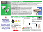
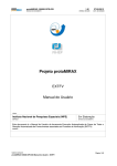
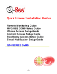
1
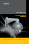
User Manual
MODEL
QH8013Z
Outdoor SDI Pan-Tilt-Zoom Dome Camera with 20x Optical Zoom
1
Introduction
Thank You for Choosing a Q-See Product!
All of our products are backed by a conditional service warranty covering all hardware for 12 months from the date of
purchase. Additionally, our products also come with a free exchange policy that covers all manufacturing defects for one
month from the date of purchase. Permanent upgrading service is provided for the software and is available at www.QSee.com.
Be certain to make the most of your warranty by completing the registration form online. In addition to warranty and
technical support benefits, you’ll receive notifications of product updates along with free downloadable firmware updates
for your DVR. Register today at www.Q-See.com!
Please see the back of this manual for exclusions.
This manual is written for the QH8013Z SDI PTZ camera and was accurate at the time it was completed. However,
because of our ongoing effort to constantly improve our products, additional features and functions may have been added
since that time and on-screen displays may change. We encourage you to visit our website at www.Q-See.com to check
for the latest product announcements. You can also find technical details and an electronic version of this manual on the
QH8013Z’s product page on our site.
Throughout the manual we have highlighted warnings and other important information that will assist you in operating
your new system in a safe and trouble-free manner. Please take the time to read and follow all instructions and pay
attention to alerts as shown below:
IMPORTANT! Red boxes with this icon indicate warnings. To prevent possible injury or
damage to the product, read all warnings before use.
NOTE! Text in blue boxes with the Information icon offer additional guidance and explanations
about how to make the most out of your system.
For your safety and to protect your camera
To prevent damage to your Q-See product or injury to yourself or to others, read and understand the following safety
precautions in their entirety before installing or using this equipment.
WARNING! ELECTRIC SHOCK RISK!
© 2014 Q-See. Reproduction in whole or in part without written permission is prohibited. All rights reserved. This
manual and software and hardware described herein, in whole or in part, may not be reproduced, translated, or reduced
to any machine-readable form without prior written approval.
Trademarks: All brand names and products are trademarks or registered trademarks of their respective owners.
Q-See is a registered trademark of DPS, Inc.
Disclaimer: The information in this document is subject to change without notice. The manufacturer makes no
representations or warranties, either express or implied, of any kind with respect to completeness of its contents.
Manufacturer shall not be liable for any damages whatsoever from misuse of this product.
2
nCare should be taken during transportation, storage and installation of this camera to avoid rough handling, dropping, or
other abuse in order to prevent damage to the optics or components inside the camera.
nCamera should be installed in accordance with electrical standards including keeping the camera and cable away from high
voltage, using a transient voltage surge protector (UL-1449) and using only the rated power supply.
nDo not use strong or abrasive cleaners on camera body or lens. Use a damp cloth for cleaning the housing and a lens cloth
for the optics.
nDo not attempt to disassemble the camera beyond removing the case to adjust settings. Only authorized, trained
technicians should service this camera.
nThe camera should not be immersed in water and should be mounted in a sheltered location. Do not point camera directly
at the sun or other strong light source.
Rev. 1.0 2/3/14
3
FEATURES & SPECIFICATIONS
IMPORTANT! This camera will only work with SDI DVR systems! It will not
work with systems using analog video technology. Your DVR must also
support 1080P resolution.
Product Features
Your camera offers the following features:
n 1080p High Definition resolution
n Weatherproof IP66 rating for indoor and outdoor use
n Built-in heater and fan for continued operation in severe weather.
n Built-in lightning-proof components to prevent damage by lightning strike or power surge.
n Automatic and manual focus
n Automatic and manual white balance
n Automatic brightness controls
n RS485 control with support for Pelco D and Pelco P protocols
n Automatic Day and Night (low light) modes.
n 0.5 lux minimum for color, .01 lux minimum for B&W and .05 lux minimum for DSS
PTZ Module Features
nHorizontal scanning: 360° rotation
n Vertical tilt: 90°
n Manual rotation/tilt speed: .5°-120°/second
n Preset rotation/tilt speed: .up to 400°/second
n 128 preset positions - 80 preset positions and 48 special function settings.
n Preset options for 8 Patrol, 4 Trace, 2 Auto Scan, Auto Pan functions
n 20x optical zoom
n Fully-functional built-in decoder - all data is saved inside of the module to retain settings in case
of power loss.
n Adjustable speed depending on zoom length to ensure clear image
n Baud rate changeable through on screen menu
QH8013Z PTZ SDI Dome Camera Specifications
Image Sensor
1/3” Panasonic CMOS
Image Resolution
1920 x 1080
Lens Size
4.7 mm to 94 mm (20X Optical Zoom)
Angle of View (horizontal)
3° to 58°
Address Range
1-128
On Screen Display
English
Backlight Compensation
Auto
Gain Control
Automatic/Manual
Wide Dynamic Range
Yes
Supported Protocols
Pelco D, Pelco P
Baud Rate
1200b/2400b/4800b/9600b
Preset & Cruise Patterns
128, including: 8 Patrol, 4 Trace, 2 Auto Scan, Auto Pan
Minimum Illumination (in Lux)
Color 0.5/B&W 0.1/ 0.05 DSS On Auto ICR
Connector Types
HD-SDI BNC, Power, RS485, RS422
Compatible Systems
1080P SDI DVRs
Power Supply
24V
Power Consumption
9W (24W Heater on)
Weatherproof
Yes
IP Rating
66
Body Construction
Metal
Mounting Hardware
Screws, wall mount
Weight
11 lbs
Dimensions (WxH)
8.75 x 12.25
Operating Temperature
-4°F – 140°F
Color
White
DEFAULT SETTINGS
Channel/Address: 1
Baud Rate:
9600
Protocol: Pelco P
4
5
PARTS & CONNECTORS
PREPARING YOUR CAMERA
Your camera is packed to protect internal components from damage during shipping. These packing items MUST BE removed before installation or they can interfere with its operation.
5
6
7
8
9
6
1
2
3
4
Use care when handling and opening the camera to avoid damage. Fabric gloves have been
included in order to help prevent smudges and fingerprints on the camera lens or inside the clear
dome.
Loosen the four screws surrounding the camera
dome to remove the camera cover. Use the
included hex wrench.
Do not remove the screws completely from the
camera cover. A retaining wire will keep the
cover attached to the camera body.
x4
Remove the camera pad, lens cap and protecting collar.
1 SDI Video
2Power
3 RS485 Connector
4 RS422 Connector
5 Safety Wire
6 Upper Camera Body
7 Camera Body
8 Retaining Wire
9 Camera Dome
Replace the camera cover making certain that
there are no smudges or debris on the camera
lens or inside the clear dome.
A NOTE ON CAMERA ADDRESS AND COMMUNICATION
Unlike conventional security cameras, PTZ cameras require an address to communicate with the
DVR and operate properly. Unlike analog PTZ cameras, settings on this SDI camera are made
within the camera’s internal menu (covered later in Camera Menu). This camera is set with a
default address of 1, and a baud rate (communication speed) of 9600 and it will use the Pelco P
communication protocol. This means that your camera should be connected to Channel 1 of your
DVR and the baud rate and protocol settings on your DVR should be set to match - at least long
enough for you to change those settings, if desired. The default baud rate of 9600 allows you to
effectively control the camera up to 800 feet away. Areas with electronic interference may require
heavier or shielded cabling. The higher the setting (may be required by some DVRs), the shorter the
control distance.
If you make any changes to the baud rate and
communication protocol within the camera,
you will need to make matching changes in the
DVR itself in order to control the camera without
problem.
NOTE! Some DVRs may require specific
connection speeds. Check your system’s
manual for the proper settings.
7
PTZ CONTROL CONNECTION
CONNECTING THE CAMERA
We recommend connecting your camera to your DVR before mounting it as a “dry run” to make
sure everything is operating normally. It is much easier to correct a situation such as a forgotten
lens cap while the camera is on a table than it is when the camera is mounted high up on a wall. If
you will need to change the camera settings such as address, baud rate or communication protocol, this would be the time to do so (see Camera Menu later in this manual).
POWER AND VIDEO CONNECTION
STEP 1. Connect the BNC and power leads
from the camera to the matching connectors on the included video/power/
control cable.
IMPORTANT! When connecting
the power and video cable between
the camera and the DVR, the “male”
power end connects to the matching
power lead on the camera.
In addition to connecting the power and video leads to the camera, you
must also connect the two control wire leads to the RS485 ports in the
alarm block on the back of the DVR. These blocks can vary in layout
as shown below, but the ports used by your DVR are generally labelled
“RS485”, “PTZ” or “P/Z”. The RS422 connector will not be used.
As seen in the picture on the upper right, the wire leads from the camera
are two different colors and are labelled. They are also pre-installed into a
block which plugs into a matching receptacle on the extension cable. The
control wire leads at the other end of the extension cable must be inserted
into the ports on the back of the DVR. In the case of the RS485 ports
being marked as positive (+) and negative (-), the wire designated RS485A
(red tip) is the positive lead while the wire marked RS485B (yellow tip)
is to go into the negative port. PTZ blocks either have small screws to
above each port to secure the wire or require a lock above the port to be
depressed with an object like a small screw driver in order to fully insert the
wire. In the latter, when the lock is released, an internal clamp will keep the
wire firmly secured in the port. If the wire can easily be removed from the
port, then it isn’t secure and you can experience control difficulties until it
is properly attached. Space permitting, multiple PTZ cameras may be connected to the same ports. They will each require a different address.
If you need to mount the camera further than allowed by the included 100’
STEP 2. Connect the power lead on the other
end of the video/power cable into the
included 24V 2.2A power supply.
STEP 3. Connect the BNC connector on that
same end of the cable to the Video In
port marked 1 on the back of the DVR.
Some examples of PTZ blocks. One using screws (left) and two using spring-loaded locks.
AUDIO IN
1
2
VIDEO IN
3
4
1
2
3
4
You can now plug the camera’s power adapter into a surge protector and turn it on. To protect your
investment, we STRONGLY recommended using a surge protector that is UL-1449 rated, for a
clamping voltage of 330 or lower, a Joule rating of at least 400 and a response time of 10 nanoseconds or less.
8
cable, you will need to get a shielded RG59 video/
power cable that runs the entire didstance and a
pair of 24-gauge wires to connect to the RS485
block. SDI cables should not be extended.
Once you have made your connections, you will
need to make settings on the DVR in order to control it. You will need to consult your DVR’s manual
for this procedure, but a sample screen (from a
Q-See QT-series DVR) is shown on the right.
P.T.Z
Serial Port
Advanced
CH
Address
Baud Rate
1
Enable
1
2400
PELCOD
2
2
9600
Protocol
PELCOP
3
3
9600
PELCOP
4
4
9600
PELCOP
Simulative Cruise
All
9600
PELCOP
Default
Apply
Exit
9
INSTALLING THE CAMERA
MOUNTING THE CAMERA
When installing your camera, it is important to select a proper site not only for field of view, but for
other considerations as well:
STEP 1. Run the power/video/data extension from the DVR to the
camera’s location.
Distance from viewing/recording device. The further the camera is from the DVR or monitor, the
higher the chances of signal degradation. Typical 75Ω Video Cable provides acceptable signal at distances up to 200’ (30m). At greater distances, UL-Listed shielded RG59 should be used. The camera’s power supply should be located as near to the camera as possible when the distance exceeds
200’ as the power level will drop over extended distances resulting in a decrease in video quality.
STEP 2. Use the mounting bracket to mark the position for the
mounting holes. Ensure that the camera will be horizontal
by using a spirit or bubble level. Also mark location of hole
for cables to pass through the mounting surface. This hole
should be large enough to prevent the cable from catching
on anything and allowing the cable extending from the
camera to be easily pushed through.
4
Do not place near high voltage wires or other sources of electrical interference. Electrical
interference will degrade the quality of the signal.
STEP 3. Drill the mounting and cable holes.
Place camera out of reach to avoid damage.
Avoid direct exposure to weather. Do not place the camera where rain or snow will hit the lens
directly nor should the camera be placed so that the sun or bright light shines directly into the lens.
Your camera is weatherproof, but it will not work when submerged in water. Ensure that all power
and video connections are not directly exposed to water and are protected from the elements.
STEP 4. Mount the bracket on the desired surface using the included hardware.
5
Do not place camera behind a window. If there is a light source behind the camera, it can cause
a reflection in the window that will obscure events on the other side of the glass.
Light levels should be approximately the same between camera and target area. A camera
in a brightly-lit area looking into a shaded area, or vice versa, may produce inadequate results.
The above are guidelines and the optimal location
for your camera will depend on your unique circumstances. As a general rule, the locations highlighted in green in the picture to the right indicate
the best locations to mount your camera. Both
locations are sheltered from rain or snow and offer
good sight lines to allow your camera to monitor a
wide area. Because your camera is weatherproof,
it requires less protection than weather-resistant
cameras and it can be placed in more exposed locations if needed. Keep in mind that this camera is
designed to operate between -4°F – 140°F (-20°C
to 60°) with a relative humidity of up to 95%) and
consider wind chill and other environmental factors
when selecting your location.
Your camera comes with a wall mount (a ceiling mount is available separately from q-seestore.com.
Where you locate your camera will determine which mount you will need to use. The mounting surface must be sturdy and able to hold at least five times the camera’s total weight of 11 pounds (5kg).
10
7
8
Depending on your situation, you may want to have the
extension cable leads pulled through the mount to make it
easier to connect to the camera. If you have access to the
other side of the mounting surface, then plan to pull them
through the mount so you can connect to the extension
cable from there.
STEP 5. Attach the mounting collar to the camera body with the
three bolts. Position collar so that safety wire attachment
point faces the rear of the camera. Make sure that the
camera’s cable ends pass through the collar and are not
constricted.
STEP 6. Connect the camera cable leads to the leads on the extension cable and carefully push/pull the cables through the
mount taking care to not pinch or bend cables nor disconnect the leads
STEP 7. Rotate the camera body/collar assembly to screw it onto
the mount.
STEP 8. Clip the safety wire onto the attachment point on the collar.
IMPORTANT! Do not allow the camera cable to be subject to pinching, tight
bends or other severe constriction as part of its final installation position as this
can damage the cable over time leading to signal loss or potential fire hazard.
Take precautions to ensure a clear work area below the camera mounting point during
installation as a falling camera can cause injury or damage.
11
OPERATION WITH DVR
The QH8013Z can be controlled using the PTZ controls on the DVR to which it is connected. In
addition, as covered in the next section, Camera Menu (Page 14), it can be operated using its
own menu. Most users find the DVR operation more convenient because of the ease of access.
Depending on the software used, it is also possible to control the PTZ camera remotely when you
are logged into the DVR via the Internet, a remote monitoring program or a smartphone app.
You can also program a cruise - also called “scan” or “tour” on some systems - so that the camera
will perform a set search pattern of the surrounding area. These settings can be made on the DVR
or in the camera itself. As mentioned in the section on Connecting the Camera, you will need to
consult your DVR’s manual for specifics on how to enable your system to control your camera. That
manual should also contain instructions on how to program points and cruises for the camera to use.
If the DVR channel that your camera is connected to is set to record when motion is detected, the
movement of the camera itself will result in constant recording.
GENERAL CRUISE SETUP PROCEDURE
While each DVR system is different in the specifics of how to set up a scan, there are general
similarities. Most involve the process of pivoting
the camera to the desired starting point and
saving that point. Then, by selecting one or more
points for the camera to move to in sequence,
a scan path is built which is then saved. Often,
multiple paths can be saved within the DVR,
which can be selected for later use.
01 02 03 04 05 06 07 08 All
Zoom
Focus
Iris
No.
1
Save
Speed: 5
These points can be set using a special PTZ
keyboard, or by using the PTZ controls on the
DVR itself. Two such on-screen interfaces are
shown at right; the QT-Series (top) and QCseries (bottom). In both examples, directional
control is achieved by using the DVR’s mouse
to click on one of the directional arrows. As
long as the arrow is held, the camera will move
in that direction. The camera can continuously
rotate full-circle if desired. The camera’s elevation is limited to 90°.
On both control panels there are controls for zoom, focus and iris (light level). The QH8013Z has
a 20x optical zoom lens which will adjust between 4.7 and 94mm. The camera has an auto-focus
feature and can be manually adjusted as well.
Of the 128 presets available on the camera, presets 1-89 may be used for defining camera positions. The remainder are commands for the camera. Of that latter group, Preset 95 allows access
to the camera’s internal menu.
12
EXAMPLE 1: SETTING A CRUISE
This example is based on using a QT-Series DVR without an attached PTZ keyboard. Your DVR’s
specific commands may differ slightly. Please consult your system’s manual.
STEP 1. In your DVR’s PTZ Settings window,
select the Advanced tab and then
Preset 1.
STEP 2. Rotate the camera to the desired position using the arrow controls.
STEP 3. Click Save
STEP 4. Select Preset 2.
STEP 5. Rotate camera to desired second
location.
STEP 6. Click Save
You may repeat Steps 4-6 for additional positions if desired.
STEP 7. Return to the PTZ window and click on
the Cruise button for your channel.
STEP 8. Click Add.
STEP 9. Double-click on the new cruise setting
to begin loading your presets.
STEP 10. Click on the + button to open the
Preset pop-up window and select
your starting preset point, speed and
stop time.
Speed: 1-8 with 8 being the fastest
Time: This is the time the camera will
stay pointed at this location.
STEP 11. Repeat for each preset - up to a
maximum of 16 per cruise.
P.T.Z
Serial Port
CH
Advanced
Preset
Cruise
Track
1
Setting
Setting
Setting
2
Setting
Setting
Setting
3
Setting
Setting
Setting
4
Setting
Setting
Setting
5
Setting
Setting
Setting
6
Setting
Setting
Setting
7
Setting
Setting
Setting
8
Setting
Setting
Setting
Default
Apply
Exit
01 02 03 04 05 06 07 08 All
No.
Zoom
1
Focus
Save
Iris
Speed: 5
01 02 03 04 05 06 07 08 All
Zoom
Start Track
Focus
Preset
Iris
Cruise
preset 101
Start Auto Scan
Start Cruise
Speed: 5
STEP 12. Click OK save your settings and close the windows until you reach the PTZ Settings
window. Click Apply to save all of the settings.
STEP 13. Open the PTZ Controls from the Control Bar, select your cruise in the pull-down and
click
to begin.
EXAMPLE 2: SETTING A TRACK
An alternate method is to utilize the Track settings - also found in the Advanced tab. Click the
Track button for the right channel, use the directional controls to point the camera at your desired
starting point and then click Start Record. The DVR will then record your movements, including
delays at selected spots. Click Stop Record to end. Clicking on Start Track in the PTZ Control
window will start the camera on its track.
13
SYSTEM SETUP WINDOW
CAMERA MENU
The QH8013Z’s internal menu provides another method to control its movements as well as allowing the user to make settings to the camera itself. These settings range from changing the camera’s
address and baud rate to adjusting the color balance, day/night mode and zoom speed.
In your DVR’s PTZ Controls, select Preset
95 in the pull-down and click
to enter the
camera’s internal menu.
01 02 03 04 05 06 07 08 All
Zoom
Start Track
Focus
Preset
Iris
Cruise
preset 101
Start Auto Scan
Start Cruise
As the name says, this is where you will make your
changes to the camera’s general settings.
Auto PT Flip - When this is enabled, and the
camera is programmed to go beyond 90° (straight
down), the camera will quickly rotate so that the
lens will be able to continue to elevate with the
image right side up.
Language Setup - English is the only available
option.
SYSTEM SETUP
1
2
3
4
5
6
7
0
RS422 SETUP
Speed: 5
RS422 Setup - Change your camera’s address,
baud rate and communication protocol.
MENU NAVIGATION
Use the PTZ “up” and “down” directional arrows
to move around in the menu.
Click on the right arrow to:
∙ Select an option from a menu.
∙ Enter a submenu designated by “ ”
∙ To confirm a setting (i.e., clicking Enter)
Move Up
Move
Left
Move Right/
“Enter”
Move Down
The left arrow is used to go back to the menu
item.
To go up one level (i.e.; back to the Main menu
from a submenu), click on Return.
To go up one level (i.e.; back to the Main menu
from a submenu), click on 0 Return.
SYSTEM INFORMATION WINDOW
This window shows the current settings for the
camera. The menu cannot be navigated.
14
MAIN MENU
1
2
3
4
5
6
7
0
SYSTEM INFORMATION
SYSTEM SETUP
CAMERA SETUP
PRESET SETUP
DOME FUNCTION
DISPLAY SETUP
LOAD DEFAULT
EXIT
SYSTEM INFORMATION
1
2
3
4
5
6
7
0
VERSION:
V1.10
CAMERA:
HD20T
TEMPERATURE:72°F
DATE:
01-24-14
DOME ID:
001
PROTOCOL:
PELCO-P
BAUD RATE: 9600
RETURN
Leave “RS422/ID SEL” set to S/W (software).
If you change any of the other settings in this
window, you will have to change the settings in
the DVR to match.
Dome ID - This is the camera’s address. It can
range from 1-255.
AUTO PT FLIP: ON
LANGUAGE SETUP
RS422 SETUP
DATE SETUP
TITLE SETUP
NORTH SETUP
HOME POSITION
EXIT
1
2
3
4
0
RS422/ID SEL:S/W
DOME ID:
001
PROTOCOL:
PELCO-P
BAUD RATE: 9600
EXIT
Date Setup, Title Setup - These will appear on screen (and be recorded by the DVR as part of
the video) only if enabled in the Display Setup option. Your DVR also has the ability to include this
information. If you choose to utilize these, use the directional arrows to navigate through the entries.
When complete, select Preset 001 from the pull down and click
to save it. Or, select Preset
002 and click
to exit out of the menu without saving changes.
North Setup - You can choose a point that the camera will regard as “North”. If enabled in the
Display Setup option, the camera will display its position in degrees from its “North”. In addition to
the horizontal position, the camera will consider 0° (horizontal) as part of the setting and will show
the vertical depression from that point as well.
Home Position - You can cause your camera to return to a specific “Home” position after a set
period of time (5 seconds to 3 minutes). By using this setting, you can have the camera monitor a
specific point until and alarm (set up in the DVR) triggers an action, such as a cruise. Afterwards, it
will return back to its starting point.
The date, time, and position displays will only appear on screen if enabled in the Display Setup
menu (page 20).
15
CAMERA SETUP WINDOW
CAMERA SETUP
Settings affecting the camera’s video image are
located in this menu.
1
2
3
4
5
6
0
CAMERA CONTROL - This submenu contains
settings to maximize image quality.
BLC - Back Light Compensation. This can be
set either On or Off and allows the camera to
digitally adjust the image to make items in the
foreground clearer when there is a bright light
behind them.
HLC - High Light Compensation. When this is
enabled, bright lights, such as headlights, will
be digitally blacked out in order to make other
details clearer. An example would be to see a
license plate that would normally be washed
out by the vehicle’s headlights.
CAMERA CONTROL
IMAGE SETUP
FOCUS NEAR LIMIT: 1M
ZOOM SPEED: MIDDLE
DZOOM:
OFF
PAL/NTSC
NTSC
EXIT
CAMERA CONTROL
1
2
3
4
5
6
7
8
0
HLC Level - Adjusts the level of compensation.
Examples of BLC and HLC are below and
below right:
BLC:
OFF
HLC:
OFF
HLC LEVEL: 20
3D-DNR:
LOW
COLOR LEVEL:08
SHARPNESS: 08
IMAGE FLIP: OFF
GAMMA:
DEFAULT
RETURN
IMAGE CONTROL - This submenu contains more
controls for the camera’s video.
Brightness - Adjust the brightness from dark
(00) to light (20).
AGC - Automatic Gain Control “amplifies” the
image for more detail, but it may be grainy.
Shutter Mode - Manual or Automatic
Shutter - Only active when the shutter is in
manual mode. The lower the value, the brighter
the image.
IMAGE CONTROL
1
2
3
4
5
6
7
8
0
Focus Near Limit - This allows you to set the closest distance that the camera can focus on. This
is useful if there is some item, like part of the building, that the camera will automatically focus upon
at the expense of items in the distance.
Zoom Speed - Adjusts the zoom speed.
Digital Zoom - Allows the camera to electronically zoom beyond the camera’s 20x optical limit up
to 240x. Objects in digitally zoomed video will not be as clear as those in optical zoom.
Video Format - NTSC (Americas) or PAL (Europe, Asia, Brazil, Argentina and Uruguay)
3D-DNR - 3D Digital Noise Reduction reduces
the graininess of images in low-light conditions.
Color Level - Adjusts the on-screen color
levels. Settings range from 1 to 14.
Sharpness - Adjusts image definition. Settings
range from 1 to 20.
Image Flip - The camera’s image can be
flipped horizontally, vertically or both.
Gamma - Adjusts the contrast of the video.
16
If you wish to program your camera’s movements
in the camera rather than the DVR, this menu lets
you set up the preset points.
BLC On
Title Display - You can name preset points if
desired in the Preset Setting, (option 3). This
option lets you display the name on screen.
HLC Off
HLC On
10
05
AUTO
01
ATW
15
15
AUTO
WB Mode - White Balance allows you to adjust to the specific light conditions. Choose from
Auto, Manual and ATW (Automatic Tracking White) where the camera attempts to keep a “neutral” white.
MWB Red Gain/MWB Blue Gain - These two settings are only available when the white balance mode is set to Manual and they affect the red and blue color levels.
Day/Night Mode - The camera will normally adjust between day (color) and night (black and
white) modes automatically based on light levels. However, you can set the camera to operate
permanently in one mode or the other.
PRESET SETUP WINDOW
BLC Off
BRIGHTNESS:
AGC:
SHUTTER MODE:
SHUTTER:
WB MODE: MWB RED GAIN:
MWB BLUE GAIN:
DAY NIGHT MODE:
RETURN
PRESET SETUP
1
2
3
4
5
0
TITLE DISP:
CUR PRESET NO:
PRESET SETTING
DEL CUR PRESET
DEL ALL PRESET
EXIT
OFF
001
CREATING A PRESET POINT
STEP 1. Use the DVR controls to position the camera
STEP 2. Return to the camera’s menu by selecting Preset 95
STEP 3. Set the number of the current preset point (option 2)
STEP 4. Enter the Preset Setting submenu (option 3)
STEP 5. Enter a title, if desired. Select Preset 001 from the DVR’s pull down and click
to save this
point. Or, select Preset 002 and click
to exit out of the menu without saving changes.
17
DOME FUNCTION WINDOW
TASK SETUP - You can designate up to eight
separate periods in a day and assign the camera
specific tanks for each period. If Tasks are enabled, the Home Position function (page 15) will
not operate.
DOME FUNCTION
This menu lets you take the preset points created
in the previous menu and put them together into a
maximum of eight patrols with 16 points each. A
patrol, is the same thing as a cruise on the DVR.
1
2
3
4
5
6
7
0
CREATING A PATROL
STEP 1. Select Patrol Setup
STEP 2. Set the Patrol Number (option 1) You may create up to 8.
STEP 3. Enter the Edit Current Patrol submenu
PATROL SETUP
TASK SETUP
TRACE SETUP
DAY NIGHT
DOME FUNCTION
NEW PASSWORD
CHANGE PASSWORD
RETURN
1
2
3
4
0
PATROL NO: 1
EDIT CUR PATROL
RUN CUR PATROL...
DEL CUR PATROL
RETURN
ALARM SETUP - This is not functional in this camera. For an alarm-triggered action, please use
your DVR’s alarm settings to run a pattern, track or cruise that has been saved in the DVR’s PTZ
controls.
You can navigate between points using the left and
right arrow keys. Use the up and down arrow keys
to change the number values.
Clicking on the Iris + button in the DVR’s PTZ
Control window will increase a number value by
10. Clicking on the Iris - button will decrease the
value by 10.
If you wish to use less than 16 preset points in
your patrol, set the unused points to 000.
Run Current Patrol - This will run the selected
patrol until the camera is instructed to do
otherwise.
Speed: 5
18
TRACE SETUP
This will create a path that the camera will follow, including horizontal and vertical positions along
with zoom and focus settings. This differs from the Patrol in that the camera will record your actions
and save it as a Trace. This is identical to the Track feature on QT-Series DVRs. Each Trace can last
up to 3 minutes. If that time is exceeded, the camera will save the trace
to that
and 05
exit to 06
01 up
02
03point04
the Trace Setup menu.
FORMAT: PRENO/TIME<SEC>
01: 001/005 02: 002/005
03: 003/005 04: 004/005
05: 005/005 06: 006/005
07: 007/005 08: 008/005
09: 009/005 10: 010/005
11: 011/005 12: 012/005
13: 013/005 14: 014/005
15: 015/005 16: 016/005
CALL 1 TO STORE
CALL 2 TO CANCEL
Delete Current Patrol - Deletes the selected
patrol.
TASK SETTING
00:00-00:00 NONE: 00
00:00-00:00 NONE: 00
00:00-00:00 NONE: 00
00:00-00:00 NONE: 00
00:00-00:00 NONE: 00
00:00-00:00 NONE: 00
00:00-00:00 NONE: 00
00:00-00:00 NONE: 00
CALL 1 TO STORE
CALL 2 TO CANCEL
CREATING A TASK
STEP 1. Set a start and end time using 24 hour
(military) time.
STEP 2. Choose a task: Random, Point to Point,
Preset Point, Patrol or Trace.
STEP 3. Select Patrol, etc. you want.
STEP 4. Select Preset 001 from the DVR’s pull down and click
to save this point. Or, select
Preset 002 and click
to exit out of the menu without saving changes.
PATROL SETUP
The 16 available preset points for your patrol
are arranged in two columns with the delay (in
seconds) for that point immediately to its right. You
can have the camera stay on a point between 5
and 240 seconds (4 minutes).
1
2
3
4
5
6
7
8
01 02 03 04 05 06
Zoom
STEP 1. Set the trace number
STEP 2. Select Trace Setting
STEP 3. Click on the Iris - button to begin
recording.
STEP 4. Use the directional, zoom, function and
iris controls to create your trace.
STEP
5.
When
Speed:
07 08 All complete, select Preset 001 from
the DVR’s pull down and click
to
save your trace.
Zoom
Focus
Preset
Iris
Cruise
5
Trace Run- SelectStart
this toTrack
run your Trace.
Focus
Preset
Iris
Cruise
preset 101
Start Auto Scan
DAY/NIGHT
This setting allows you
to set
what time the camera will operate in day (color) mode and night (black
Start
Cruise
and white) mode regardless of the light level. For this to be utilized, you must have set the date and
time in the System Setting menu (see page 15). Select Preset 001 from the DVR’s pull down and
click
to save your settings.
19
p
NEW PASSWORD/CHANGE PASSWORD
These features are not operational on this camera. If you are concerned about the security of your
camera - or your system for that matter - set up specific user accounts for anyone who has access
to your DVR. On QT-series DVRs you can limit user permissions to specific functions. Treat these user
accounts as you would a user account on a computer as far as password difficulty and sharing with
others.
DISPLAY SETUP WINDOW
This is the menu that allows you to enable the time, temperature, position and other displays that
you may have set up in other menus.
LOAD DEFAULT WINDOW
You can reset your camera back to the factory default settings through this menu.
Master Reset - This will reset the camera and active menu but will not clear settings such as the
camera’s name, baud rate, preset points, patrols or etc.
EXTENDING CABLE
Your camera comes with a pre-built 100’ RG59 power/video/data cable. If a longer run is desired, the
included power supply will power the camera up to 300 feet away, but you must use a continuous
shielded RG59 cable without any breaks in it. A communication wire will also need to be run in parallel in order to control the camera.
To maintain video quality:
· SDI video requires the use of shielded cables.
· Always check state and local laws before installing cameras. (2011 NEC 820.44)
Other notes:
· If a cable run exceeds 800ft, we recommend using RG-6 coaxial cable which is available at most
retail building supply companies.
· Cable runs over 300 feet will require a larger camera power supply or for the power supply to be
only 300 feet away from the camera.
Master Clear - Resets the camera and clears all user settings.
System Reboot - Reboots the camera, but does not clear any settings.
Firmware Update - The camera’s firmware can be updated using the RS422 port. This should only
be done using a firmware package provided by Q-See.
CAMERA PRESETS
The commands listed in the first table are hard-wired into the camera. They can be accessed using
the DVR’s PTZ Control window and clicking on
. Those in the second table have multiple functions depending on where they are accessed or set.
20
Preset
Function
Preset
Function
90
Run Trace 1
91
Set Random Scan
91
Run Patrol 1
92
Run Patrol 2
93
Run Patrol 3
94
Run Patrol 4
95
Open camera menu
97
Random scan
98
Point to Point scan
Task: Return to start point
92
Set left border of Point-toPoint scan
93
Set right border of Point-toPoint scan
21
TROUBLESHOOTING
Problem
Cause and Solution
No image or movement when powered
up
Check the power cable for damage and connection
Ensure that the power outlet is live
Q-SEE PRODUCT WARRANTY
Q-See is proud to back all of our products with a conditional service warranty covering all hardware
for 12 months from the date of purchase. Additionally, our products also come with a free
exchange policy that covers all manufacturing defects for one month from the date of purchase.
Permanent upgrading service is provided for the software.
Check the power supply
The image is not stable
The image is blurry
Check that the video connection is secure
Liability Exclusions:
Check the power supply. The camera cannot be
more than 300’ away.
Any product malfunction or abnormalities in operation or damage caused by the following reasons
are not within the free service scope of our company:
Check the camera dome for dirt or smudges
Use a damp, soft cloth to clean the dome. Do not
use abrasive cleaners or solvents. Avoid harsh chemicals including acetone as they may permanently fog
the plastic.
1. Equipment damage caused by improper operation.
2. Improper equipment operation environment and conditions (e.g., improper power, extreme
environmental temperatures, humidity, lightning and sudden surges of electricity).
Video noise
Check for electromagnetic interference near camera
(such as a generator, large refrigeration unit, etc.)
3. Damage caused by acts of nature (e.g., earthquake, fire, etc).
Normal camera startup and self-check
but no image
Check video cable connection.
5. Product sold over 12 months ago.
Normal camera startup and self-check
but no control
Check if RS485 cable is properly connected.
Abnormal camera startup and selfcheck and unstable control
Check that protective foam has been removed
22
4. Equipment damage caused by the maintenance of personnel not authorized by Q-See.
Remove protective lens cap
Check that camera address, baud rate and protocol
are correct and match the settings on the DVR
In order to fulfill the terms of your warranty, you must complete the registration process after
purchasing our product. To do this, simply fill out the User’s Information Card on our website at
www.Q-See.com
Check that you are using correct power supply
23
QUESTIONS OR COMMENTS?
CONTACT US
24/7 Technical Resources,
Knowledge Base and more at
www.Q-See.com/support
Live Support
Mon.-Fri. 6am to 7pm Sat and
Sun 9am to 5pm Pacific time
Digital Peripheral Solutions, Inc.
8015 E. Crystal Drive
Anaheim, CA 92807
24