1
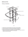
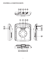
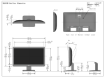
PLVRL6400
OWNER’S MANUAL
FLIP DOWN TFT MONITOR
INSTALLATION
Desk-top Installation
Mounting Bolts (M3x6)
2
1
Tapping Screw (M4x10)
Bracket
Levers
Fig. 1
1. Determine the mounting location and drill four mounting holes.
2. Attach the bracket to the holes with the tapping screws (M4x10).
3. Let the two levers aim at the fixing holes on the bottom of the base to fix the display
unit.
4. Attach the TV unit to the preferred location with the mounting bolts (M3x6).
5. For the convenience of fixing the unit, you can turn the display left or right to show
the holes on the base.
(See the arrowhead symbol named 1).
6. When the installation has completed, you can turn the display upward or downward,
left or right to adjust the viewing angle.
(See the arrowhead symbol named 2 and 1).
2
INSTALLATION
Ceiling-on Installation
Bracket
Levers
Tapping Screws (M4x10)
Fixing holes
Mounting Bolts (M3x6)
Fig. 2
1.
2.
3.
4.
5.
Determine the mounting location and drill four mounting holes.
Attach the bracket to the holes with the tapping screws (M4x10).
Let the two levers aim at the fixing holes to fix the display unit.
Attach the unit to the bracket with the mounting bolts (M3x6).
When the installation has completed, you can also turn the display upward or
downward, left or right to adjust the viewing angle.
(See the arrowhead symbol).
3
REPLACING THE CAR DOME LAMP
Follow the directions show below for a new lamp changing.
1. Position light switch to “ ”.
2. Push back the lamp cover and open it. (Refer to the following figure)
3. Remove and discard the old lamp.
4. Install a new bulb.
5. Close the cover.
Lamp Cover
Bulb
Light Switch
Bulb Specification
Diameter:
ø8mm
Length:
28mm
Voltage Spec.: DC12V, 5W
CAR DOME LAMP WIRING
Line for Car Dome Lamp
Note:
Color
Connection
Red
Power Supply
White
Black
Interior Light Supply
Ground
4
CONTROL & FUNCTION KEYS
1
2
7
4
5
6
8
9
3
11
11
12
12
13
14
18 15 16 19 17
5
CONTROL & FUNCTION KEYS
10
6.4 INCH TFT COLOR MONITOR
6
MONITOR
1.
(=POWER)
Press button (1) to turn on the unit. Press it again to turn it off.
2.
POWER INDICATOR LIGHT
When the system is on, the indicator light (2) will be illuminated.
3.
CAR DOME LAMP
The car dome lamp (3) will be on in some needed situations.
4.
LIGHT SWITCH
The are three seetings for the car dome lamp operation: (OFF), (AUTO), and
(ON), refer to light switch (4).
A.
: To turn off the lamp.
B.
: To make the lamp turned on only when car doors are opened.
C.
: To turn on the lamp.
5.
REMOTE SENSOR
Point the remote control handset to the remote sensor (5).
Press the function keys on the handset to control the unit, it would be worked for
connecting the TV unit or DVD only.
6.
SPEAKER VOLUME CONTROL KNOB
Rotate the knob (6) clockwise or counter-clockwise to increase or decrease the
volume level of the speakerson the base of the unit. When rotate the knob in the
direction of volume decresing to the end, it will turn off the speakers.
7.
BRIGHT ( )
Rotate the bright knob (7) clockwise or counter-clockwise to increase or decrease
the screen brightness.
8.
CONTRAST ( )
Rotate the volume knob (8) clockwise or counter-clockwis to increase or decrease
the contrast lever of the screen display.
9.
COLOR ( )
Rotate the color knob (9) clockwise or counter-clockwis to increase or decrease
the color lever of the screen display.
10. TFT LIQUID CRYSTAL DISPLAY
The 6.4 - inch color TFT LCD (10) can show the current state of the unit.
11. EARPHONE VOLUME CONTROL KNOB
Slide the knob (11) will change the volume of the earphone.
12. JACKS FOR EARPHONE
There are two jacks (12) for earphone. You can connect earphone to any one of
the jacks to receive sound signal.
7
13. PUSH (Monitor Release Button)
Opening the Monitor
Press the PUSH button (13) to eject the screen display from the base at a little
angle. Then you can easily turn the display upward or downward for good
viewing. The monitor also can be adjusted through 30 degree both left and right
from the central viewing position
Closing the Monitor
Return the monitor to the central viewing position. Then push the monitor back
into the monitor base unit until the screen engages with PUSH button (13) .
14. DISPLAY DIRECTION CONTROL SWITCH
The switch (14) should be dialed to DWN side or UP side to adjust the direction
of the picture display and get user's needed viewing effect.
15. DC 12V INPUT
Through this jack (15), provide DC 12V power supply to the unit.
16. SENSOR
When connect DVD unit or another unit to the monitor through these two jacks
(16), you can control the DVD unit or another unit by pointing the remote contorl
handset directly to the remote sensor (5).
17. AV1 IN
The group of jacks (17) is used for AUDIO R in anf AUDIO L in and VIDEO in.
18. AV2 IN
The group of jacks (18) is also used for AUDIO R in anf AUDIO L in and VIDEO in.
19. AV SELECT SWITCH
Slide the switch (19) to “1” side, the AV1 IN (17) group is avaliable; slide the
switch (19) to “2” side, AV2 IN (18) group is avaliable.
www.pyleaudio.com
8
88-T1341-03