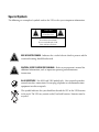
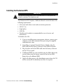
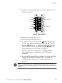
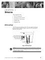
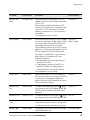
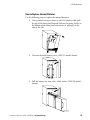
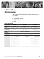
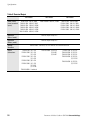
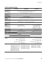
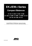
1
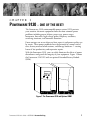
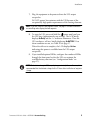
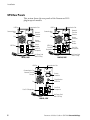
Powerware 9120
®
User's Guide
7003000 VA
www.powerware.com
Requesting a Declaration of Conformity
Units that are labeled with a CE mark comply with the following harmonized standards and EU directives:
Harmonized Standards: EN 50091-1-1 and EN 50091-2
EU Directives: 73/23/EEC, Council Directive on equipment designed for use within certain voltage limits
93/68/EEC, Amending Directive 73/23/EEC
89/336/EEC, Council Directive relating to electromagnetic compatibility
92/31/EEC, Amending Directive 89/336/EEC relating to EMC
The EC Declaration of Conformity is available upon request for products with a CE mark. For copies of the EC
Declaration of Conformity, contact:
Powerware Corporation
Koskelontie 13
FIN-02920 Espoo
Finland
Phone: +358-9-452 661
Fax: +358-9-452 665 68
VCCI Notice for Class A and Class B
(120V and 208V Models)
Powerware is a registered trademark of Powerware Corporation.
Copyright 2001 Powerware Corporation, Raleigh, NC, USA. All rights reserved. No part of this document may be
reproduced in any way without the express written approval of Powerware Corporation.
FCC Part 15
Class A EMC Statements
(20003000 VA Models)
NOTE This equipment has been tested and found to comply with the limits for a Class A digital device, pursuant to
part 15 of the FCC Rules. These limits are designed to provide reasonable protection against harmful interference when
the equipment is operated in a commercial environment. This equipment generates, uses, and can radiate radio frequency
energy and, if not installed and used in accordance with the instruction manual, may cause harmful interference to radio
communications. Operation of this equipment in a residential area is likely to cause harmful interference in which case
the user will be required to correct the interference at his own expense.
ICES-003
This Class A Interference Causing Equipment meets all requirements of the Canadian Interference Causing Equipment
Regulations ICES003.
Cet appareil numérique de la classe A respecte toutes les exigences du Reglement sur le matériel brouilleur du Canada.
EN50091-2
Some configurations are classified under EN500912 as ClassA UPS for Unrestricted Sales Distribution." For these
configurations, the following applies:
WARNING This is a Class AUPS Product. In a domestic environment, this product may cause radio interference, in
which case, the user may be required to take additional measures.
FCC Part 15
Class B EMC Statements
(7001500 VA Models)
NOTE This equipment has been tested and found to comply with the limits for a Class B digital device, pursuant to
part 15 of the FCC Rules. These limits are designed to provide reasonable protection against harmful interference in a
residential installation. This equipment generates, uses and can radiate radio frequency energy and, if not installed and
used in accordance with the instructions, may cause harmful interference to radio communications. However, there is no
guarantee that interference will not occur in a particular installation. If this equipment does cause harmful interference to
radio or television reception, which can be determined by turning the equipment off and on, the user is encouraged to try
to correct the interference by one or more of the following measures:
Reorient or relocate the receiving antenna.
Increase the separation between the equipment and the receiver.
Connect the equipment into an outlet on a circuit different from that to which the receiver is connected.
Consult the dealer or an experienced radio/TV technician for help.
ICES-003
This Class B Interference Causing Equipment meets all requirements of the Canadian Interference Causing Equipment
Regulations ICES003.
Cet appareil numérique de la classe B respecte toutes les exigences du Reglement sur le matériel brouilleur du Canada.
Special Symbols
The following are examples of symbols used on the UPS to alert you to important information:
CAUTION
Risk of Electric Shock
Do Not Open Cover
CAUTION To reduce the risk of electric shock,
Do not remove cover (or back)
No user-serviceable parts inside
Refer servicing to the factory
RISK OF ELECTRIC SHOCK - Indicates that a risk of electric shock is present and the
associated warning should be observed.
CAUTION: REFER TO OPERATOR'S MANUAL - Refer to your operator's manual for
additional information, such as important operating and maintenance
instructions.
RJ-45 RECEPTACLE - For 208V and 230V models only: this receptacle provides
network interface connections. Do not plug telephone or telecommunications
equipment into this receptacle.
This symbol indicates that you should not discard the UPS or the UPS batteries
in the trash. The UPS may contain sealed, leadacid batteries. Batteries must be
recycled.
TABLE OF CONTENTS
1 Powerware 9120 One of the Best! . . . . . . . . . . . . . . . . . . . . . . . . . . . . . . . . . . 1
2 Installation . . . . . . . . . . . . . . . . . . . . . . . . . . . . . . . . . . . . . . . . . . . . . . . . . . . . . 3
Inspecting the Equipment . . . . . . . . . . . . . . . . . . . . . . . . . . . . . . . . . . . . . . . . . . . . . . . . . . . . . . . .
Safety Precautions . . . . . . . . . . . . . . . . . . . . . . . . . . . . . . . . . . . . . . . . . . . . . . . . . . . . . . . . . . . .
Installing the Plug/Receptacle UPS . . . . . . . . . . . . . . . . . . . . . . . . . . . . . . . . . . . . . . . . . . . . . . . . .
UPS Rear Panels . . . . . . . . . . . . . . . . . . . . . . . . . . . . . . . . . . . . . . . . . . . . . . . . . . . . . . . . . . . . . .
Installing the Hardwired UPS . . . . . . . . . . . . . . . . . . . . . . . . . . . . . . . . . . . . . . . . . . . . . . . . . . . . .
3
3
4
6
9
3 Operation . . . . . . . . . . . . . . . . . . . . . . . . . . . . . . . . . . . . . . . . . . . . . . . . . . . . . . 13
UPS Front Panel . . . . . . . . . . . . . . . . . . . . . . . . . . . . . . . . . . . . . . . . . . . . . . . . . . . . . . . . . . . . . .
Display Mode . . . . . . . . . . . . . . . . . . . . . . . . . . . . . . . . . . . . . . . . . . . . . . . . . . . . . . . . . . . . .
Turning the UPS On . . . . . . . . . . . . . . . . . . . . . . . . . . . . . . . . . . . . . . . . . . . . . . . . . . . . . . . . . . . .
Starting the UPS on Battery . . . . . . . . . . . . . . . . . . . . . . . . . . . . . . . . . . . . . . . . . . . . . . . . . . . .
Turning the UPS Off . . . . . . . . . . . . . . . . . . . . . . . . . . . . . . . . . . . . . . . . . . . . . . . . . . . . . . . . . . .
Standby Mode . . . . . . . . . . . . . . . . . . . . . . . . . . . . . . . . . . . . . . . . . . . . . . . . . . . . . . . . . . . . . . .
Diagnostic Tests . . . . . . . . . . . . . . . . . . . . . . . . . . . . . . . . . . . . . . . . . . . . . . . . . . . . . . . . . . . . . .
13
14
14
15
15
15
15
4 Configuration . . . . . . . . . . . . . . . . . . . . . . . . . . . . . . . . . . . . . . . . . . . . . . . . . . . 17
Configuration Mode . . . . . . . . . . . . . . . . . . . . . . . . . . . . . . . . . . . . . . . . . . . . . . . . . . . . . . . . . . . 17
5 Additional UPS Features . . . . . . . . . . . . . . . . . . . . . . . . . . . . . . . . . . . . . . . . . . 21
Remote Emergency Power-Off . . . . . . . . . . . . . . . . . . . . . . . . . . . . . . . . . . . . . . . . . . . . . . . . . . . .
Network Transient Protector . . . . . . . . . . . . . . . . . . . . . . . . . . . . . . . . . . . . . . . . . . . . . . . . . . . . .
Load Segments . . . . . . . . . . . . . . . . . . . . . . . . . . . . . . . . . . . . . . . . . . . . . . . . . . . . . . . . . . . . . . .
Communication Port . . . . . . . . . . . . . . . . . . . . . . . . . . . . . . . . . . . . . . . . . . . . . . . . . . . . . . . . . . .
USB Port . . . . . . . . . . . . . . . . . . . . . . . . . . . . . . . . . . . . . . . . . . . . . . . . . . . . . . . . . . . . . . . . . . .
Communication Slot . . . . . . . . . . . . . . . . . . . . . . . . . . . . . . . . . . . . . . . . . . . . . . . . . . . . . . . . . . .
SNMP/Web Adapter . . . . . . . . . . . . . . . . . . . . . . . . . . . . . . . . . . . . . . . . . . . . . . . . . . . . . . . .
Relay Card . . . . . . . . . . . . . . . . . . . . . . . . . . . . . . . . . . . . . . . . . . . . . . . . . . . . . . . . . . . . . . . .
21
23
24
26
27
27
27
28
6 UPS Maintenance . . . . . . . . . . . . . . . . . . . . . . . . . . . . . . . . . . . . . . . . . . . . . . . 29
UPS and Battery Care . . . . . . . . . . . . . . . . . . . . . . . . . . . . . . . . . . . . . . . . . . . . . . . . . . . . . . . . . . 29
Storing the UPS and Batteries . . . . . . . . . . . . . . . . . . . . . . . . . . . . . . . . . . . . . . . . . . . . . . . . . . 29
Powerware ® 9120 User's Guide 05147426 A Uncontrolled Copy
i
Table of Contents
Replacing Batteries . . . . . . . . . . . . . . . . . . . . . . . . . . . . . . . . . . . . . . . . . . . . . . . . . . . . . . . . . . . .
How to Replace External Batteries . . . . . . . . . . . . . . . . . . . . . . . . . . . . . . . . . . . . . . . . . . . . . . .
How to Replace Internal Batteries . . . . . . . . . . . . . . . . . . . . . . . . . . . . . . . . . . . . . . . . . . . . . . .
Recycling the Used Battery . . . . . . . . . . . . . . . . . . . . . . . . . . . . . . . . . . . . . . . . . . . . . . . . . . . . . .
29
30
31
32
7 Specifications . . . . . . . . . . . . . . . . . . . . . . . . . . . . . . . . . . . . . . . . . . . . . . . . . . 33
8 Troubleshooting . . . . . . . . . . . . . . . . . . . . . . . . . . . . . . . . . . . . . . . . . . . . . . . . . 37
Audible Alarms and UPS Conditions . . . . . . . . . . . . . . . . . . . . . . . . . . . . . . . . . . . . . . . . . . . . . . . . 37
Silencing an Audible Alarm . . . . . . . . . . . . . . . . . . . . . . . . . . . . . . . . . . . . . . . . . . . . . . . . . . . . 37
Service and Support . . . . . . . . . . . . . . . . . . . . . . . . . . . . . . . . . . . . . . . . . . . . . . . . . . . . . . . . . . . 40
ii
Powerware ® 9120 User's Guide 05147426 A Uncontrolled Copy
CHAPTER
1
POWERWARE 9120 ONE OF THE BEST!
The Powerware 9120 uninterruptible power system (UPS) protects
your sensitive electronic equipment from the most common power
problems including power failures, power sags, power surges,
brownouts, line noise, high voltage spikes, frequency variations,
switching transients, and harmonic distortion.
Power outages can occur when you least expect it and power quality can
be erratic. These power problems have the potential to corrupt critical
data, destroy unsaved work sessions, and damage hardware causing
hours of lost productivity and expensive repairs.
With the Powerware 9120, you can safely eliminate the effects of power
disturbances and guard the integrity of your equipment. Figure 1 shows
the Powerware 9120 UPS with an optional Extended Battery Module
(EBM).
Figure 1. The Powerware 9120 and Optional EBM
Powerware ® 9120 User's Guide 05147426 A Uncontrolled Copy
1
Powerware 9120 One of the Best!
Providing outstanding performance and reliability, the Powerware
9120's unique benefits include the following:
The Powerware 9120 incorporates the latest in high-frequency,
double-conversion online topology, which provides uninterrupted,
clean, sine-wave power.
An intuitive LCD screen provides real-time updates of UPS status,
power usage, remaining battery run time, and other critical UPS
parameters.
Flexible communication options with USB, serial, and network
capabilities.
Advanced power management with the Software Suite CD for graceful
shutdowns and power monitoring.
Sequential shutdown and load management through separate
receptacle groups, called load segments.
Network Transient Protector guards your network communications
equipment from surges. Low voltage models can also guard modems,
fax machines, or other telecommunications equipment.
Hotswappable batteries simplify maintenance by allowing you to
replace batteries safely without powering down the critical load.
Startonbattery capability allows you to power up the UPS even if
utility power is not available.
Emergency shutdown control through the Remote Emergency
Power-Off (REPO) port.
The Powerware 9120 is backed by worldwide agency approvals and a
limited two-year warranty.
2
Powerware ® 9120 User's Guide 05147426 A Uncontrolled Copy
CHAPTER
INSTALLATION
2
This section explains:
Equipment inspection
Safety precautions
Plug/receptacle UPS installation and rear panels
Hardwired UPS installation
Inspecting the Equipment
If any equipment has been damaged during shipment, keep the shipping
cartons and packing materials for the carrier or place of purchase and
file a claim for shipping damage. If you discover damage after
acceptance, file a claim for concealed damage.
To file a claim for shipping damage or concealed damage: 1) File with
the carrier within 15 days of receipt of the equipment; 2) Send a copy of
the damage claim within 15 days to your service representative (see
page 40).
Safety Precautions
Read the following precautions before you install the UPS.
IMPORTANT SAFETY INSTRUCTIONS
SAVE THESE INSTRUCTIONS. This manual contains important instructions that you
should follow during installation and maintenance of the UPS and batteries. Please
read all instructions before operating the equipment and save this manual for future
reference.
Powerware ® 9120 User's Guide 05147426 A Uncontrolled Copy
3
Installation
WARNING
This UPS contains its own energy source (batteries). The output receptacles may
carry live voltage even when the UPS is not connected to an AC supply.
Do not remove or unplug the input cord when the UPS is turned on. This removes
the safety ground from the UPS and the equipment connected to the UPS.
To reduce the risk of fire or electric shock, install this UPS in a temperature and
humidity controlled, indoor environment, free of conductive contaminants. Ambient
temperature must not exceed 40°C (104°F). Do not operate near water or excessive
humidity (95% max).
To comply with international standards, the sum of earth leakage current from the
load connected to the UPS must not exceed 1 mA.
NOTE Do not make unauthorized changes to the UPS; otherwise, damage may occur
to your equipment and void your warranty.
Installing the Plug/Receptacle UPS
The following steps explain how to install the UPS. See UPS Rear
Panels" on page 6 for the rear panel of each model.
1. If you are installing power management software, connect your
computer to the UPS communication port using the supplied
communication cable.
2. If installing an optional Extended Battery Module, plug the
EBM cable into the battery connector on the EBM rear panel.
3. Plug the other end of the EBM cable into the battery connector
on the UPS rear panel.
4. If additional EBMs are to be installed, plug the EBM cable of the
second cabinet into the battery connector on the first EBM.
Repeat for each additional EBM.
5. On 208V or 230V models, plug the power cord into the input
connector on the UPS rear panel.
6. Plug the UPS power cord into a power outlet. The fan turns on
and the UPS enters Standby mode.
4
Powerware ® 9120 User's Guide 05147426 A Uncontrolled Copy
Installation
7. Plug the equipment to be protected into the UPS output
receptacles.
DO NOT protect laser printers with the UPS because of the
exceptionally high power requirements of the heating elements.
NOTE If you are using the Load Segment feature, see page 24 for more information
on controlling and assigning the load segments.
8. To start the UPS, press and hold the
button until you hear
the UPS beep (approximately one second). The LCD briefly
displays On Delay and the indicator illuminates. Then the
UPS conducts a selftest, briefly displaying On BATTERY. If an
alarm condition occurs, see Table 10 on page 37.
When the self-test is complete, the LCD displays On Line
indicating that power is available from the UPS output
receptacles.
9. If you installed optional EBMs, configure the number of EBMs
through the front panel so that the UPS can estimate the
available battery run time (see Configuration Mode" on
page 17).
NOTE The batteries charge to 90% capacity in approximately 4 hours. However, it is
recommended that the batteries charge for 6 to 24 hours after installation or long-term
storage.
Powerware ® 9120 User's Guide 05147426 A Uncontrolled Copy
5
Installation
UPS Rear Panels
This section shows the rear panels of the Powerware 9120
plug/receptacle models.
USB Port
Communication Slot
Communication
Port
Network
Transient
Protector
Fan
USB Port
Communication Slot
Network
Transient
Protector
Communication
Port
Fan
Battery
Connector
Battery
Connector
Circuit
Breaker
Four 515
Receptacles
REPO Port
Circuit
Breaker
REPO Port
Two 5-20
Receptacles
Four 515
Receptacles
6-ft Power Cord
with 515 Plug
700 VA, 120V
USB Port
1000 VA, 120V
6-ft Power Cord
with 515 Plug
Communication Slot
Communication Port
Network Transient
Protector
Battery
Connector
Circuit Breaker
Fan
REPO Port
Two 5-20
Receptacles
Four 515 Receptacles
1500 VA, 120V
6
6-ft Power Cord
with 515 Plug
Powerware ® 9120 User's Guide 05147426 A Uncontrolled Copy
Installation
USB Port
Communication Slot
USB Port
Communication Slot
Communication
Network Port
Transient
Protector
Communication
Port
Network
Transient
Protector
Two 5-20
Receptacles
Battery
Connector
REPO Port
Fans
Fans
REPO Port
One L530
Receptacle
Six 5-20
Receptacles
Circuit Breaker
Circuit Breaker
6-ft Power
Cord with
520 Plug
6-ft Power
Cord with
L530 Plug
2000 VA, 120V
USB Port
Four 515
Receptacles
3000 VA, 120V
Communication Slot
Communication
Port
Network
Transient
Protector
Battery
Connector
REPO Port
Fans
Two L6-15R
Receptacles
One L6-20R
Receptacle
One L6-30R
Receptacle
6-ft Power
Cord with
L620 Plug
3000 VA, 208V
Powerware ® 9120 User's Guide 05147426 A Uncontrolled Copy
7
Installation
Communication Slot
USB Port
USB Port
Communication
Port
REPO Port
Communication Slot
Communication
Port
Network
Transient
Protector
Fan
Battery
Connector
Network
Transient
Protector
Fan
Battery
Connector
REPO Port
Four IEC-C13
Receptacles
Four IEC-C13
Receptacles
7001000 VA, 230V
USB Port
IEC-C14 Input
Connector
IEC-C14 Input
Connector
1500 VA, 230V
USB Port
Communication Slot
Communication Slot
Communication
Port
Network
Transient
Protector
Communication
Port
Network
Transient
Protector
Battery
Connector
Battery
Connector
REPO Port
REPO Port
Fans
One IEC-C19
Receptacle
One IEC-C19
Receptacle
Fans
Four IEC-C13
Receptacles
IEC-C20 Input
Connector
IEC-C14 Input
Connector
2000 VA, 230V
8
Four IEC-C13
Receptacles
3000 VA, 230V
Powerware ® 9120 User's Guide 05147426 A Uncontrolled Copy
Installation
Installing the Hardwired UPS
WARNING
Only qualified service personnel (such as a licensed electrician) should perform the
electrical installation. Risk of electrical shock.
The Powerware 9120 requires a dedicated branch circuit that meets the
following requirements:
40A circuit with short circuit and overcurrent protection
100-127 Vac
Single-phase
50/60 Hz
Flexible metal conduit is recommended for ease of service and
maintenance
To hardwire the UPS:
1. If you are installing power management software, connect your
computer to the UPS communication port using the supplied
communication cable.
2. If installing an optional Extended Battery Module, plug the
EBM cable into the battery connector on the EBM rear panel.
3. Plug the other end of the EBM cable into the battery connector
on the UPS rear panel.
4. If additional EBMs are to be installed, plug the EBM cable of the
second cabinet into the battery connector on the first EBM.
Repeat for each additional EBM.
5. Switch off utility power at the distribution point where the UPS
will be connected. Be absolutely sure there is no power.
Powerware ® 9120 User's Guide 05147426 A Uncontrolled Copy
9
Installation
6. Remove the terminal block cover and the wiring knockouts (see
Figure 2). Retain the terminal block cover.
USB Port
Communication Port
Communication Slot
Network
Transient
Protector
Battery
Connector
REPO Port
Fans
Panel Cover Screws
Output Wiring
Access Knockout
Input Wiring
Access Knockout
Terminal Block
Cover
Panel Cover Screws
Figure 2. 3000 VA, 120V Hardwired Rear Panel
7. Pull the input wires through the conduit, leaving approximately
2 ft (0.5m) of exposed wire. Attach a flexible metal fitting to the
end of the conduit.
8. Insert the conduit through the input wiring access knockout
and attach the conduit fitting to the panel. Strip 0.5 (1.5 cm)
of insulation from the end of each incoming wire.
9. Connect the input and ground wires to the input terminal
block (see Figure 3).
10. Pull the output wires through the conduit, leaving
approximately 2 ft (0.5m) of exposed wire. Attach a flexible
metal fitting to the end of the conduit.
11. Insert the conduit through the output wiring access knockout
and attach the conduit fitting to the panel. Strip 0.5 (1.5 cm)
of insulation from the end of each incoming wire.
10
Powerware ® 9120 User's Guide 05147426 A Uncontrolled Copy
Installation
12. Connect the output and ground wires to the output terminal
block (see Figure 3).
Line
Ground
L
Neutral
N
Line
Ground
Neutral
Output Connections
OUTPUT
L
Input Connections
INPUT
N
Figure 3. Terminal Block
13. Replace the terminal block cover.
14. Switch the main utility breaker on.
15. To start the UPS, press and hold the
button until you hear
the UPS beep (approximately one second). The LCD briefly
displays On Delay and the indicator illuminates. Then the
UPS conducts a selftest, briefly displaying On BATTERY. If an
alarm condition occurs, see Table 10 on page 37.
When the self-test is complete, the LCD displays On Line
indicating that power is available from the UPS output
receptacles.
16. If you installed optional EBMs, configure the number of EBMs
through the front panel so that the UPS can estimate the
available battery run time (see Configuration Mode" on
page 17).
NOTE The batteries charge to 90% capacity in approximately 4 hours. However, it is
recommended that the batteries charge for 6 to 24 hours after installation or long-term
storage.
Powerware ® 9120 User's Guide 05147426 A Uncontrolled Copy
11
Installation
12
Powerware ® 9120 User's Guide 05147426 A Uncontrolled Copy
CHAPTER
OPERATION
3
This section describes:
The UPS front panel
Turning the UPS on and off
Starting the UPS on battery
Standby mode
Diagnostic tests
UPS Front Panel
The UPS front panel indicates the UPS status and also identifies
potential power problems. Figure 4 shows the UPS front panel
indicators and controls.
LCD Panel
Power On Indicator (Green)
On Battery Indicator (Yellow)
Bypass Indicator (Yellow)
Alarm Indicator (Red)
Scroll Button
Enter Button
On/Off Button
Figure 4. UPS Front Panel
NOTE If the alarm beeps or if the
indicator is on, see Table 10 on page 37 to
identify and correct the problem. To configure parameters through the front panel, see
Configuration Mode" on page 17.
Powerware ® 9120 User's Guide 05147426 A Uncontrolled Copy
13
Operation
Display Mode
To view the UPS current settings, press the button for one second. Use
the button to scroll through the list of settings:
LCD Message
Description
I/P VOLT= xxx.xV
Input voltage.
I/P FREQ= xx.xHZ
Input frequency.
O/P VOLT= xxx.xV
Output voltage.
O/P FREQ= xx.xHZ
Output frequency.
O/P Load = x%
Approximate percentage of UPS load capacity being used by the
protected equipment.
O/P Watt= xW
Output watts.
O/P VA= xVA
Output VA.
O/P Cur= x.xA
Output current.
BAT VOLT= xx.xV
Battery voltage.
BAT CHARGE= xxx%
Approximate percentage of battery capacity remaining.
BackUp Time= xxxM
Approximate battery time remaining in minutes. The display changes
to seconds after one minute (Backup Time= xxxS).
CPU Version x.xx
Firmware revision level.
NOTE The UPS exits Display mode automatically after five seconds if the
not pressed.
button is
Turning the UPS On
After the UPS is connected to a power source, the fan turns on and
the UPS enters Standby mode. To turn on the UPS, press and hold
button until you hear the UPS beep (approximately one second).
the
The LCD briefly displays On Delay and the indicator illuminates.
Then the UPS conducts a selftest, briefly displaying On BATTERY. If an
alarm condition occurs, see Table 10 on page 37.
When the self-test is complete, the LCD displays On Line indicating that
power is available from the UPS output receptacles.
14
Powerware ® 9120 User's Guide 05147426 A Uncontrolled Copy
Operation
Starting the UPS on Battery
NOTE Before using this feature, the UPS must have been powered by utility power at
least once and the batteries must be completely charged.
To turn on the UPS without using utility power, press and hold
button until you hear the UPS beep (approximately one second).
the
The UPS supplies power to your equipment and goes into Battery mode.
The LCD briefly displays On Delay, then On Battery and the and + indicators illuminate. When the UPS starts on battery, it does not
conduct a selftest to conserve battery power.
Turning the UPS Off
To turn off the UPS, press and hold the
ceases (approximately five seconds).
NOTE When you press and hold the
button until the long beep
button, the LCD displays Shutdown Pending.
The indicator turns off and the LCD briefly displays UPS OFF before
going blank. The fan continues to run and the UPS remains in Standby
mode until you unplug or remove utility power from the UPS.
Standby Mode
When the UPS is turned off and connected to a power source, the UPS is
in Standby mode. The fan continues to run and the battery recharges
when necessary. The indicator is off and the LCD panel is blank,
indicating that power is not available from the UPS.
Diagnostic Tests
The UPS automatically performs a self-test when powered on and when
the UPS restarts after a power outage. The self-test monitors the UPS
electronics and battery and indicates any problems on the front panel.
A battery test is automatically performed every 30 days (720 hours) of
continuous Normal mode operation. The test lasts approximately
15 seconds and any failure is displayed on the front panel.
Both the UPS and battery tests can be performed manually (see
Configuration Mode" on page 17 for more information).
Powerware ® 9120 User's Guide 05147426 A Uncontrolled Copy
15
Operation
16
Powerware ® 9120 User's Guide 05147426 A Uncontrolled Copy
CHAPTER
4
CONFIGURATION
This section describes how to reconfigure options using the
Configuration mode, including: input and output voltage and
frequency, site wiring fault, and silencing the alarm.
NOTE The UPS has been factory-configured with default settings appropriate for most
installations. User configuration is not normally required.
Configuration Mode
The control buttons ( and ) are used to modify the UPS
configuration. Figure 5 shows the front panel and Table 1 explains
the corresponding options.
NOTE The UPS can be configured while in Battery mode. If the UPS switches to
battery power while in Configuration mode, the UPS exits Configuration mode and
indicates Battery mode on the front panel.
1. Press the button for one second to enter Configuration mode.
The LCD displays the first configuration parameter (see
Table 1).
2. Press the button to scroll through the parameters.
NOTE The UPS exits Configuration mode automatically after five seconds if a
selection has not been made.
3. Press the
button to select the parameter.
4. Press the button to scroll through the options for the selected
parameter; press the button to select the option.
You may be prompted to save the selection; press the button
to save. Other options are saved automatically. See Table 1 for
more detail.
Powerware ® 9120 User's Guide 05147426 A Uncontrolled Copy
17
Configuration
5. To exit Configuration mode at any time, do not press any
buttons for five seconds. The UPS returns to Normal mode and
displays On Line.
LCD Panel
Press the Scroll button to enter
Configuration mode. Also press
to scroll to the next option.
Press the Enter button to select a
parameter. Also press the Enter button to
select an option and to save the setting.
Figure 5. Using the Configuration Mode
Table 1. Configuration Mode Parameters
Parameter
LCD Message
Description
Default Settings
Output Voltage
Setting
O/P V Setting
To change the output voltage:
Select 100, 110, 120, or 127V for 120V models.
Select 200, 208, 220, 230, or 240V for 208V models.
Select 208, 220, 230, or 240V for 230V models.
You are prompted to save this setting.
For 120V models:
O/P V= 120V
For 208V models:
O/P V= 208V
For 230V models:
O/P V= 230V
Input Voltage
Tolerance
I/P Bypass Set
Select the input voltage tolerance range before the
UPS goes to Battery mode: ±10%, +10%/-15%, or
+15%/-20%.
You are prompted to save this setting.
I/P Tol=+10%/-15%
Input Voltage
Frequency
I/P F Setting
The factory-default is 50 or 60 Hz, ±5%. Select ±2%
for a narrower frequency range. Select ±7% for a
wider frequency range.
You are prompted to save this setting.
Freq Tol.=+/-15%
18
Powerware ® 9120 User's Guide 05147426 A Uncontrolled Copy
Configuration
Parameter
LCD Message
Description
Default Settings
High-Efficiency
Mode
HE Mode Setting
Select whether High-Efficiency mode is On or Off. If
enabled, you must also select the input voltage range:
±10% or ±15%.
While operating in High-Efficiency mode, the UPS
transfers to utility power when: 1) the input voltage is
outside ±10% or ±15% from nominal; 2) the input
frequency is greater than ±3%; or 3) the input line is
not available.
You are prompted to save this setting.
HE Mode Off
Free Run Mode
Free Run Mode
Select whether Free Run mode is On or Off. If enabled,
you must also select Bypass Disable or Bypass Enable.
This selection defines how your UPS runs when the
input frequency (from the utility) is outside the
selected frequency tolerance (set via the I/P F Setting,
above), but is inside the maximum frequency limits the
UPS can accept before switching to Battery mode.
For example: If your 60 Hz UPS is set to the factory
default window of ±5% before the UPS starts
regulating the frequency:
The output frequency tracks the input frequency
exactly from 57 to 63 Hz.
If input frequency is between 45 and 57 Hz, or
between 63 and 65 Hz, the output frequency is
regulated by the UPS to exactly 60 Hz (±0.5 Hz).
You are prompted to save this setting.
Free Run On
(Bypass Disable)
Alarm Silence
Alarm Silence
Select whether Silence is On or Off. If enabled, the
UPS silences the alarm for an existing fault. If the UPS
status changes, the alarm beeps, overriding the
previous alarm silencing. The alarm does not silence if
there is a low battery condition.
Silence Off
Manual Battery
Test
Manual Bat Test
To initiate a manual battery test, press the button
twice. During the test, the LCD displays On BATTERY.
The UPS resets the automatic timer after a manual
battery test.
Battery Test
Manual UPS Test
Manual UPS Test
To initiate a manual UPS self-test, press the button
twice. During the test, the LCD displays On BATTERY.
UPS Test
Site Wiring Fault
Alarm
Site Fault Set
Select Enable or Disable. When enabled, the alarm
sounds when the ground connection is missing or the
line and neutral wires are reversed in the wall outlet.
Detect Enable
Modem Support
Modem Support
This parameter is reserved for future use, and should
not be modified by the user.
No Modem Support
Powerware ® 9120 User's Guide 05147426 A Uncontrolled Copy
19
Configuration
Parameter
LCD Message
Description
Default Settings
Number of
Extended Battery
Modules
Bat Pack Num Set
Select the number of EBMs connected to the UPS:
For 7001500 VA models, select 0 through 2.
For 20003000 VA models, select 0 through 5.
You are prompted to save this setting.
Extern Pack: 0
Communications
Lock-out
COM Control Cmds For greater levels of security, users may choose to
have the UPS disregard shutdown commands that
come from the power management software or other
communication sources.
When disabled, the UPS does not accept a shut
down command via the communication port, USB
port, or communication slot adapter.
When enabled, the UPS operates normally in
response to external commands.
You are prompted to save this setting.
Enable
Load Segment
Control
Load Group Set
Group 1On 2On
Manual Bypass
Manual Bypass GO This parameter is used to manually place the UPS in
Bypass mode.
Configuration Mode Config Mode Set
Setting
20
Allows manual control of load segments (see Load
Segments" on page 24).
By repeatedly pressing the scroll button, the individual
load segments can be turned on and off.
CAUTION To prevent the unintentional shutdown of
specific load segments, confirm your selection before
pressing the button.
This parameter is reserved for future use, and should
not be modified by the user. The setting may be
toggled between EscapeConfigMode and Enter
ConfigMode. It should always be set to
EscapeConfigMode.
Bypass OFF
EscapeConfigMode
Powerware ® 9120 User's Guide 05147426 A Uncontrolled Copy
CHAPTER
5
ADDITIONAL UPS FEATURES
This section describes:
Remote Emergency Power-Off
Network Transient Protector
Load segments
Using the communication port or USB port
Optional Powerware Corporation communication cards
Remote Emergency Power-Off
The Powerware 9120 includes a REPO port that allows power to be
switched off at the UPS output connections from a customer-supplied
switch in a remote location.
The REPO feature shuts down the protected equipment immediately,
whether or not the UPS is in Normal or Battery mode, and does not
follow the orderly shutdown procedure initiated by any power
management software. The UPS switches to Standby mode.
When the external REPO switch is re-closed, the UPS must be manually
restarted to provide power to the connected equipment.
button is pressed after the REPO is activated, the UPS remains
If the
button is pressed again.
in Standby mode when restarted until the
WARNING
The REPO circuit is an IEC 60950 safety extra low voltage (SELV) circuit. This circuit
must be separated from any hazardous voltage circuits by reinforced insulation.
CAUTION
To ensure the UPS stops supplying power to the load during any mode of operation,
the input power must be disconnected from the UPS when the emergency power-off
function is activated.
NOTE The REPO function activates when the REPO contacts open.
Powerware ® 9120 User's Guide 05147426 A Uncontrolled Copy
21
Additional UPS Features
Use the following procedure to install the REPO switch:
1. Verify that the UPS is off and unplugged or removed from
utility power.
2. Unscrew and remove the REPO connector from the mating
plug on the UPS rear panel.
3. Remove the short wire from the REPO connector.
4. Connect isolated, normallyclosed, dry contacts (rated at
60 Vdc maximum, 30 Vac RMS maximum, and 20 mA
maximum) across the REPO device to Pin 1 and Pin 2 (see
Figure 6). Use stranded, nonshielded wiring, size 1822 AWG
(0.75 mm 20 mm2). See Figure 7.
Pin 1
Pin 2
Figure 6. REPO Connector
REPO Connector
Normally Closed,
Isolated Switch
Powerware 9120 UPS
Figure 7. REPO Wiring Diagram
5. Reconnect the REPO connector to the REPO port on the UPS
rear panel.
6. Verify that the externally-connected REPO switch is closed to
enable power to the UPS output connections.
7. Connect the UPS to a power source.
22
Powerware ® 9120 User's Guide 05147426 A Uncontrolled Copy
Additional UPS Features
8. To start the UPS, press and hold the
button until you hear
the UPS beep (approximately one second).
9. Open the external REPO switch to test the REPO function.
10. Close the external REPO switch and restart the UPS.
Network Transient Protector
The Network Transient Protector, shown in Figure 8 and Figure 9, is
located on the rear panel and has jacks labeled IN and OUT. This feature
accommodates a single RJ45 (10BaseT) network connector.
Low voltage models can also accommodate an RJ11 telephone
connector that provides protection for modems, fax machines, or other
telecommunications equipment. As with most modem equipment, it is
not advisable to use this jack in digital PBX (Private Branch Exchange)
environments.
Connect the input connector of the equipment you are protecting to the
jack labeled IN. Connect the output connector to the jack labeled OUT.
IN
IN
OUT
OUT
NETWORK TRANSIENT PROTECTOR
Figure 8. Network Transient Protector (120V and 208V Models)
IN
OUT
IN
OUT
NETWORK TRANSIENT PROTECTOR
Figure 9. Network Transient Protector (230V Models)
Powerware ® 9120 User's Guide 05147426 A Uncontrolled Copy
23
Additional UPS Features
Load Segments
Load segments are sets of receptacles that can be controlled by power
management software (such as Powerware's Software Suite CD),
providing an orderly shutdown and startup of your equipment. For
example, during a power outage, you can keep key pieces of equipment
running while you turn off other equipment. This feature allows you to
save battery power. See your power management software manual for
details.
The individual load segments can also be turned on and off through the
front panel (see Configuration Mode" on page 17).
Figure 10 and Figure 11 show the load segments for all plug/receptacle
models.
Load
Segment 1
Load
Segment 2
Load
Segment 1
700 VA, 120V
1000 VA, 120V
Load
Segment 2
1500 VA, 120V
Load
Segment 2
Load
Segment 1
Load
Segment 2
2000 VA, 120V
Load
Segment 2
Load
Segment 1
Load
Segment 1
Load
Segment 2
Load
Segment 1
3000 VA, 120V
3000 VA, 208V
Figure 10. 120V and 208V Model Load Segments
24
Powerware ® 9120 User's Guide 05147426 A Uncontrolled Copy
Additional UPS Features
Load
Segment 1
Load
Segment 2
Load
Segment 1
Load
Segment 2
1500 VA, 230V
7001000 VA, 230V
Load
Segment 1
Load
Segment 1
Load
Segment 2
Load
Segment 2
2000 VA, 230V
3000 VA, 230V
Figure 11. 230V Model Load Segments
Powerware ® 9120 User's Guide 05147426 A Uncontrolled Copy
25
Additional UPS Features
Communication Port
To establish communication between the UPS and a computer, connect
your computer to the UPS communication port using the supplied
communication cable.
When the communication cable is installed, power management
software can exchange data with the UPS. The software polls the UPS for
detailed information on the status of the power environment. If a power
emergency occurs, the software initiates the saving of all data and an
orderly shutdown of the equipment.
The cable pins are identified in Figure 12 and the pin functions are
described in Table 2.
5
4
9
3
8
2
7
1
6
Figure 12. Communication Port
Table 2. Communication Port Pin Assignment
26
Pin
Number
Signal Name
Function
Direction from
the Multi-Port
Module
1
Low Batt
Low Battery relay contact
Out
2
RxD
Transmit to external device
Out
3
TxD
Receive from external device
In
RS-232 low
level signal for
>0.4 seconds
Conditional Power Off: In absence of AC
power, output is turned off until normal AC
power returns
In
4
No Connection
5
GND
Signal Ground
6
No Connection
7
No Connection
8
AC Fail
AC Fail relay contact
Out
9
Power Source
+V (8 to 24 volts DC power)
Out
Powerware ® 9120 User's Guide 05147426 A Uncontrolled Copy
Additional UPS Features
USB Port
The UPS is also equipped with a USB communication port. Either the
DB-9 communication port or the USB port may be used to monitor the
UPS; however, they cannot operate simultaneously. Refer to the power
management software instructions for using the USB port.
Communication Slot
The Powerware 9120 UPS has a communication slot that allows quick
installation of the optional SNMP/Web adapter or other similar
communication interfaces. These interface adapters extend the
capabilities of the Powerware 9120 system to provide compatibility with
network and remote monitoring/management systems.
SNMP/Web Adapter
This adapter provides the Powerware 9120 system with its own ethernet
network connection, allowing it to be remotely monitored and
controlled via industry-standard internet browsers. The HTML interface
enables UPS monitoring and management from anywhere on the
internet or within your intranet. In addition, third-party Simple
Network Management Protocol (SNMP) software packages may also be
used to communicate remotely with the Powerware 9120 system.
Powerware ® 9120 User's Guide 05147426 A Uncontrolled Copy
27
Additional UPS Features
Relay Card
This interface provides true relay contact output to peripheral devices.
Outputs are user-selectable as normally open or normally closed.
Table 3. Relay Card (AS/400) Pin Assignment
28
Pin Number Signal Name
Definition
Direction
1
UPS Fail
Relay contact; normally open, closes
when UPS fails.
Out
2
Summary Alarm
Relay contact; normally open, closes
when UPS fails, bypass is activated,
utility power failure, or low battery
status.
Out
3
Remote Shutdown (-)
Ground
4
Remote Shutdown (+)
Activated by +5 to +12V for one second
In
5
Common
Relay common connection for pins 1, 2,
6, 7, 8, and 9.
6
Bypass
Relay contact; normally open, closes
when the UPS is in Bypass mode.
Out
7
Low Batt
Low Battery relay contact; normally
open, closes when the battery is almost
discharged.
Out
8
Battery Mode
Remote Shutdown
Activated by +5 to +12V for one second.
In
9
AC Fail
AC Fail relay contact; normally open,
closes when utility power fails.
Out
Powerware ® 9120 User's Guide 05147426 A Uncontrolled Copy
CHAPTER
6
UPS MAINTENANCE
This section explains how to:
Care for the UPS and batteries
Replace the batteries
Recycle used batteries
UPS and Battery Care
For the best preventive maintenance, keep the area around the UPS
clean and dustfree. If the atmosphere is very dusty, clean the outside of
the system with a vacuum cleaner.
For full battery life, keep the UPS at an ambient temperature of
25°C (77°F).
Storing the UPS and Batteries
If you store the UPS for a long period, recharge the battery every
10 months by connecting the UPS to a power source. The batteries
charge to 90% capacity in approximately 4 hours. However, it is
recommended that the batteries charge for 6 to 24 hours after long-term
storage.
Replacing Batteries
With the hotswappable battery feature, UPS batteries can be replaced
easily without turning the UPS off or disconnecting the load.
If you prefer to remove input power to change the battery, press and
button until the long beep ceases (approximately five
hold the
seconds). Then unplug or remove utility power from the UPS.
Consider all warnings, cautions, and notes before replacing batteries.
Powerware ® 9120 User's Guide 05147426 A Uncontrolled Copy
29
UPS Maintenance
WARNING
Batteries can present a risk of electrical shock or burn from high short circuit
current. The following precautions should be observed: 1) Remove watches, rings,
or other metal objects; 2) Use tools with insulated handles; 3) Do not lay tools or
metal parts on top of batteries.
ELECTRIC ENERGY HAZARD. Do not attempt to alter any battery wiring or
connectors. Attempting to alter wiring can cause injury.
Replace batteries with the same number and type of batteries as originally
installed in the UPS.
DO NOT DISCONNECT the batteries while the UPS is in Battery mode.
How to Replace External Batteries
Use the following steps to replace external batteries:
1. Unplug the EBM cable from the UPS and the old battery.
2. Remove the old battery. See Recycling the Used Battery" on
page 32 for proper disposal.
3. Plug the EBM cable into the battery connector on the new
battery.
4. Plug the other end of the EBM cable into the UPS as shown in
Figure 13.
EBM
Battery
Connectors
UPS Battery
Connector
EBM
Cable
Figure 13. External Battery Connections (120V Model Shown)
30
Powerware ® 9120 User's Guide 05147426 A Uncontrolled Copy
UPS Maintenance
How to Replace Internal Batteries
Use the following steps to replace the internal batteries:
1. Using caution not to put stress on the LCD display cable, pull
the top of the front panel forward. Release the spring latches at
the bottom of the front panel and remove it, placing it to the
side of the UPS.
2. Unscrew the metal battery cover (1000 VA model shown).
3. Pull the battery out onto a flat, stable surface (1000 VA model
shown).
Powerware ® 9120 User's Guide 05147426 A Uncontrolled Copy
31
UPS Maintenance
4. Remove the old battery. See Recycling the Used Battery" for
proper disposal.
5. Install the new battery.
6. Reinstall the metal battery cover and front panel.
Recycling the Used Battery
Contact your local recycling or hazardous waste center for information
on proper disposal of the used battery.
WARNING
Do not dispose of the battery or batteries in a fire. Batteries may explode. Proper
disposal of batteries is required. Refer to your local codes for disposal
requirements.
Do not open or mutilate the battery or batteries. Released electrolyte is harmful to
the skin and eyes. It may be toxic.
CAUTION
Do not discard the UPS or the UPS batteries in the trash. This product contains sealed,
leadacid batteries and must be disposed of properly. For more information, contact
your local recycling or hazardous waste center.
32
Powerware ® 9120 User's Guide 05147426 A Uncontrolled Copy
CHAPTER
7
SPECIFICATIONS
This section provides the following specifications for the Powerware
9120 models:
Electrical input and output
Environmental and safety
Weights and dimensions
Battery
Table 4. Electrical Input
Nominal
Voltage
Voltage Range
120V Models
208V Models
230V Models
120V default;
100, 110, 120, 127V selectable
208V default;
200, 208, 220, 230 240V selectable
230V default;
208, 220, 230 240V selectable
80144V for
100, 110, 120, 127V nominal
Nominal
Frequency
Noise Filtering
Connections
160276V for
200, 208, 220, 230, 240V nominal
160276V for
208, 220, 230, 240V nominal
50/60 Hz, ±5% user-selectable
MOVs and line filter for normal and common mode noise
PW9120 700: 6-ft, 5-15P
power cord
PW9120 1000: 6-ft, 5-15P
power cord
PW9120 1500: 6-ft, 5-15P
power cord
PW9120 2000: 6-ft, 5-20P
power cord
PW9120 3000: 6-ft, L5-30P
power cord
PW9120 3000H: Hardwired
PW9120 3000B: 6-ft, L6-20P
power cord
Powerware ® 9120 User's Guide 05147426 A Uncontrolled Copy
PW9120 700i: 10A, IEC-C14
input connector
PW9120 1000i: 10A, IEC-C14
input connector
PW9120 1500i: 10A, IEC-C14
input connector
PW9120 2000i: 10A, IEC-C14
input connector
PW9120 3000i: 16A, IEC-C20
input connector
33
Specifications
Table 5. Electrical Output
120V Models
Power Levels
(rated at nominal
inputs)
PW9120 700:
PW9120 1000:
PW9120 1500:
PW9120 2000:
PW9120 3000:
PW9120 3000H:
700 VA, 490W
1000 VA, 700W
1500 VA, 1050W
2000 VA, 1400W
3000 VA, 2100W
3000 VA, 2100W
208V Models
PW9120 3000B: 3000 VA, 2100W
Regulation
(Normal mode)
Nominal output voltage ±2%
Regulation
(Battery mode)
Nominal output voltage ±3%
Voltage
Waveform
Output
Connections
34
230V Models
PW9120 700i:
PW9120 1000i:
PW9120 1500i:
PW9120 2000i:
PW9120 3000i:
700 VA, 490W
1000 VA, 700W
1500 VA, 1050W
2000 VA, 1400W
3000 VA, 2100W
Normal mode: Sine wave; <5% THD with full PFC and nonlinear load
PW9120 700: (4) 5-15R
PW9120 1000: (4) 5-15R,
(2) 5-20R
PW9120 1500: (4) 5-15R,
(2) 5-20R
PW9120 2000: (6) 5-20R
PW9120 3000: (4) 5-15R,
(2) 5-20R,
(1) L5-30R
PW9120 3000H: Hardwired
PW9120 3000B: (2) L6-15R,
(1) L6-20R,
(1) L6-30R
PW9120 700i:
PW9120 1000i:
PW9120 1500i:
PW9120 2000i:
(4) IEC-C13
(4) IEC-C13
(4) IEC-C13
(4) IEC-C13,
(1) IEC-C19
PW9120 3000i: (4) IEC-C13,
(1) IEC-C19
Powerware ® 9120 User's Guide 05147426 A Uncontrolled Copy
Specifications
Table 6. Environmental and Safety
120V Models
208V Models
230V Models
Operating
Temperature
0°C to 40°C (32°F to 104°F) 01500 meters above sea level
0°C to 35°C (32°F to 95°F) 15003000 meters above sea level
Optimal battery performance: 25°C (77°F)
Storage
Temperature
-15°C to 50°C (-5°F to 131°F)
Relative Humidity
095% noncondensing
Operating
Altitude
Up to 3,000 meters (10,000 ft) above sea level
Audible Noise
7001500 VA: Less than 48 dBA Normal mode, typical load
20003000 VA: Less than 54 dBA Normal mode, typical load
Surge
Suppression
ANSI C62.41 Category B (formerly IEEE 587)
Safety
Conformance
UL 1778, UL 497A;
CAN/CSA C22.2, No. 107.1
UL 1778 (7002000 Models),
UL 497A (data line only);
CAN/CSA C22.2, No. 107.1
EN 50091-1-1 and IEC 60950;
UL, cUL
UL, cUL, CE, C-Tick
FCC Part 15, ICES-003, VCCI
EN 50091-2, FCC Part 15, ICES-003
Agency Markings
EMC
Table 7. Weights and Dimensions
Extended Batteryy Module Models
UPS Models
120/208V Models
Dimensions
(WxDxH)
Weight
230V Models
7001000 VA: 6.2 x 16.2 x 9.6
(15.8 x 41.2 x 24.3 cm)
1500 VA: 6.7 x 17.5 x 10.8
(17.0 x 44.4 x 27.5 cm)
20003000 VA: 8.6 x 18.6 x 14.2
(21.7 x 47.2 x 36.1 cm)
PW9120 700:
PW9120 1000:
PW9120 1500:
PW9120 2000:
PW9120 3000:
PW9120 3000H:
PW9120 3000B:
29 lb (13.2 kg)
35.5 lb (16.1 kg)
46.5 lb (21.1 kg)
82 lb (37.2 kg)
89 lb (40.5 kg)
89 lb (40.5 kg)
85 lb (38.5 kg)
PW9120 700i:
PW9120 1000i:
PW9120 1500i:
PW9120 2000i:
PW9120 3000i:
Powerware ® 9120 User's Guide 05147426 A Uncontrolled Copy
7001000 VA: 6.2 x 16.2 x 9.6
(15.8 x 41.2 x 24.3 cm)
1500 VA: 6.7 x 17.5 x 10.8
(17.0 x 44.4 x 27.5 cm)
20003000 VA: 8.6 x 18.6 x 14.2
(21.7 x 47.2 x 36.1 cm)
28 lb (12.6 kg)
34 lb (15.3 kg)
44 lb (19.8 kg)
81.6 lb (37 kg)
85 lb (38.5 kg)
PW9120 BAT-700:
PW9120 BAT-1000:
PW9120 BAT-1500:
PW9120 BAT-3000:
31 lb (14 kg)
44 lb (20 kg)
57 lb (26 kg)
110 lb (50 kg)
35
Specifications
Table 8. Battery
Configuration
700 VA: (2) 12V, 7 Ah internal batteries; 24 Vdc
1000 VA: (3) 12V, 7 Ah internal batteries; 36 Vdc
1500 VA: (4) 12V, 7 Ah internal batteries; 48 Vdc
20003000 VA: (8) 12V, 7 Ah internal batteries; 96 Vdc
EBM Configuration
PW9120 BAT-700: (4) 12V, 27 Ah; 24 Vdc
PW9120 BAT-1000: (6) 12V, 27 Ah; 36 Vdc
PW9120 BAT-1500: (8) 12V, 27 Ah; 48 Vdc
PW9120 BAT-3000: (16) 12V, 27 Ah; 96 Vdc
Type
Sealed, maintenancefree, valveregulated, leadacid
Charging
Approximately 4 hours to 90% usable capacity at nominal line voltage after full load discharge
Table 9. Battery Run Times (in Minutes)
Number of Batteries
Run Times at Full/Half Load by UPS VA Ratings
700 VA
1000 VA
1500 VA
2000 VA
3000 VA
UPS Internal Batteries
7/18
7/18
7/18
12/34
6/15
1 EBM
34/70
36/80
29/67
49/107
30/70
2 EBMs
64/140
66/155
56/130
93/195
58/128
3 EBMs
141/310
87/191
4 EBMs
192/403
120/264
5 EBMs
240/504
148/325
NOTE Battery times are approximate and vary depending on the load configuration and battery charge.
36
Powerware ® 9120 User's Guide 05147426 A Uncontrolled Copy
CHAPTER
8
TROUBLESHOOTING
This section explains:
UPS alarms and conditions
How to silence an alarm
Service and support
Audible Alarms and UPS Conditions
The UPS has an audible alarm feature to alert you of potential power
problems. When the alarm is activated, the UPS beeps in different
intervals according to a particular condition. Use Table 10 to determine
and resolve the UPS alarms and conditions.
Silencing an Audible Alarm
There are two ways to silence the alarm for an existing fault:
Press one of the front panel control buttons ( ,
, or ).
Turn the Alarm Silence option on through the front panel (see
Configuration Mode" on page 17).
If UPS status changes, the alarm beeps, overriding the previous alarm
silencing. The alarm does not silence if there is a low battery condition.
Table 10. Troubleshooting
LCD Message or
Condition
Possible Cause
Action
UPS does not turn on.
The UPS is not correctly
connected to the power source.
Check connections to the power source.
The wall outlet is faulty.
Have a qualified electrician test and repair the outlet.
The REPO connector is missing
or open.
Reconnect or close the REPO switch (see page 22). Restart
the UPS.
A circuit breaker or an input
fuse on the rear panel is open.
Push the circuit breaker button or replace the fuse. Restart
the UPS.
Powerware ® 9120 User's Guide 05147426 A Uncontrolled Copy
37
Troubleshooting
LCD Message or
Condition
Possible Cause
Action
LCD panel is blank.
The UPS is in Standby mode.
Press and hold the
button until your hear the UPS beep
(approximately one second).
The LCD has failed.
Contact your service representative.
UPS does not provide the The battery may be fully
discharged because of:
expected backup time.
long-term storage
frequent power outages
end of battery life
Connect the UPS to a power source for 24 hours to charge
the battery. Perform a battery test (see Configuration
Mode" one page 17). If the battery test fails, see Replacing
Batteries" on page 29 to replace the battery.
During extended power outages, save your work and turn off
your equipment to conserve battery power.
The UPS operates
normally, but some or all
of the protected
equipment is not on.
The equipment is not connected
to the UPS.
Verify that the equipment is properly connected to the UPS.
The output circuit breaker (if
applicable) is open.
Reset the circuit breaker (push the circuit breaker button or
reset the switch).
One of the load segments has
been turned off.
Reactivate the segment with the power management
software or through the front panel (see Configuration
Mode" one page 17).
On-Battery
1 beep every 5 seconds.
Utility power failure.
The UPS is powering your equipment with its internal
battery. If this is an extended power outage, save your work
and turn off your equipment to conserve battery power.
Low Battery
2 beeps every 5 seconds.
The battery is running low.
2 minutes or less of battery power remains (depending on
load and battery charge).
Prepare for a shutdown. Save your work and turn off your
equipment. The alarm cannot be silenced.
Replace Battery
3 beeps every 5 seconds.
The battery needs replacing.
See Replacing Batteries" on page 29 to replace the battery.
Low Charge
3 beeps every 5 minutes.
The battery voltage is low.
The UPS is charging the batteries and may not deliver full
run time. The alarm continues until at least two minutes of
run time is available.
Output Overload
2 beeps per second.
Power requirements exceed
UPS capacity (110125% for
1 minute or 126150% for
10 seconds) or the load is
defective. The UPS switches to
Bypass mode.
Remove some of the equipment from the UPS. The UPS
automatically switches back to Normal mode when the
capacity returns to an acceptable level. You may need to
obtain a larger capacity UPS.
38
Powerware ® 9120 User's Guide 05147426 A Uncontrolled Copy
Troubleshooting
LCD Message or
Condition
Possible Cause
Action
Battery Overload
2 beeps per second.
The UPS is on battery, and the
power requirements exceed
UPS capacity (130% for
10 seconds or >130% for
1.5 seconds) or the load is
defective.
Shutdown is imminent (30 seconds). Save your work and
turn off your equipment. Turn off and unplug or remove
utility power from the UPS. Remove some of the equipment
from the UPS. Restart the UPS. You may need to obtain a
larger capacity UPS.
Site Fault
1 beep per second.
Ground wire connection does
not exist or the line and neutral
wires are reversed in the wall
outlet.
Have a qualified electrician correct the wiring.
To disable this alarm, see Configuration Mode" on page 17.
Battery Test
The UPS is performing a battery
test.
None. The UPS returns to Normal mode when it completes a
successful battery test.
Over-Temperature
Constant beep.
UPS internal temperature is too
high.
Shutdown is imminent. Save your work and turn off your
equipment. Turn off the UPS.
Clear vents and remove any heat sources. Ensure the airflow
around the UPS is not restricted. Wait at least 5 minutes and
restart the UPS. If the condition persists, contact your
service representative.
Over-Charge
Constant beep.
Batteries are over-charged.
Save your work and turn off your equipment. Turn off the
UPS. Contact your service representative.
Charger Failure
Charger has failed.
Save your work and turn off your equipment. Turn off the
UPS. Contact your service representative.
Output Short
Constant beep.
Output short circuit.
Save your work and turn off your equipment. Turn off the
UPS. Contact your service representative.
High Output Voltage
Constant beep.
High output voltage.
Save your work and turn off your equipment. Turn off the
UPS. Contact your service representative.
Low Output Voltage
Constant beep.
Low output voltage.
Save your work and turn off your equipment. Turn off the
UPS. Contact your service representative.
High DC Bus
2 beeps per second.
High internal DC bus voltage.
Save your work and turn off your equipment. Turn off the
UPS. Contact your service representative.
Powerware ® 9120 User's Guide 05147426 A Uncontrolled Copy
39
Troubleshooting
Service and Support
If you have any questions or problems with the UPS, call your Local
Distributor or the Help Desk at one of the following telephone numbers
and ask for a UPS technical representative.
In the United States
In Canada
All other countries
1-800-365-4892
1-800-461-9166
1-919-870-3149
Please have the following information ready when you call the Help
Desk:
Model number
Serial number
Version number (if available)
Date of failure or problem
Symptoms of failure or problem
Customer return address and contact information
If repair is required, you will be given a Returned Material Authorization
(RMA) Number. This number must appear on the outside of the
package and on the Bill Of Lading (if applicable). Use the original
packaging or request packaging from the Help Desk or distributor. Units
damaged in shipment as a result of improper packaging are not covered
under warranty. A replacement or repair unit will be shipped, freight
prepaid for all warrantied units.
NOTE For critical applications, immediate replacement may be available. Call the
Help Desk for the dealer or distributor nearest you.
40
Powerware ® 9120 User's Guide 05147426 A Uncontrolled Copy
*05147426A*
05147426 A
42
Powerware ® 9120 User's Guide 05147426 A Uncontrolled Copy
42