1
Multipoint Wireless Support for the Cisco
uBR7200 Series Universal Broadband Router
The Cisco broadband fixed wireless multipoint system is an integrated solution consisting of a headend,
or base station, and multiple subscriber units. This document describes the fixed wireless multipoint
feature (headend) support for the Cisco uBR7200 series universal broadband router. This document
includes the following sections:
•
Feature Overview, page 1
•
Supported Platforms, page 5
•
Supported Standards, MIBs, and RFCs, page 5
•
Prerequisites, page 5
•
Configuration Tasks, page 5
•
Monitoring and Maintaining Multipoint Wireless Configurations, page 12
•
Configuration Examples, page 15
•
Command Reference, page 17
•
Debug Commands, page 162
•
Glossary, page 180
Feature Overview
This document describes the multipoint headend system. For a description of the subscriber unit system,
refer to the Multipoint Wireless Support for the Cisco 2600 and 3600 Series Routers document.
Cisco IOS Release 12.1(5)XM
1
Multipoint Wireless Support for the Cisco uBR7200 Series Universal Broadband Router
Feature Overview
Multipoint Headend System
The Cisco broadband fixed wireless multipoint headend system is designed to use antennas that transmit
the RF signal in a portion of a complete circle, or directionally, in what is called a sector. Each headend
site can be designed and configured to broadcast in a single sector, or in multiple sectors, depending on
the requirements of the network.
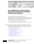
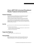
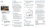
For each sector, the components of a multipoint headend system (see Figure 1) consist of the necessary
cables and:
Figure 1
•
One Cisco uBR7200 series universal broadband router
•
One wireless modem card installed in the router
•
One power feed panel
•
One or two antennas (second antenna for diversity reception is optional)
•
One or two wireless transverters containing the RF amplifier (one for each antenna)
•
One or two duplexers (one for each wireless transverter)
Components of the Multipoint Headend System (transverter hail shield not shown)
Duplexer
PWR
ON
ON
OFF
2
ON
3
OFF
PWR
ON
PWR
ON
ON
CISCO uBR – WMF4A
4
3
2
1
1
OFF
4
ON
POWER FEED PANEL
OFF
PWR
ON
MCW 4
MCW 3
MCW 2
MCW 1
Point-to-multipoint
power feed panel
Cisco uBR7200
series router
uBR-MCW-MDA
E
E
A
DAT
IV
CE
RE
Wireless
point-to-multipoint
transverter
Cisco IOS Release 12.1(5)XM
2
10MHz
IN
PFP
MONITOR
DIVERSITY
ND
SE
IC
RV
A
DAT
R
IE
RR
CA
T
OU
OF
SE
OR
MIN
RM
RM
ALA
R
JO
MA
ALA
D
LE
AB
EN
PFP
MONITOR
MAIN
Point-to-multipoint
head-end
wireless modem card
35167
10MHz
OUT
Multipoint Wireless Support for the Cisco uBR7200 Series Universal Broadband Router
Feature Overview
Multipoint Headend Components
Router
The Cisco uBR7200 series are designed for two-way transmission of digital data using either coaxial
cable or broadband fixed wireless signals. These routers support IP routing with a wide variety of
protocols and any combination of Ethernet, Fast Ethernet, High-Speed Serial Interface (HSSI), serial,
and Asynchronous Transfer Mode (ATM) media. Network interfaces reside on port adapters that
provide the connection between the router and external networks. Cable or wireless interfaces reside on
modem cards and provide the connection to cable or wireless networks.
Other features include:
•
Online insertion and removal (OIR)—Add, replace, or remove a port adapter and modem cards
without interrupting the system or entering any console commands
•
Downloadable software—Load new images into Flash memory remotely, without having to
physically access the router
For further information regarding the Cisco uBR7200 series, including detailed installation and
configuration instructions, refer to the Cisco uBR7200 Series Universal Broadband Router Installation
and Configuration Guide.
Wireless Modem Card
The wireless modem card installs in a modem card slot of a Cisco uBR7200 series. It is configured
through the router’s system console or via the CiscoView network management system. The wireless
modem card provides the control and data interface to the system’s digital motherboard and the radio
frequency (RF) subsystem in the wireless transverter. It also provides the up/down conversion from
baseband to intermediate frequency (IF).
The wireless modem card consists of the following components:
•
Digital motherboard
•
IF analog board
•
10-MHz input connection for external reference clock signal (external reference clock is optional)
•
10-MHz output connection for forwarding optional external reference clock signal to another
wireless modem card
•
Monitor connections for monitoring the power feed panel connections (main and diversity)
•
Power feed panel connections (main and diversity)
•
Light-emitting diodes (LEDs) that provide a visual indication of the state of the modem card
For further information regarding the wireless modem card, including detailed installation and
configuration information, refer to the Cisco uBR7200 Series Router Multipoint Wireless Modem Card
and Subsystem Installation document.
Power Feed Panel
The power feed panel serves as an interconnection device between the wireless modem card, the
wireless transverter, and a –48 VDC power supply. The main purpose of this unit is to provide
DC power to the system, provide control signals to the wireless transverter, and transmit and receive IF
signals to and from the transverters. In addition, the unit contains circuit breakers for the DC power.
Cisco IOS Release 12.1(5)XM
3
Multipoint Wireless Support for the Cisco uBR7200 Series Universal Broadband Router
Feature Overview
The power feed panel consists of the following components:
•
Coaxial cable connection ports to the wireless modem card on the front panel
•
Power ON/OFF switches on the front panel, with LED power indicators
•
Coaxial cable connection ports to the wireless transverter on the rear panel, with LED power
indicators
•
DC power supply terminal blocks on the rear panel
At least one power feed panel is required for each installation. Each power feed panel supports a
maximum of four wireless transverters.
For further information regarding the power feed panel, including detailed installation information,
refer to the Cisco uBR7200 Series Router Multipoint Wireless Modem Card and Subsystem Installation
document.
Wireless Transverter
The ruggedized wireless transverter is the outdoor data interface to the indoor subsystems. It provides
up/down conversion from IF to RF frequencies.
The wireless transverter consists of the following components:
•
RF head
•
Connector port for IF input, power, and control signal
•
Duplexer assembly with antenna connection
For further information regarding the wireless transverter, including detailed installation information,
refer to the Cisco uBR7200 Series Router Multipoint Wireless Modem Card and Subsystem Installation
document.
Benefits
The broadband fixed wireless multipoint system provides:
•
Fast, easy deployment
•
Flexibility—Various interfaces to the host routers and numerous network deployment plans
•
End-to-end Cisco IOS network, enabling multiservice security, multimedia, and management
support
•
Scalable network growth through the addition of more cells or sectors
•
Full-duplex data rates of up to 22 Mbps
•
Non-line-of-sight (Non-LOS) Vector Orthogonal Frequency Division Multiplexing (VOFDM)
technology, enabling greater service coverage
Related Features and Technologies
The point-to-point wireless router system.
Cisco IOS Release 12.1(5)XM
4
Multipoint Wireless Support for the Cisco uBR7200 Series Universal Broadband Router
Supported Platforms
Related Documents
Headend documents:
•
Cisco uBR7200 Series Multipoint Wireless Modem Card & Subsystem Installation
•
Cisco Multipoint Headend Wireless Transverter Duplexer Replacement Instructions
•
Cisco Multipoint Headend Power Feed Panel Replacement Instructions
•
Cisco Multipoint Headend Wireless Transverter Replacement Instructions
•
Cisco Wireless Transverter Hail Shield Installation Instructions
Subscriber-unit documents:
•
Multipoint Wireless Support for the Cisco 2600 and 3600 Series Routers
•
Cisco 2600 Series Hardware Installation Guide
•
Software Configuration Guide (for Cisco 3600 series and Cisco 2600 series routers)
•
Cisco Network Modules Hardware Installation Guide (for Cisco 3600 series and Cisco 2600 series
routers)
Supported Platforms
uBR7200 series
Supported Standards, MIBs, and RFCs
Standards
DOCSIS 1.0 and 1.0+. The DOCSIS 1.0+ implementation is DOCSIS 1.0 with quality-of-service (QoS)
support.
MIBs
This feature is supported by Cisco uBR7200 series MIBs and DOCSIS MIBs enhancing the
manageability of customer infrastructures.
To obtain lists of MIBs supported by platform and Cisco IOS release and to download MIB modules, go to
the Cisco MIB web site on Cisco Connection Online (CCO) at
http://www.cisco.com/public/sw-center/netmgmt/cmtk/mibs.shtml.
RFCs
No new or modified RFCs are supported by this feature.
Prerequisites
Multipoint wireless support
Cisco IOS Release 12.1(5)XM
5
Multipoint Wireless Support for the Cisco uBR7200 Series Universal Broadband Router
Configuration Tasks
Configuration Tasks
This section discusses the following configuration tasks for the multipoint fixed wireless feature:
•
Multipoint CLI Commands Classification
•
Overriding the Default Microcode Path
•
Configuring IF Loopback (Optional)
•
Configuring RF Loopback (Optional)
•
Setting the Power Levels and Frequencies
•
Configuring the Automatic Level Control (ALC)
•
Configuring the Modulation Profile for a Wireless Link
Multipoint CLI Commands Classification
The multipoint headend system CLI commands are classified as follows. Click on the link to go to the
list of commands under each class.
Note
•
Startup Commands
•
Installation and Configuration Commands
•
Verification Commands
•
Operating Commands
•
Monitoring Commands
•
Troubleshooting Commands
This classification is made to help the user in chunking the commands. Some of the
commands can be listed under any of these groups.
Cisco IOS Release 12.1(5)XM
6
Multipoint Wireless Support for the Cisco uBR7200 Series Universal Broadband Router
Configuration Tasks
Overriding the Default Microcode Path
The wireless line card requires external microcode images in order to operate. The Cisco IOS software has
a default file path where it looks to find the microcode and the microcode version. For routers that are
configured with line cards at the factory, the path and version of the microcode image in flash memory
matches the default setting and allows the line card to come up without any additional configuration.
However, you may want to override the default microcode path, for example, to upgrade your software to
the latest release. Use the following steps to change the path for the microcode.
Command
Purpose
Step 1
Router# dir flash
Displays the content of the Flash memory.
Step 2
Router# show microcode
Displays the default path for the microcode.
Step 3
Router# config t
Enters the global configuration mode.
Step 4
Router(config)# microcode cwrhe bundle-path
Specifies the a new path for the headend
microcode bundle.
Step 5
Router(config)# end
Exits the global configuration mode and enters the
EXEC mode.
Step 6
Router# show microcode
Displays the specified path for the microcode.
Step 7
Router# microcode reload cwrhe
Loads the microcode onto the line card.
Step 8
Router# copy running-config startup-config
Saves the path for the microcode so that the
microcode is loaded from the new path the next
time the router is rebooted.
Configuring IF Loopback (Optional)
An IF loopback confirms that the hardware is seated properly in the chassis and that the analog and signal
processing portions of the wireless modem card are functioning as expected. Loopback does not test
forward error corrections (FEC) and MAC-layer interface of the line card; other tests must be done for these
portions of the line card. Each receive path must be tested individually when there are two antennas
employed.
Use the following commands to execute an IF loopback. Specifying these commands shuts down the
radio link and initiates the IF loopback.
Command
Purpose
Step 1
Router(config-if)# shut
Stops the interface.
Step 2
Router(config-if)# loopback local if main 2
Configures the IF to loop the lower half of the
channel.
Step 3
Router(config-if)# no shut
Brings up the loopback mode.
Step 4
Router(config-if)# shut
Stops the interface.
Step 5
Router(config-if)# loopback local if main 3
Configures the IF to loop the upper half of the
channel.
Step 6
Router(config-if)# no shut
Brings up the loopback mode.
Step 7
Router(config-if)# shut
Stops the interface.
Cisco IOS Release 12.1(5)XM
7
Multipoint Wireless Support for the Cisco uBR7200 Series Universal Broadband Router
Configuration Tasks
Command
Purpose
Step 8
Router(config-if)# no loopback
Removes the loopback commands used up to this
point.
Step 9
Router(config-if)# no shut
Establishes link.
If a second antenna is employed, its receive path must also be tested. Use the following commands to
configure the second antenna. Issue the show running-configuration command to see the IF
configuration.
Command
Purpose
Step 1
Router(config-if)# shut
Stops the interface.
Step 2
Router(config-if)# loopback local if diversity 2
Configures the IF to loop the lower half of the
channel for antenna 2.
Step 3
Router(config-if)# no shut
Brings up the loopback mode.
Step 4
Router(config-if)# shut
Stops the interface.
Step 5
Router(config-if)# loopback local if diversity 3
Configures the IF to loop the upper half of the
channel for antenna 2.
Step 6
Router(config-if)# no shut
Brings up the loopback mode.
Step 7
Router(config-if)# shut
Stops the interface.
Step 8
Router(config-if)# no loopback
Removes the loopback commands used up to this
point.
Step 9
Router(config-if)# no shut
Establishes link.
Configuring RF Loopback (Optional)
An RF loopback confirms that the wiring to the transverter is correct, that communication has been
established from the line card to the transverter, and that the transverter is operating correctly. (It does not
test the duplexer, which is the final stage before the signal is sent to the antenna.) Also, loopback does not
test forward error corrections (FEC) and MAC-layer interface of the line card; other tests must be done for
these portions of the line card. Because there is only one transmit path, the path to each transverter must be
tested separately. Use the following commands to configure the RF loopback.
Command
Purpose
Step 1
Router(config-if)# shut
Stops the interface.
Step 2
Router(config-if)# loopback local rf main 2
Configures the RF to loop the lower half of the
channel.
Step 3
Router(config-if)# no shut
Brings up the loopback mode.
Step 4
Router(config-if)# shut
Stops the interface.
Step 5
Router(config-if)# loopback local rf main 3
Configures the RF to loop the upper half of the
channel.
Step 6
Router(config-if)# no shut
Brings up the loopback mode.
Step 7
Router(config-if)# shut
Stops the interface.
Cisco IOS Release 12.1(5)XM
8
Multipoint Wireless Support for the Cisco uBR7200 Series Universal Broadband Router
Configuration Tasks
Command
Purpose
Step 8
Router(config-if)# loopback local rf diversity 2
Configures the RF to loop the lower half of the
channel for antenna 2. Note that this command is
issued only if a second antenna is used.
Step 9
Router(config-if)# loopback local rf diversity 3
Configures the RF to loop the upper half of the
channel for antenna 2. Note that this command is
issued only if a second antenna is used.
Step 10
Router(config-if)# no shut
Brings up in loopback mode.
Step 11
Router(config-if)# shut
Stops the interface.
Step 12
Router(config-if)# no loopback
Removes any loopback commands used up to this
point.
Step 13
Router(config-if)# no shut
Establishes link.
Issue the show running-configuration command to see the RF configuration.
Configuring the Modulation Profile for a Wireless Link
The modulation profile describes the physical layer configuration of a wireless channel. The correct settings
to use are the result of extensive site planning and quality-of-service models. The specified settings are
stored in the router as profiles. These profile settings are entered in the router only once, but can be applied
to multiple line cards in the router.
Command
Purpose
Step 1
Router# show radio capability modulation-profile int
radio slot/port
Displays the modulation profiles supported by the
radio card installed in a particular slot/port.
Step 2
Router# configure terminal
Enables the global interface configuration mode.
Step 3
Router(config)# radio modulation-profile p bandwidth
width throughput x.y mulipath-robust high burst-length
medium
Creates a modulation profile.
Step 4
Router(config)# end
Exits the interface configuration mode and enters
the EXEC mode.
Step 5
Router# show radio modulation-profile
Displays the modulation-profile configuration
settings that the user specified.
Step 6
Router# configure terminal
Enables the global interface configuration mode.
Step 7
Router(config)# interface radio slot/port
Enters radio interface configuration mode.
Step 8
Router(config-if)# radio upstream usport subchannel sn
modulation-profile p
Applies the modulation profile to an upstream
port.
Cisco IOS Release 12.1(5)XM
9
Multipoint Wireless Support for the Cisco uBR7200 Series Universal Broadband Router
Configuration Tasks
Setting the Power Levels and Frequencies
The power levels must be set correctly to ensure correct operation and compliance with the governing
regulatory bodies (such as the FCC). After the power settings have been determined, use the following
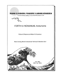
commands to configure the router.Refer to the following subchannel map as a reference for the
subchannel assignments:
one "channel"
1
4
3
5
6
7
35543
2
Downstream Channel
Command
Purpose
Step 1
Router(config-if)# radio transmit-power power-level
Sets the upstream transmit-power to power in
dBm.
Step 2
Router(config-if)# radio downstream frequency freq
width width
Sets frequency and bandwidth for the downstream
channel.
Step 3
Router(config-if)# radio downstream subchannel sc
modulation-profile p
Sets the subchannel and modulation-profile
assignment for the downstream channel.
Note
Cisco IOS Release 12.1(5)XM
10
This command specifies the center
frequency and width of the basic hardware
channel. The downstream channel itself
can be full, one-half, or one-quarter of this
bandwidth. For example, the only basic
channel bandwidth that is supported by
the initial hardware release is 6.0 MHz.
Multipoint Wireless Support for the Cisco uBR7200 Series Universal Broadband Router
Configuration Tasks
Upstream Channel
Step 1
Command
Purpose
Router(config)# radio upstream frequency freq width
width
Sets the upstream frequency and bandwidth.
Note
Step 2
Router(config-if)# radio upstream usportnum subchannel
sn modulation-profile p
The width parameter specifies the
bandwith for the upstream channel group
(the basic hardware channel). The freq
parameter specifies the center frequency
for this group of upstream channels. For
example, the only basic channel width that
is supported by the initial hardware
release is 6.0 MHz.
Sets the subchannel and modulation-profile
assignment for the upstream channel.
Note
The bandwidth of the subchannel must
match the bandwidth of the
modulation-profile.
Step 3
Router(config)# radio transmit-power power-level
Sets the downstream transmit power to power in
dBm.
Step 4
Router(config-if)# radio upstream usportnum
target-receive-power power-level
Sets the target receive power in dBm for the
upstream port. The usportnum field specifies the
upstream port number. The target receive power
must be set for each upstream port.
Step 5
Router(config-if)# radio upstream usportnum shutdown
Shuts down the upstream channel.
Configuring the Automatic Level Control (ALC)
The automatic level control (ALC) module governs the individual transmit power levels of all the
subscriber units. The purpose of ALC is to ensure that the target receive power at the headend is maintained
over time by taking power measurements of all the subscribers many times per second. Taking power
measurements in small intervals results in better resilience to the fading environment, but it consumes more
upstream bandwidth. ALC can be disabled, but this is not recommended because it results in poor upstream
link performance. The current system allows only one interval setting for an entire sector. The default
interval is 96 ms.
Command
Purpose
Step 1
Router# configure terminal
Enables the global interface configuration mode.
Step 2
Router(config)# interface radio slot/port
Specifies the line card to be configured. In this
example, the line card installed in a specific
slot/port number.
Step 3
Router(config-if)# radio alc interval interval
Configures the ALC interval for the sector at a
specified interval value.
Cisco IOS Release 12.1(5)XM
11
Multipoint Wireless Support for the Cisco uBR7200 Series Universal Broadband Router
Monitoring and Maintaining Multipoint Wireless Configurations
Command
Purpose
Step 4
Router(config-if)# end
Exits the interface configuration mode and get to
the EXEC mode.
Step 5
Router# show interface radio slot/port alc
Displays the ALC setting that you specified.
Verifying the Wireless Modem Card Configuration
Step 1
Enter the show running-configuration command in privileged EXEC mode to display the
configuration currently in effect on the Cisco uBR7200 series.
Step 2
Enter the show startup-configuration command in privileged EXEC mode to display the system
startup configuration.
For a complete list of commands to verify the installation and configuration of your fixed wireless
multipoint system, see the “Verification Commands”section.
Monitoring and Maintaining Multipoint Wireless
Configurations
This section describes the clear and show commands that are used to monitor and maintain the
multipoint fixed wireless system. For a complete list of commands to monitor and maintain your fixed
wireless multipoint system, see “Monitoring Commands” under the command reference section. For the
syntax and description of a command, refer to the “Command Reference” section of this document.
Command
Purpose
Router# clear radio flap-list
Clears the current radio flap-list entries for a
specific subscriber unit or for all subscriber units.
Router# clear radio link-metrics
Clears the link metrics settings.
Router# clear radio subscriber counters
Clears the counters for a radio modem or all radio
modems in the Station Maintenance List.
Router# clear radio subscriber reset
Resets the radio modem or all radio modems on the
network.
Router# show controllers radio downstream
Displays downstream port information for a
wireless modem card.
Router# show controllers radio if
Displays the IF hardware information for the
specified radio interface.
Router# show controllers radio rf
Displays the RF hardware information for the
specified radio interface.
Router# show controllers radio upstream
Displays upstream port information for a wireless
modem card.
Router# show interfaces radio metrics
Displays the parameters measured during the
operation of the radio link.
Router# show interface radio accounting
Displays radio accounting information for a
wireless modem card.
Cisco IOS Release 12.1(5)XM
12
Multipoint Wireless Support for the Cisco uBR7200 Series Universal Broadband Router
Monitoring and Maintaining Multipoint Wireless Configurations
Command
Purpose
Router# show interface radio alc
Displays the automatic level control (ALC) and
power ranging configuration information for the
downstream.
Router# show interface radio downstream
Displays downstream port information for a
wireless modem card.
Router# show interface radio hist-data
Displays histogram data.
Router# show interface radio hist-spec
Displays histogram specifications.
Router# show interface radio led
Displays the status of light-emitting diodes (LEDs)
on the wireless modem card and the events related
to the major and minor LEDs.
Router# show interface radio ranging
Displays ranging information.
Router# show interface radio rf-meas-interval
Displays the intervals of the ambient noise and the
calibration noise measurements of the radio card
for the specified slot and downstream port
numbers.
Router# show interface radio sid
Displays information by service identifier (SID)
about each subscriber unit on the network.
Router# show interface radio snap-data
Displays the data captured for the snapshot
specification.
Router# show interface radio snap-spec
Displays the configured snapshot information.
Router# show interface radio thresholds
Displays the set of currently configured thresholds
on the radio modem card.
Router# show interface radio tl-data
Displays the timelines data collected for the
identified specifications.
Router# show interface radio tl-spec
Displays the details of the currently configured
timeline specifications.
Router# show interface radio upstream
Displays upstream port information for a wireless
modem card.
Router# show interface radio zero-burst
Displays zero-burst information for the
downstream port of a wireless modem card.
Router# show radio device
Displays the access group information for the
subscriber unit or the host behind the subscriber
unit.
Router# show radio errors
Displays error details for the radio interface.
Router# show radio flap-list
Displays the radio flap-list of a wireless modem
card.
Router# show radio capability modulation-profile
Displays the modulation profiles supported by the
radio linecard.
Router# show radio modulation-profile
Displays modulation profile information for a
wireless modem card that the user specified.
Router# show radio privacy kek
Displays the key encryption life-time and
grace-time values that have been set.
Cisco IOS Release 12.1(5)XM
13
Multipoint Wireless Support for the Cisco uBR7200 Series Universal Broadband Router
Monitoring and Maintaining Multipoint Wireless Configurations
Command
Purpose
Router# show radio privacy tek
Displays the traffic encryption life-time and
grace-time values that have been set.
Router# show radio qos profile
Displays quality-of-service (QoS) profile and the
configuration information for the profile.
Router# show radio subscriber
Displays information about a wireless modem card
that is on the network.
Cisco IOS Release 12.1(5)XM
14
Multipoint Wireless Support for the Cisco uBR7200 Series Universal Broadband Router
Configuration Examples
Configuration Examples
This section provides the following examples for configuring the multipoint headend wireless modem
car:
•
RF-RF Link Configuration
•
Downstream Channel Configuration
•
Upstream Channel Configuration
•
Modulation Profiles Configurations
RF-RF Link Configuration
The following is an example of RF-RF link configuration:
interface Radio3/0 multipoint
ip address 7.7.7.1 255.255.255.0
radio cable-loss auto
radio transmit-power 34
radio upstream frequency 2503000 width 6.0
radio upstream 0 subchannel 2 modulation-profile 8
no radio upstream 0 shutdown
radio upstream 1 shutdown
radio upstream 2 shutdown
radio upstream 3 shutdown
radio downstream frequency 2545000 width 6.0
radio downstream subchannel 2 modulation-profile 1
Downstream Channel Configuration
The following is an example of downstream channel configuration:
radio transmit-power 31
radio downstream frequency 2653000 width 6.0
radio downstream subchannel 4 modulation-profile 10
Upstream Channel Configuration
The following is an example of upstream channel configuration:
radio upstream frequency 2587000 width 6.0
radio upstream 0 subchannel 4 modulation-profile
radio upstream 0 target-receive-power -72
no radio upstream 0 shutdown
radio upstream 1 subchannel 5 modulation-profile
radio upstream 1 target-receive-power -72
no radio upstream 1 shutdown
radio upstream 2 subchannel 6 modulation-profile
radio upstream 2 target-receive-power -72
no radio upstream 2 shutdown
radio upstream 3 subchannel 7 modulation-profile
radio upstream 3 target-receive-power -72
no radio upstream 3 shutdown
14
14
14
14
Cisco IOS Release 12.1(5)XM
15
Multipoint Wireless Support for the Cisco uBR7200 Series Universal Broadband Router
Configuration Examples
Splitting an upstream channel
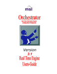
The following steps show how to split an upstream channel into two smaller upstream channels. In this
example, a 3-MHz upstream (upstream 0, subchannel 2) is split into two 1.5-MHz upstreams, using the
following commands. Refer to the following subchannel map as a reference for the subchannel
assignments:
one "channel"
1
4
3
5
6
7
35543
2
Command
Purpose
Router(config-if)# no radio upstream 0 subchannel
Removes the subchannel assignment from
upstream port 0.
Router(config-if)# radio upstream 0 subchannel 4
modulation-profile 7
Assigns upstream port 0 to subchannel 4 using
modulation profile 7, which must be a 1.5-MHz
modulation profile.
Router(config-if)# radio upstream 1 subchannel 5
modulation-profile 7
Assigns upstream 1 to subchannel 5, using
modulation profile 7.
Router(config-if)# no radio upstream 0 shutdown
Enables upstream 0.
Router(config-if)# no radio upstream 1 shutdown
Enables upstream 1.
Modulation Profiles Configurations
The following are examples of modulation profiles:
radio modulation-profile 1 bandwidth 3.0 throughput 6.6 multipath-robustness high
burst-length medium
radio modulation-profile 2 bandwidth 3.0 throughput 8.6 multipath-robustness high
burst-length medium
radio modulation-profile 3 bandwidth 3.0 throughput 4.4 multipath-robustness high
burst-length medium
Cisco IOS Release 12.1(5)XM
16
Multipoint Wireless Support for the Cisco uBR7200 Series Universal Broadband Router
Command Reference
Command Reference
This section documents the new commands associated with the fixed wireless multipoint feature. All
other commands used with this feature are documented in the Cisco IOS Release 12.1 command
reference publications. The commands are classified into the following groups:
Note
•
Startup Commands
•
Installation and Configuration Commands
•
Verification Commands
•
Operating Commands
•
Monitoring Commands
•
Troubleshooting Commands
This classification is created to help the user in chunking the commands. Some of the
commands can be listed under any of these groups.
Startup Commands
Use the following commands to startup your fixed wireless multipoint headend system. Note that these
commands are not specific to this feature; they are Cisco IOS generic commands, and their syntax can
be found in the command reference documentation for Cisco IOS Release 12.1, available on CCO and
the Documentation CD-ROM.
•
show running-configuration
•
show start-up configuration
•
shut
•
write
Installation and Configuration Commands
Use the following commands to install and configure your fixed wireless multipoint headend system:
•
loopback
•
microcode reload
•
radio arp
•
radio cable-loss
•
radio downstream annex B
•
radio downstream frequency
•
radio downstream subchannel modulation-profile
•
radio helper-address
•
radio insertion-interval
•
radio interface radio rf-update duplexer
•
radio modulation-profile
•
radio receive-antennas
Cisco IOS Release 12.1(5)XM
17
Multipoint Wireless Support for the Cisco uBR7200 Series Universal Broadband Router
Command Reference
•
radio self-test
•
radio source-verify
•
radio transmit-power
•
radio upstream data-backoff
•
radio upstream description
•
radio upstream frequency
•
radio upstream range-backoff
•
radio upstream shutdown
•
radio upstream subchannel
•
radio upstream target-receive-power
Verification Commands
Use the following commands to verify your installation and configuration of the fixed wireless
multipoint headend system:
•
show controllers radio downstream
•
show controllers radio if
•
show controllers radio rf
•
show controllers radio upstream
•
show interface radio alc
•
show interface radio downstream
•
show interface radio ranging
•
show interface radio upstream
•
show radio capability modulation-profile
•
show radio modulation-profile
Operating Commands
After you have installed, configured, and verified your fixed wireless multipoint headend system, use
the following commands to operate your system:
•
clear radio flap-list
•
clear radio link-metrics
•
clear radio subscriber counters
•
clear radio subscriber reset
•
pppoe enable
•
pppoe-forwarding
•
pppoe forwarding default-qos-level
•
pppoe forwarding group
•
pppoe su-mac
•
pppoe tag
Cisco IOS Release 12.1(5)XM
18
Multipoint Wireless Support for the Cisco uBR7200 Series Universal Broadband Router
Command Reference
•
radio alc
•
radio downstream rate-limit
•
radio ip-broadcast-echo
•
radio ip-multicast-echo
•
radio privacy kek grace-time
•
radio privacy kek life-time
•
radio privacy mandatory
•
radio privacy tek grace-time
•
radio privacy tek life-time
•
radio proxy-arp
•
radio qos permission
•
radio qos profile
•
radio ra-backoff
•
radio relay-agent-option
•
radio rf-meas-interval ambient
•
radio rf-meas-interval calibration
•
radio shared-secret
•
radio upstream admission-control
•
radio upstream rate-limit
•
show interface radio rf-meas-interval
•
show interface radio zero-burst
•
show radio privacy kek
•
show radio privacy tek
•
show radio qos profile
Monitoring Commands
Use the following commands to monitor and maintain your fixed wireless multipoint headend system:
•
radio flap-list aging
•
radio flap-list insertion-time
•
radio flap-list miss-threshold
•
radio flap-list size
•
radio metrics-threshold-channel
•
radio metrics-threshold-su
•
radio threshold
•
show interfaces radio metrics
•
show interface radio accounting
•
show interface radio led
Cisco IOS Release 12.1(5)XM
19
Multipoint Wireless Support for the Cisco uBR7200 Series Universal Broadband Router
Command Reference
•
show interface radio sid
•
show interface radio thresholds
•
show radio device
•
show radio errors
•
show radio flap-list
•
show radio subscriber
Troubleshooting Commands
Use the following commands to troubleshoot your fixed wireless multipoint headend system:
•
ping docsis
•
radio hist-display
•
radio histogram
•
radio interface radio hist-clear
•
radio interface radio hist-start
•
radio interface radio hist-stop
•
radio interface radio tl-clear
•
radio interface radio tl-start
•
radio interface radio tl-stop
•
radio snapshot
•
radio timeline
•
show controllers radio
•
show interface radio hist-data
•
show interface radio hist-spec
•
show interface radio snap-data
•
show interface radio snap-spec
•
show interface radio tl-data
•
show interface radio tl-spec
Cisco IOS Release 12.1(5)XM
20
Multipoint Wireless Support for the Cisco uBR7200 Series Universal Broadband Router
clear radio flap-list
clear radio flap-list
To clear the current radio flap list entries for a specific subscriber unit or for all subscriber units, use
the clear radio flap-list EXEC command.
clear radio flap-list [MAC-address | all]
Syntax Description
MAC-address
Specifies the MAC address to clear the flap-list entries for a specific
wireless modem card.
all
Clears the entries for all the wireless modems in the flap-list.
Defaults
No default behavior or values.
Command Modes
EXEC
Command History
Release
Modification
12.1(3)XQ1
This command was introduced.
Usage Guidelines
Examples
When using this command, make sure that:
•
You are in global configuration mode when you enter this command.
•
You have recorded and analyzed all of the flapping activity on the radio modem before you clear
the flap list.
The following example shows how to clear the entries in the radio flap list for the subscriber unit with
a specific MAC address:
CMTS01(config)# clear radio flap-list 0010.7b6b.5d1d
Related Commands
Command
Description
radio flap-list aging
Specifies the number of days to record and retain flapping activity on a radio
subscriber unit in the flap list table.
radio flap-list
insertion-time
Sets the radio flap-list insertion time.
radio flap-list
miss-threshold
Sets the miss-threshold for recording a flap-list event.
radio flap-list size
Specifies the maximum number of radio subscriber units to be reported in
the radio flap-list table.
show radio flap-list
Displays the radio flap-list of a wireless modem card.
Cisco IOS Release 12.1(5)XM
21
Multipoint Wireless Support for the Cisco uBR7200 Series Universal Broadband Router
clear radio link-metrics
clear radio link-metrics
To clear link metrics settings, use the clear radio link-metrics EXEC command.
clear radio slot/port link-metrics
Syntax Description
slot/port
Defaults
No default behavior or values.
Command Modes
EXEC
Command History
Release
Modification
12.1(3)XQ1
This command was introduced.
The slot and port address.
Usage Guidelines
Make sure that you record and analyze the link-metrics data before executing this command.
Examples
The following example shows how to clear all radio link-metrics details:
Router# clear radio 6/0 link-metrics
Related Commands
Command
Description
show interfaces radio
metrics
Displays the parameters measured during the operation of the radio link.
show interface radio
metrics-threshold
Displays the current link-metrics configuration thresholds for a radio
modem.
Cisco IOS Release 12.1(5)XM
22
Multipoint Wireless Support for the Cisco uBR7200 Series Universal Broadband Router
clear radio subscriber counters
clear radio subscriber counters
To clear the counters for a radio modem or all radio modems in the Station Maintenance List, use the
clear radio subscriber counters EXEC command.
clear radio subscriber [address | all] counters
Syntax Description
address
Clears the counters in the Station Maintenance List for the subscriber unit
with a specific IP address or MAC address.
all
Clears the counters in the Station Maintenace List for all subscriber units.
Defaults
No default behavior or values.
Command Modes
EXEC
Command History
Release
Modification
12.1(3)XQ1
This command was introduced.
Usage Guidelines
Make sure that you record and analyze the data before executing this command.
Examples
The following example shows how to clear the flapping counters for all the subscribers that are on the
network:
Router# clear radio subscriber all counter
Related Commands
Command
Description
clear radio subscriber Removes subscribers from the Station Maintenance List.
reset
show radio subscriber Displays information about a wireless modem card that is on the network.
Cisco IOS Release 12.1(5)XM
23
Multipoint Wireless Support for the Cisco uBR7200 Series Universal Broadband Router
clear radio subscriber reset
clear radio subscriber reset
To remove a radio modem or all radio modems from the Station Maintenance List and reset the radio
modem or all radio modems on the network, use the clear radio subscriber reset EXEC command.
clear radio [address | all]
Syntax Description
address
Removes the subscriber unit with a specific IP or MAC address from the
Station Maintenance List.
all
Removes all subscriber units from the Station Maintenance List.
Defaults
No default behavior or values.
Command Modes
EXEC
Command History
Release
Modification
12.1(3)XQ1
This command was introduced.
Usage Guidelines
Make sure that you record and analyze the data before you execute this command.
Examples
The following example shows how to remove all the subscribers from the Station Maintenance List:
Router# clear radio subscriber all reset
Related Commands
Command
Description
clear radio subscriber Clears flapping counters for the subscribers.
counter
Cisco IOS Release 12.1(5)XM
24
Multipoint Wireless Support for the Cisco uBR7200 Series Universal Broadband Router
loopback
loopback
To place the specified module in loopback mode, use the loopback interface configuration command.
To remove the loopback specification use the no form of this command.
loopback local [module] [main | diversity] subchannel
no loopback [local module]
Syntax Description
local
(Optional) Specifies that the module is local.
module
Specifies the type of module:
{fir | if | rf}
main | diversity
Specifies the main or the diversity (backup) antenna.
subchannel
[2 | 3] Specifies the subchannel numbers.
Defaults
no loopback
Command Modes
Interface configuration
Command History
Release
Modification
12.1(3)XQ1
This command was introduced.
Usage Guidelines
If you perform a loopback of the RF module while the transverter is attached to an antenna, some
transmit power is radiated. Therefore, it is extremely important that you set the transmit frequency to
your assigned and licensed band frequency. If the transverter is not attached to an antenna, attach an RF
termination device to the duplexer port.
Examples
The following example shows how to initiate a local RF loopback on the main antenna with the lower
half of the subchannel:
Router(config-if)# loopback local rf main 2
Related Commands
Command
Description
show
Displays loopback configuration settings.
running-configuration
Cisco IOS Release 12.1(5)XM
25
Multipoint Wireless Support for the Cisco uBR7200 Series Universal Broadband Router
microcode reload
microcode reload
To configure the system to load its microcode from the specified slot number, use the microcode reload
privileged EXEC command.
microcode reload {all | cwrhe [slot slot]}
Syntax Description
all
Specifies to reload all hardware types that support downloadable
microcode.
cwrhe
Specifies to reload the microcode for the wireless headend port adapter.
slot slot
Specifies the slot number where to reload the microcode. Valid values are 0
to 6.
Defaults
No default behaviors or values.
Command Modes
Privileged EXEC
Command History
Release
Modification
12.1(3)XQ1
This command was introduced.
Usage Guidelines
The microcode command is not normally needed when using the factory installed images.
Examples
The following example shows how to reload a microcode in slot 6:
Router# microcode reload cwrhe slot 6
Cisco IOS Release 12.1(5)XM
26
Multipoint Wireless Support for the Cisco uBR7200 Series Universal Broadband Router
ping docsis
ping docsis
To determine whether a subscriber unit is on the network, use the ping docsis privileged EXEC
command. To disable this function, use the no form of this command.
ping docsis [MAC-address | ip-address]
no ping docsis
Syntax Description
MAC-address
Specifies radio modem MAC address.
ip-address
Specifies radio modem IP address.
Defaults
No default behavior or values.
Command Modes
Privileged EXEC
Command History
Release
Modification
12.1(3)XQ1
This command was introduced.
Usage Guidelines
Make sure that you are using a valid MAC or IP address for the radio modem that you want to ping.
Examples
The following example shows how to verify if a subscriber unit is on the network:
Router# ping docsis 172.19.0.0
Cisco IOS Release 12.1(5)XM
27
Multipoint Wireless Support for the Cisco uBR7200 Series Universal Broadband Router
pppoe enable
pppoe enable
To enable Point-to-Point Protocol over Ethernet (PPPoE) termination on the radio interface, use the
pppoe enable interface configuration command. To disable, use the no form of this command.
pppoe enable
no pppoe enable
Syntax Description
This command has no arguments or keywords.
Defaults
By default PPPoE is disabled.
Command Modes
Interface configuration
Command History
Release
Modification
12.1(3)XQ1
This command was introduced on the fixed wireless multipoint product.
Usage Guidelines
The pppoe enable command and the pppoe-forwarding command cannot be configured at the same
time. You can configure only one or the other at any given time.
Examples
The following example shows how to enable PPPoE on the radio interface:
Router(config-if)# pppoe enable
Related Commands
Command
Description
pppoe-forwarding
Enables PPPoE forwarding on the router.
show interface
Displays information about whether or not PPPoE termination or PPPoE
forwarding is enabled.
Cisco IOS Release 12.1(5)XM
28
Multipoint Wireless Support for the Cisco uBR7200 Series Universal Broadband Router
pppoe-forwarding
pppoe-forwarding
To enable PPP over Ethernet forwarding on the router, use the pppoe-forwarding global configuration
command. To disable PPPoE forwarding on the router, use the no form of this command.
pppoe-forwarding
no pppoe-forwarding
Syntax Description
This command has no arguments or keywords.
Defaults
By default PPPoE forwarding is disabled (no pppoe-forwarding).
Command Modes
Global configuration
Command History
Release
Modification
12.1(3)XQ1
This command was introduced.
Usage Guidelines
Examples
The pppoe enable command and the pppoe-forwarding command cannot be configured at the same
time. You can configure only one or the other at any given time.
The following example shows how to set PPPoE forwarding on the radio interface:
Router(config)# pppoe-forwarding
Related Commands
Command
Description
pppoe enable
Enables PPPoE termination on the radio interface.
pppoe-forwarding
Enables PPPoE forwarding on the router.
forwarding
default-qos-level
Sets all packets received on the radio interface with a single
quality-of-service (QoS) level.
forwarding group
Sets a PPPoE forwarding group number on the radio interface.
su-mac
Specifies the subscriber unit MAC address that is mapped from the radio
interface to the virtual circuit (VC) on the ATM interface for PPPoE
forwarding.
tag
Specifies the subscriber unit tag name that is mapped from the radio
interface onto the VC on the ATM interface for PPPoE forwarding.
Cisco IOS Release 12.1(5)XM
29
Multipoint Wireless Support for the Cisco uBR7200 Series Universal Broadband Router
pppoe forwarding default-qos-level
pppoe forwarding default-qos-level
To set all packets received on the radio interface with a single quality-of-service (QoS) level, use the
forwarding default-qos-level radio interface configuration command. To disable PPPoE forwarding,
use the no form of this command.
forwarding default-qos-level qos-level-num
no forwarding default-qos-level qos-level-num
Syntax Description
qos-level-num
Defaults
No default behaviors or values.
Command Modes
Interface configuration
Command History
Release
Modification
12.1(3)XQ1
This command was introduced.
Examples
The following example shows how to set PPPoE forwarding default-qos-level value to 1:
Router(config-if)#
Related Commands
forwarding default-qos-level 1
Command
Description
pppoe-forwarding
Enables PPPoE forwarding on the radio interface.
forwarding group
Sets a PPPoE forwarding group number on the router.
su-mac
Specifies the subscriber unit MAC address that is mapped from the radio
interface to the virtual circuit (VC) on the ATM interface for PPPoE
forwarding.
tag
Specifies the subscriber unit tag name that is mapped from the radio
interface onto the VC on the ATM interface for PPPoE forwarding.
Cisco IOS Release 12.1(5)XM
30
QoS level number to map to a virtual circuit (VC). Valid rage is 1 to
4,294,967,295.
Multipoint Wireless Support for the Cisco uBR7200 Series Universal Broadband Router
pppoe forwarding group
pppoe forwarding group
To set a PPP over Ethernet forwarding group number on the radio interface, use the forwarding group
interface configuration command. To disable forwarding group assignment, use the no form of this
command.
forwarding group group-num
no forwarding group group-num
Syntax Description
group-num
Defaults
No default behaviors or values.
Command Modes
Interface configuration
Command History
Release
Modification
12.1(3)XQ1
This command was introduced.
Specifies PPPoE forwarding group number. Valid range is 1 to 10.
Usage Guidelines
The forwarding group command needs to be set on both the radio interface and the ATM or permanent
virtual circuit (PVC) interface. The forwarding engine maintains an internal table of the forwarding
group. The forwarding group information from the internal table is used for forwarding packets between
the radio interfaces and the ATM or PVC interfaces. The group-num value needs to be the same on both
the radio and the ATM or PVC interfaces. For more information about configuring PPPoE on an ATM
or PVC interface refer to the PPP over Ethernet document.
Examples
The following example shows how to set the PPPoE forwarding group number to 1 for the radio
interface:
Router(config-if)# forwarding group 1
The following example shows how to configure the forwarding group on the ATM or PVC interface:
router(config)# int atm2/0.1 p
router(config-subif)# pvc 0/60
router(config-if-atm-)# forwarding group 1
Cisco IOS Release 12.1(5)XM
31
Multipoint Wireless Support for the Cisco uBR7200 Series Universal Broadband Router
pppoe forwarding group
Related Commands
Command
Description
pppoe-forwarding
Enables PPPoE forwarding on the radio interface.
forwarding
default-qos-level
Sets all packets received on the radio interface with a single
quality-of-service (QoS) level.
su-mac
Specifies the subscriber unit MAC address that is mapped from the radio
interface to the virtual circuit (VC) on the ATM interface for PPPoE
forwarding.
tag
Specifies the subscriber unit tag name that is mapped from the radio
interface onto the VC on the ATM interface for PPPoE forwarding.
Cisco IOS Release 12.1(5)XM
32
Multipoint Wireless Support for the Cisco uBR7200 Series Universal Broadband Router
pppoe su-mac
pppoe su-mac
To to enable PPPoE forwarding on the radio interface using the subscriber unit’s MAC address, use the
su-mac global configuration command. To disable PPPoE specification, use the no form of this
command.
su-mac MAC-address qos-level level-num type {pppoe | all} [cos-id id-num | sid-index]
no su-mac MAC-address qos-level level-num type {pppoe | all} [cos-id id-num | sid-index]
Syntax Description
MAC-address
Specifies the subscriber unit MAC address.
qos-level level-num
Specifies QoS level number to map to a virtual circuit (VC). The range for
level-num is 1 to 1024.
type {pppoe | all}
Specifies packet fowarding options as either pppoe or all.
pppoe
Specifies that only pppoe packets are allowed to forwarding.
all
Specifies that all packets allowed to forwarding.
cos-id id-num
Optional class-of-service identifier specification in TFTP configuration file.
Valid range is 1 to 16.
sid-index
Creates service identifier index in an internal table.
Defaults
No default behaviors or values.
Command Modes
Global configuration
Command History
Release
Modification
12.1(3)XQ1
This command was introduced.
Examples
The following examples show how to associate subscriber unit MAC addresses to QoS-level numbers:
Router(config)# su-mac 0090.8330.0215 qod_level 1 type all cos_id 10
Router(config)# su-mac 0050.7366.1241 qos_level 2 type pppoe cos_id 16
Related Commands
Command
Description
pppoe-forwarding
Enables PPPoE forwarding on the radio interface.
forwarding
default-qos-level
Sets all packets received on the radio interface with a single
quality-of-service (QoS) level.
forwarding group
Sets a PPPoE forwarding group number on the radio interface.
tag
Specifies the subscriber unit tag name that is mapped from the radio
interface onto the VC on the ATM interface for PPPoE forwarding.
Cisco IOS Release 12.1(5)XM
33
Multipoint Wireless Support for the Cisco uBR7200 Series Universal Broadband Router
pppoe tag
pppoe tag
To assign a qos-level tag for packet from a particular SU so that the packet is forwarded to a particular
virtual circuit, use the tag global configuration command. To disable the tag specification, use the no
form of this command.
tag string qos-level level-num type {pppoe | all [sid-index]}
no tag string qos-level level-num type {pppoe | all [sid-index]}
Syntax Description
String
Specifies the tag name to be used.
qos-level level-num
Specifies QoS level number to map to a virtual circuit (VC). The range for
level-num is 1 to 1024.
type {pppoe | all}
Specifies packet fowarding options as either pppoe or all.
pppoe
Specifies that only pppoe packets are allowed to forwarding.
all
Specifies that all packets are allowed to forwarding.
sid-index
Creates service identifier index in an internal table.
Defaults
No default behaviors or values.
Command Modes
Global configuration
Command History
Release
Modification
12.1(3)XQ1
This command was introduced.
Examples
In the following example, all PPPoE packets arriving from an SU previously registered with SU tag
“UunNet-Gold" are assigned qos-level 1:
Router(config)# tag UUNet-Gold qos_level 1 type pppoe
Related Commands
Command
Description
pppoe-forwarding
Enable PPPoE forwarding on the radio interface.
forwarding
default-qos-level
Set all packets received on the radio interface with a single
quality-of-service (QoS)-level.
forwarding group
Sets a PPPoE forwarding group number on the radio interface.
su-mac
Specifies the subscriber unit MAC address that is mapped from the radio
interface to the virtual circuit (VC) on the ATM interface for PPPoE
forwarding.
Cisco IOS Release 12.1(5)XM
34
Multipoint Wireless Support for the Cisco uBR7200 Series Universal Broadband Router
radio alc
radio alc
To enable the automatic level control (ALC) and the power ranging, and to set the ALC attributes at the
headend, use the radio alc interface configuration command. To turn off the ALC and power ranging,
use the no form of this command.
radio alc [interval interval [if-mode standard | robust] [rf-mode very-fast | fast | slow |
very-slow]]
no radio alc
Syntax Description
interval
(Optional) if | rf-mode. If one of the these optional modes is not specified,
the radio interface assumes the values specified prior to ALC and power
ranging being off. Otherwise, the default values of 96 ms, standard, and
fast are used for interval, if-mode, and rf-mode, respectively. Valid range
is 32 ms to 1024 ms, in multiples of 32 ms.
interval
Scheduling interval is the regular interval at which the ALC grant in MAP
is transmitted to the subscriber units. Valid range is 50 to 200 ms.
if-mode
standard | robust (standard is the default).
rf-mode
very-fast | fast | slow | very-slow (fast is the default).
Defaults
The ALC and power ranging are on.
Command Modes
Interface configuration
Command History
Release
Modification
12.1(3)XQ1
This command was introduced.
Usage Guidelines
The radio alc command enables the ALC and power ranging, and sets the scheduling interval of all the
powers for the subscriber IDs of the current radio interface. It also sets the IF and RF modes when the
ALC is on. The scheduling interval is the regular interval at which the ALC enables MAPs to be
transmitted to the subscribers.
Examples
The following example shows how to specify the ALC scheduling interval to 64 ms and set the if-mode
and rf-mode to default values:
Router (config-if)# radio alc interval 64 if-mode standard rf-mode fast
Related Commands
Command
Description
show interface radio
slot/port alc
Displays the radio ALC settings.
Cisco IOS Release 12.1(5)XM
35
Multipoint Wireless Support for the Cisco uBR7200 Series Universal Broadband Router
radio arp
radio arp
The Reverse Address Resolution Protocol (RARP) is an Internet protocol that is used to map IP
addresses to MAC addresses on computers and other equipment installed on the wireless network. To
activate RARP requests so that the Cisco uBR7200 series can perform IP address resolution on the
downstream path, use the radio arp interface configuration command. To disable, use the no form of
this command.
radio arp
no radio arp
Syntax Description
This command has no arguments or keywords.
Defaults
ARP is activated by default.
Command Modes
Interface configuration
Command History
Release
Modification
12.1(3)XQ1
This command was introduced.
Examples
The following example shows how to activate ARP requests:
Router(config-if)# radio arp
Related Commands
Command
Description
show running-config
Shows if RARP has been activated or deactivated.
Cisco IOS Release 12.1(5)XM
36
Multipoint Wireless Support for the Cisco uBR7200 Series Universal Broadband Router
radio cable-loss
radio cable-loss
To specify the effective cable loss (measured in dB) of the cable between the wireless card and the
specified wireless transverter, including the power feed panel, connectors, and lightning protection, use
the radio cable-loss interface configuration command. To remove the setting, use the no form of this
command.
radio cable-loss {auto | antenna_num tx_loss rx_loss}
no radio cable-loss
Syntax Description
auto
The radio modem automatically determines the cable loss compensation for
the specified antenna.
antenna_num
Enter 1 for the main antenna or 2 for the diversity antenna.
tx_loss
Positive number (less than or equal to 15 dB) that reflects the effective
transmit cable loss at 330 MHz.
rx_loss
Positive number (less than or equal to 13 dB) that reflects the effective
receive cable loss at 426 MHz.
Note
The cable loss parameter cannot be set to a value greater than 13 dB for rx-loss and 15 dB for
tx_loss. The exact cable-loss value is determined by the transverter. The system compares this
value to the value when a no shut command is entered. To display the current cable loss
setting, use the show running-configuration interface radio command.
Defaults
No default behaviors or values.
Command Modes
Interface configuration
Command History
Release
Modification
12.0(1)XR
This command was introduced.
12.1(3)XQ1
Support for multipoint was added.
Cisco IOS Release 12.1(5)XM
37
Multipoint Wireless Support for the Cisco uBR7200 Series Universal Broadband Router
radio cable-loss
Usage Guidelines
Table 1
The following table provides an example of estimated cable, connector, and equipment loss for a typical
installation.
Estimated Cable Loss Between Wireless Modem Card and Transverter
Item
Wireless Modem Card to Power
Feed Panel
Power Feed Panel to Primary
Lightning Supression
Primary Lightning Suppresion
to Transverter
Cable length (feet)
4
250
50
Cable type
RG 142
LMR400
LMR400
Loss per 100 feet
(decibel)
8 dB at 400 MHz
2.7 dB at 400 MHz
2.7 dB at 400 MHz
Connectors
2
2
2
Loss per connector
.25 dB
.25 dB
.25 dB
Equipment loss
1.2 dB (power feed panel)
0.2 dB (Lightning Supression) --
Loss per segment
(decibel)
2.02 dB
7.45 dB
1.85 dB
Total loss = 11.32 dB
Examples
In the following example, the headend Tx cable loss was measured to be 11 dB, and the headend Rx
cable-loss was measured to be 12 dB:
UBR04(config-if)# radio cable-loss 1 11 12
Headend ODU Tx Attenuation Setting = 15 dB - 11 dB = 4 dB
Headend IDU Tx Attenuation Setting = 13 dB - 12 dB = 1 dB
Related Commands
Command
Description
show
Displays the current configuration settings, including cable loss.
running-configuration
interface radio
Cisco IOS Release 12.1(5)XM
38
Multipoint Wireless Support for the Cisco uBR7200 Series Universal Broadband Router
radio downstream annex B
radio downstream annex B
To enable the MPEG framing format for a downstream port on a radio card to annex B, use the radio
downstream annex B interface configuration command. To disable, use the no form of this command.
radio downstream annex B
no radio downstream annex B
Syntax Description
This command has no arguments or keywords.
Defaults
No default behavior or values.
Command Modes
Interface configuration
Command History
Release
Modification
12.1(3)XQ1
This command was introduced.
Usage Guidelines
Examples
Annex B is the MCS MPEG framing format standard. The radio card downstream port and the
subscriber units on the radio network connected through these ports must be set to the same MPEG
framing format.
The following example sets the MPEG framing format to annex B:
Router# radio downstream annex B
Related Commands
Command
Description
show controllers radio Displays the MPEG framing format for the downstream port that has been
slot/port downstream
configured.
Cisco IOS Release 12.1(5)XM
39
Multipoint Wireless Support for the Cisco uBR7200 Series Universal Broadband Router
radio downstream frequency
radio downstream frequency
To specify the downstream center frequency for a radio modem, use the radio downstream frequency
interface configuration command. To disable, use the no form of this command.
radio downstream frequency [freq] width [width]
no radio downstream frequency
Syntax Description
freq
Specifies the center frequency in kHz (decimal values are allowed). Valid
range is 0 to 50000000 kHz.
width
Specifies the bandwidth.
width
Specifies the bandwidth value of the channel in MHz. Valid range is 1 to 12
MHz.
Defaults
The center frequency is not specified by default.
Command Modes
Interface configuration
Command History
Release
Modification
12.1(3)XQ1
This command was introduced.
Usage Guidelines
The radio interface cannot be enabled unless a center frequency is specified. Specify the center
frequency and the badwidth for the whole downstream channel group. The frequency group must be
positioned within the transmit passband of the RF duplexer. Make sure to specify the center frequency
that you are licensed to use.
The following is a pictorial representation of the center frequency:
freq
1
4
3
5
6
width
Cisco IOS Release 12.1(5)XM
40
7
35542
2
Multipoint Wireless Support for the Cisco uBR7200 Series Universal Broadband Router
radio downstream frequency
Examples
The following example shows how to set the downstream center frequency for modem card in slot 6,
port 0:
Router(config-if)# interface radio 6/0 radio downstream frequency 96000000
Related Commands
Command
Description
show controllers radio Displays the specified center frequency for the downstream port that has
slot/port downstream
been configured.
show controllers radio Displays the allowed ranges of frequency.
slot/port rf
Cisco IOS Release 12.1(5)XM
41
Multipoint Wireless Support for the Cisco uBR7200 Series Universal Broadband Router
radio downstream rate-limit
radio downstream rate-limit
To enable downstream rate limiting for downstream traffic, use the radio downstream rate-limit
interface configuration mode command. To disable rate limiting on downstream traffic, use the no form
of this command.
radio downstream rate-limit [token-bucket [shaping] | weighted-discard exp-weight]
no radio downstream rate-limit
Syntax Description
token-bucket
(Optional) Specifies the token bucket filter algorithm.
shaping
Enables shaping with default parameters. To change the defaults, you can
specify granularity (which is the traffic-shaping granularity in msec), or
you can specify max-delay (which is the maximum traffic-shaping buffering
delay in msec).
weighted-discard
(Optional) Specifies the weighted discard algorithm.
exp-weight
Specifies the weight for the exponential moving average of the loss rate.
Valid values are 1 to 4.
Defaults
Rate-limit is enabled by default.
Command Modes
Interface configuration
Command History
Release
Modification
12.1(3)XQ1
This command was introduced.
Examples
The following example shows how to use the token bucket filter algorithm:
Router(config-if)# radio downstream rate-limit token-bucket
Usage Guidelines
Cisco recommends that you keep the default setting of radio downstream rate-limit in order to use the
shaping option.
Related Commands
Command
Description
radio upstream
rate-limit
Enables rate limiting for an upstream port on an upstream channel.
Cisco IOS Release 12.1(5)XM
42
Multipoint Wireless Support for the Cisco uBR7200 Series Universal Broadband Router
radio downstream subchannel modulation-profile
radio downstream subchannel modulation-profile
To create a radio downstream in a subchannel configuration to use a specific modulation profile, use the
radio downstream subchannel modulation-profile interface configuration command. To disable the
specified modulation profile, use the no form of this command.
radio downstream subchannel sc modulation-profile p
no radio downstream subchannel sc modulation-profile p
Syntax Description
sc
Identifies the subchannel number. Valid values are 1 to 7.
p
Profile index defined by the radio modulation-profile command. Valid
values are 1 to 32.
Note
The width specified by the radio modulation-profile command
must match the width of the subchannel where the downstream is
being assigned.
Defaults
No default behavior or values.
Command Modes
Interface configuration
Command History
Release
Modification
12.1(3)XQ1
This command was introduced.
The sc field corresponds to the following subchannel numbering scheme. The center frequency and the
width for the downstream is inferred from this subchannel assignment.
one "channel"
1
2
4
3
5
6
7
35543
Usage Guidelines
Cisco IOS Release 12.1(5)XM
43
Multipoint Wireless Support for the Cisco uBR7200 Series Universal Broadband Router
radio downstream subchannel modulation-profile
Examples
The following example shows how to set the modulation profile index to 3 for subchannel 1:
Router# radio downstream subchannel 1 modulation-profile 3
Related Commands
Command
Description
radio
modulation-profile
Creates modulation profile for downstream or upstream channels.
Cisco IOS Release 12.1(5)XM
44
Multipoint Wireless Support for the Cisco uBR7200 Series Universal Broadband Router
radio flap-list aging
radio flap-list aging
To specify the number of days to record and retain flapping activity on a radio subscriber unit in the
flap-list table, use the radio flap-list aging global configuration command. To disable the flap-list
recording, use the no form of this command.
radio flap-list aging days
no radio flap-list aging
Syntax Description
days
Defaults
No default behavior or values.
Command Modes
Global configuration
Command History
Release
Modification
12.1(3)XQ1
This command was introduced.
Examples
Specifies the number of days to record and retain flapping activity on a
flap-list table. The valid range is 1 to 60 days.
The following example shows how to set the age of the flap list to 30 days:
CMTS01(config)# radio flap-list aging 30
Related Commands
Command
Description
clear radio flap-list
Clears the current radio flap-list entries for a specific subscriber unit or all
subscriber units.
radio flap-list
insertion-time
Used for setting the radio flap-list insertion time.
radio flap-list
miss-threshold
Used for setting the miss-threshold for recording a flap-list event.
radio flap-list size
Used for specifying the maximum number of the radio subscriber units to
be reported in the radio flap-list table.
show radio flap-list
Displays the radio flap-list of a wireless modem card.
Cisco IOS Release 12.1(5)XM
45
Multipoint Wireless Support for the Cisco uBR7200 Series Universal Broadband Router
radio flap-list insertion-time
radio flap-list insertion-time
To set the radio flap list insertion time, use the radio flap-list insertion-time global configuration
command. To disable, use the no form of this command.
radio flap-list insertion-time seconds
no radio flap-list insertion-time
Syntax Description
seconds
Defaults
No default behavior or values.
Command Modes
Global configuration
Command History
Release
Modification
12.1(3)XQ1
This command was introduced.
Examples
Specifies the frequency for the flap list insertion request. The valid range is
60 to 86400 seconds. When a radio subscriber unit makes an insertion
request more frequently than the amount of time defined by this command,
the radio subscriber unit is placed in the flat list for activity recording.
The following example shows how to set the insertion time to 62 seconds:
Router(config)# radio flap-list insertion-time 62
Related Commands
Command
Description
clear radio flap-list
Clears the current radio flap-list entries for a specific subscriber unit or all
subscriber units.
radio flap-list aging
Specifies the number of days to record and retain flapping activity on a radio
subscriber unit in the flap-list table.
radio flap-list
miss-threshold
Sets the miss-threshold for recording a flap-list event.
radio flap-list size
Specifies the maximum number of the radio subscriber units to be reported
in the radio flap-list table.
show radio flap-list
Displays the radio flap list of a wireless modem card.
Cisco IOS Release 12.1(5)XM
46
Multipoint Wireless Support for the Cisco uBR7200 Series Universal Broadband Router
radio flap-list miss-threshold
radio flap-list miss-threshold
To specify the miss threshold for recording a flap-list event, use the radio flap-list miss-threshold
global configuration command. A miss is the number of times a radio subscriber does not acknowledge
a MAC layer keep-alive message from a subscriber unit. When the number of misses exceeds the
threshold, the radio subscriber unit is placed in the flap list. To disable the miss threshold as a criterion
for adding a radio subscriber unit to the flap list, use the no form of this command.
radio flap-list miss-threshold threshold-num
no radio flap-list miss-threshold
Syntax Description
threshold-num
Defaults
No default behavior or values.
Command Modes
Global configuration
Command History
Release
Modification
12.1(3)XQ1
This command was introduced.
Examples
The miss threshold value specified by the user. Any subscriber that misses
more than the specified number is placed in the flap list.
The following example shows how to set the miss threshold to 50:
CMTS01(config)# radio flap-list miss-threshold 50
Related Commands
Command
Description
clear radio flap-list
Clears the current radio flap-list entries for a specific subscriber unit or all
subscriber units.
radio flap-list aging
Specifies the number of days to record and retain flapping activity on a radio
subscriber unit in the flap-list table.
radio flap-list
insertion-time
Sets the radio flap list insertion time.
radio flap-list size
Specifies the maximum number of the radio subscriber units to be reported
in the radio flap-list table.
show radio flap-list
Displays the radio flap list of a wireless modem card.
Cisco IOS Release 12.1(5)XM
47
Multipoint Wireless Support for the Cisco uBR7200 Series Universal Broadband Router
radio flap-list size
radio flap-list size
To specify the maximum number of the radio subscriber units to be reported in the radio flap list tables,
use the radio flap-list size global configuration command. To set the flap list table size to the default
value, use the no form of this command.
radio flap-list size size
no radio flap-list
Syntax Description
size
Defaults
No default behaviors or values.
Command Modes
Global configuration
Command History
Release
Modification
12.1(3)XQ1
This command was introduced.
Examples
The flap-list table size that is specified by the user. Valid values are 1 to
8191.
The following example specifies the flap-list size to 10:
Router(config)# radio flap-list 10
Related Commands
Command
Description
clear radio flap-list
Clears the current radio flap-list entries for a specific subscriber unit or all
subscriber units.
radio flap-list aging
Specifies the number of days to record and retain flapping activity on a radio
subscriber unit in the flap-list table.
radio flap-list
insertion-time
Sets the radio flap list insertion time.
radio flap-list
miss-threshold
Sets the miss-threshold for recording a flap-list event.
show radio flap-list
Displays the radio flap list of a wireless modem card.
Cisco IOS Release 12.1(5)XM
48
Multipoint Wireless Support for the Cisco uBR7200 Series Universal Broadband Router
radio helper-address
radio helper-address
To specify an IP address of a Dynamic Host Configuration Protocol (DHCP) server where User
Datagram Protocol (UDP) broadcast packets are sent, use the radio helper-address interface
configuration command. You can specify a DHCP server for UDP broadcast packets from subscriber
units and a DHCP server for UDP broadcast packets from hosts. To disable the helper address for the
subscriber units, use the no form of this command.
radio helper-address ip-address subscriber | host
no radio helper-address ip-address subscriber | host
Syntax Description
ip-address
IP address for the DHCP server.
subscriber
Sets the downstream helper address to the DHCP server for UDP broadcast
packets from the subscriber units.
host
Sets the downstream helper address to the DHCP server for UDP broadcast
packets from hosts.
Defaults
No default behavior or values.
Command Modes
Interface configuration
Command History
Release
Modification
12.1(3)XQ1
This command was introduced.
Examples
The first of the following examples sets the downstream helper address to the DHCP server at IP address
10.x.x.x for UDP broadcast packets from the subscriber units, and the second example sets the
downstream helper address to the DHCP server at IP address 172.56.x.x for UDP broadcast packets
from hosts.
UBR(config-if)# radio helper 10.x.x.x subscriber
UBR(config-if)# radio helper 172.56.x.x host
Cisco IOS Release 12.1(5)XM
49
Multipoint Wireless Support for the Cisco uBR7200 Series Universal Broadband Router
radio hist-display
radio hist-display
To control the display of histogram data, use the radio hist-display interface configuration command.
radio histogram {[all] | {statsParams MAC-address | chan-id} on | off}
Syntax Description
all
Controls the display of all the histograms in the system.
statsParams
{sinr-ant1 | sinr-ant2 | sinr-total | timingOffset | rf-rx-power-ant1
| rf-rx-power-ant2 | chan-delay-spread-ant1 |
chan-delay-spread-ant2 | power-amb}
sinr-ant1
Signal to interference plus noise ratio for antenna 1.
sinr-ant2
Signal to interference plus noise ratio for antenna 2.
sinr-total
Signal to interference plus noise ratio for antennas 1 and 2.
timingOffset
Represents the timing delay variations detected in the radio link.
rf-rx-power-ant1
Represents the receive power at the main RF headend (antenna gain
is not included).
rf-rx-power-ant2
Represents the receive power at the diversity RF headend (antenna
gain is not included).
chan-delay-spread-ant1
The offset for channel delay spread on antenna 1.
chan-delay-spread-ant2
The offset for channel delay spread on antenna 2.
power-amb
Represents the noise floor of the ambient environment, in decibels.
MAC-address
Specifies a particular subscriber unit.
chan-id
Specifies an upstream channel ID. Valid values are 0 to 3.
on | off
Specifies whether to turn the display of the histogram data on or off.
Defaults
By default the histogram display is on.
Command Modes
Interface configuration
Command History
Release
Modification
12.0(7)XR
This command was introduced.
12.1(3)XQ1
Support for multipoint radio modem was added.
Examples
The following example shows how to set the display of histogram data for sinr-ant1 on channel 0 to
OFF:
UBR04(config-if)# radio hist-display sinr-ant1 0 off
Cisco IOS Release 12.1(5)XM
50
Multipoint Wireless Support for the Cisco uBR7200 Series Universal Broadband Router
radio hist-display
Related Commands
Command
Description
radio histogram
Configures a histogram collection specification.
radio interface hist-clear
Clears histogram data.
Cisco IOS Release 12.1(5)XM
51
Multipoint Wireless Support for the Cisco uBR7200 Series Universal Broadband Router
radio histogram
radio histogram
To configure a histogram collection specification, use the radio histogram interface configuration
command. To delete existing histogram collections, use the no form of this command.
radio histogram statsParams {MAC-address | chan-id} [bin-range {start end}] [duration
interval] [tone {circular | average | number toneVal}] [update interval sum {true | false}]
[width {coarse | fine}]
no radio histogram statsParams {MAC-address | chan-id}
Syntax Description
statsParams
{sinr-ant1 | sinr-ant2 | sinr-total | timingOffset | rf-rx-power-ant1
| rf-rx-power-ant2 | chan-delay-spread-ant1 |
chan-delay-spread-ant2 | power-amb}
sinr-ant1
Signal to interference plus noise ratio for antenna 1.
sinr-ant2
Signal to interference plus noise ratio for antenna 2.
sinr-total
Signal to interference plus noise ratio for antennas 1 and 2.
timingOffset
Represents the timing delay variations detected in the radio link.
rf-rx-power-ant1
Represents the receive power at the main RF headend (antenna gain
is not included).
rf-rx-power-ant2
Represents the receive power at the diversity RF headend (antenna
gain is not included).
chan-delay-spread-ant1
The offset for channel delay spread on antenna 1.
chan-delay-spread-ant2
The offset for channel delay spread on antenna 2.
power-amb
Represents the noise floor of the ambient environment, in decibels.
MAC-address
Specifies a particular subscriber unit.
chan-id
Specifies an upstream channel ID. Valid values are 0 to 3.
bin-range start end
Specifies the start and end bin values. Values below the start bin
values are assigned to the first bin in the histogram. Values above this
value are assinged to the last bin in the histogram. Start and end bin
values range -5000 to 5000. The following values are default start and
end bin range values:
sinr-ant1: {10, 49}
sinr-ant2: {10, 49}
sinr-total: {10, 49}
timingOffset: {-10, 10}
rf-rx-power-ant1: {-86, -43}
rf-rx-power-ant2: {-86, -43}
chan-delay-spread-ant1: {0, 4}
chan-delay-spread-ant2: {0, 4}
power-amb: {-101, -21}
duration interval
Specifies, in seconds, the duration in which histogram data is
collected.
tone
{circular | average | number} are applicable only to sinr-ant1,
sinr-ant2, and sinr-total.
circular
Specifies histogram samples that use successive frequency tones.
Cisco IOS Release 12.1(5)XM
52
Multipoint Wireless Support for the Cisco uBR7200 Series Universal Broadband Router
radio histogram
average
Specifies histogram samples that should be the average of the burst
data over all the frequencies.
number toneVal
Specifies that a particular tone in the burst should be used to report
the histogram data.
update interval
Specifies how often, in seconds, the collected data is printed on the
screen.
sum
Specifies whether to add the data at every update.
width coarse | fine
Specifies the histogram resolution. Coarse is 50 bins and fine is 12
bins.
Defaults
No default behavior or values.
Command Modes
Interface configuration
Command History
Release
Modification
12.0(7)XR
This command was introduced.
12.1(3)XQ1
Support for multipoint radio modem was added.
Usage Guidelines
A histogram is a collection of statistics sampled over time on a burst-by-burst basis and presented as a
function of bins.
The data for the histogram is collected as soon as the command succeeds and continues until either the
specification is deleted using the no option, or the specified duration expires. The collected data is
printed out to the console at user-specified intervals.
A histogram statistic is created when data is sampled for every burst. For each sampled burst, the count
in a specific bin is incremented.
Note
There should be no measurable impact or degradation of router performance from running
histograms. Cisco recommends that you keep the number of histograms that you are
running simultaneously to a minimum, and that you terminate any histograms no longer
needed.
Note
Histograms and timelines share the same DSP memory. A total of 10 histograms and
timelines can be created on a single DSP. There are a total of 8 locations for fine
histograms and timelines and 5 locations for coarse histograms. The combination of
histograms and timelines must be less than 10.
Cisco IOS Release 12.1(5)XM
53
Multipoint Wireless Support for the Cisco uBR7200 Series Universal Broadband Router
radio histogram
Examples
The following example shows how to configure a histogram specification. The histogram collection
starts as soon as the command succeeds. A histogram is collected for signal-to-interference plus noise
ratio on channel 3. The remaining of the parameters are optional, and the system picks default values.
UBR04(config-if)# radio histogram sinr-ant1 3
Related Commands
Command
Description
radio hist-display
Displays radio histograms.
radio interface hist-clear
Clears histogram data.
Cisco IOS Release 12.1(5)XM
54
Multipoint Wireless Support for the Cisco uBR7200 Series Universal Broadband Router
radio insertion-interval
radio insertion-interval
To control the frequency at which the headend schedules opportunities for the subscriber-unit to join
the network, use the radio insertion-interval interface configuration command. A subscriber unit’s
request to join the network for the first time is called initial ranging. The default insertion interval
setting configures the Cisco uBR7200 series to automatically vary the initial ranging times that are
available to the new subscriber unit that attempts to join the network. To use the automatic (default)
setting, use the no form of this command.
radio insertion-interval [fixed-value | automatic] [millisecond]
no radio insertion-interval
Syntax Description
fixed-value
Specifies fixed period between initial ranging slots in milliseconds (ms).
Valid range is 100 to 2000 ms.
automatic
The automatic (default) insertion interval setting configures the
Cisco uBR7200 series to automatically vary the initial ranging times that
are available to the new subscriber unit that attempts to join the network.
Optionally, you can set the lower bound on period between initial ranging
slots. The range for this value is 20 to 120 ms.
Defaults
Automatic
Command Modes
Interface configuration
Command History
Release
Modification
12.1(3)XQ1
This command was introduced.
Usage Guidelines
Use the default setting if a large number of subscriber units attempt to perform initial ranging at the
same time (for example, after a major power failure).
Examples
The following example shows how to set the insertion interval to 1500 milliseconds.
Router(config-if)# radio insertion-interval 1500
Cisco IOS Release 12.1(5)XM
55
Multipoint Wireless Support for the Cisco uBR7200 Series Universal Broadband Router
radio interface radio hist-clear
radio interface radio hist-clear
To clear historgram data, use the radio interface radio hist-clear EXEC command.
radio interface radio slot/port hist-clear statsParams {MAC-address | chan-id}
Syntax Description
slot/port
Specifies the slot and port numbers.
statsParams
{sinr-ant1 | sinr-ant2 | sinr-total | timingOffset | rf-rx-power-ant1 |
rf-rx-power-ant2 | chan-delay-spread-ant1 | chan-delay-spread-ant2 |
power-amb}
sinr-ant1
Signal-to-interference plus noise ratio for antenna 1.
sinr-ant2
Signal-to-interference plus noise ratio for antenna 2.
sinr-total
Signal-to-interference plus noise ratio for antennas 1 and 2.
timingOffset
Represents the timing delay variations detected in the radio link.
rf-rx-power-ant1
Represents the receive power at the main RF headend (antenna gain is not
included).
rf-rx-power-ant2
Represents the receive power at the diversity RF headend (antenna gain is
not included).
chan-delay-spread-ant1 The offset for channel delay spread on antenna 1.
chan-delay-spread-ant2 The offset for channel delay spread on antenna 2.
power-amb
Represents the noise floor of the ambient environment, in decibels.
MAC-address
Specifies a particular subscriber unit.
chan-id
Specifies an upstream channel ID. Valid values are 0 to 3.
Defaults
No default behavior or values.
Command Modes
EXEC
Command History
Release
Modification
12.1(3)XQ1
This command was introduced.
Examples
The following example shows how to clear the histogram data for sinr-ant1 on channel 0:
Router# radio int r6/0 hist-clear sinr-ant1 0
Cisco IOS Release 12.1(5)XM
56
Multipoint Wireless Support for the Cisco uBR7200 Series Universal Broadband Router
radio interface radio hist-clear
Related Commands
Command
Description
radio histogram
Configures a histogram collection specification.
radio interface radio
slot/port hist-start
Starts a stopped histogram specification.
radio interface radio
slot/port hist-stop
Stops a running histogram specification.
Cisco IOS Release 12.1(5)XM
57
Multipoint Wireless Support for the Cisco uBR7200 Series Universal Broadband Router
radio interface radio hist-start
radio interface radio hist-start
To start a stopped histogram specification, use the radio interface radio hist-start EXEC command.
To disable this function, use the no form of this command.
radio interface radio slot/port hist-start statsParams {MAC-address | chan-id}
Syntax Description
slot/port
Specifies the slot and port numbers.
statsParams
{sinr-ant1 | sinr-ant2 | sinr-total | timingOffset | rf-rx-power-ant1 |
rf-rx-power-ant2 | chan-delay-spread-ant1 | chan-delay-spread-ant2 |
power-amb}
sinr-ant1
Signal-to-interference plus noise ratio for antenna 1.
sinr-ant2
Signal-to-interference plus noise ratio for antenna 2.
sinr-total
Signal-to-interference plus noise ratio for antennas 1 and 2.
timingOffset
Represents the timing delay variations detected in the radio link.
rf-rx-power-ant1
Represents the receive power at the main RF headend (antenna gain is not
included).
rf-rx-power-ant2
Represents the receive power at the diversity RF headend (antenna gain is
not included).
chan-delay-spread-ant1 The offset for channel delay spread on antenna 1.
chan-delay-spread-ant2 The offset for channel delay spread on antenna 2.
power-amb
Represents the noise floor of the ambient environment, in decibels.
MAC-address
Specifies a particular subscriber unit.
chan-id
Specifies an upstream channel ID. Valid values are 0 to 3.
Defaults
No default behavior or values.
Command Modes
EXEC
Command History
Release
Modification
12.1(3)XQ1
This command was introduced.
Examples
The following example shows how to start the stopped histogram specification for sinr-ant1 on
channel 0:
Router# radio int r6/0 hist-start sinr-ant 0
Cisco IOS Release 12.1(5)XM
58
Multipoint Wireless Support for the Cisco uBR7200 Series Universal Broadband Router
radio interface radio hist-start
Related Commands
Command
Description
radio histogram
Configures a histogram collection specification.
radio interface radio
slot/port hist-clear
Clears histogram data.
radio interface radio
slot/port hist-stop
Stops a running histogram specification.
Cisco IOS Release 12.1(5)XM
59
Multipoint Wireless Support for the Cisco uBR7200 Series Universal Broadband Router
radio interface radio hist-stop
radio interface radio hist-stop
To stop a running histogram specification, use the radio interface radio hist-stop EXEC command.
radio interface radio slot/port hist-stop statsParams {MAC-address | chan-id}
Syntax Description
slot/port
Specifies the slot and port numbers.
statsParams
{sinr-ant1 | sinr-ant2 | sinr-total | timingOffset | rf-rx-power-ant1 |
rf-rx-power-ant2 | chan-delay-spread-ant1 | chan-delay-spread-ant2 |
power-amb}
sinr-ant1
Signal-to-interference plus noise ratio for antenna 1.
sinr-ant2
Signal-to-interference plus noise ratio for antenna 2.
sinr-total
Signal-to-interference plus noise ratio for antennas 1 and 2.
timingOffset
Represents the timing delay variations detected in the radio link.
rf-rx-power-ant1
Represents the receive power at the main RF headend (antenna gain is not
included).
rf-rx-power-ant2
Represents the receive power at the diversity RF headend (antenna gain is
not included).
chan-delay-spread-ant1 The offset for channel delay spread on antenna 1.
chan-delay-spread-ant2 The offset for channel delay spread on antenna 2.
power-amb
Represents the noise floor of the ambient environment, in decibels.
MAC-address
Specifies a particular subscriber unit.
chan-id
Specifies an upstream channel ID. Valid values are 0 to 3.
Defaults
No default behavior or values.
Command Modes
EXEC
Command History
Release
Modification
12.1(3)XQ1
This command was introduced.
Examples
The following example shows how to stop a running histogram specification for sinr-ant1 on channel 0:
Router# radio int r6/0 hist-stop sinr-ant 0
Cisco IOS Release 12.1(5)XM
60
Multipoint Wireless Support for the Cisco uBR7200 Series Universal Broadband Router
radio interface radio hist-stop
Related Commands
Command
Description
radio histogram
Configures a histogram collection specification.
radio interface radio
slot/port hist-start
Starts a stopped histogram specification.
radio interface radio
slot/port hist-clear
Clears the histogram data.
Cisco IOS Release 12.1(5)XM
61
Multipoint Wireless Support for the Cisco uBR7200 Series Universal Broadband Router
radio interface radio rf-update duplexer
radio interface radio rf-update duplexer
To set or update the radio frequency or wireless transverter duplexer information stored in the hardware,
use the radio interface radio rf-update duplexer privileged EXEC command.
radio interface radio slot/port rf-update duplexer {1 | 2} code-date Lo-bandStart Lo-bandEnd
Hi-bandStart Hi-bandEnd Tx-insertion-loss [Tx-lo | Tx-hi]
Syntax Description
slot/port
1|2
Identifies the slot and port numbers.
Enter 1 for the main antenna or 2 for the diversity antenna.
code-date
Identifies the date the duplexer information was last updated or reset. The
date must be specified in the mmddyyyy format. For single digit month and
date values, you need to zero-fill them. For example, for August 3, 2000,
you enter 08032000.
Lo-bandStart
Identifies the duplexer’s start low-frequency range. Valid start low-band
pass is 0 to 65535 MHz. When setting the start low-frequency range for the
duplexer, this range of values must be lower than the range specified for the
Hi-bandStart parameter.
Lo-bandEnd
Identifies the duplexer’s end low-frequency range. Valid end low-band pass
is 0 to 65535 MHz. When setting the end low-frequency range for the
duplexer, this range of values must be lower than the range specified for the
Hi-bandEnd parameter.
Hi-bandStart
Identifies the duplexer’s start high-frequency range. Valid start high-band
pass is 0 to 65535 MHz. When setting start high-frequency range for the
duplexer, this range of values must be higher than the range specified in the
Lo-bandStart parameter.
Hi-bandEnd
Identifies the duplexer’s end hi-frequency range. Valid end high-band pass
is 0 to 65535 MHz. When setting end hi-frequency range for the duplexer,
this range of values must be higher than the range specified in the
Lo-bandEnd parameter.
Specifies the transmit insertion loss for the duplexer, in dB. The insertion
loss of the duplexer is the degree to which it attenuates the signal passing
through its pass-bands. Valid range is 0 255 dB.
Indicates that the low-frequency range is used for transmission, which
implies that the high-band frequency range is used for reception. Valid
frequency range is 0 to 65535 MHz.
Tx-insertion-loss
Tx-lo
Tx-hi
Indicates that the high-frequency range is used for transmission, which
implies that the low-band frequency range is used for reception. Valid
frequency range is 0 to 65535 MHz.
Defaults
No default behaviors and values.
Command Modes
Privileged EXEC
Cisco IOS Release 12.1(5)XM
62
Multipoint Wireless Support for the Cisco uBR7200 Series Universal Broadband Router
radio interface radio rf-update duplexer
Command History
Usage Guidelines
Note
Examples
Release
Modification
12.1(3)XQ1
This command was introduced.
You must specify the antenna, either 1 or 2, for which you want to update the duplexer settings. If no
parameter is specified after 1 or 2, the existing duplexer settings will be removed. Although the valid
frequency ranges for the high-band and low-band are the same, the frequency range for hi-band start
and end values must be set higher than the frequency range for low-band start and end values.
Overlapping is not allowed between the bands.
This command can be entered only when the radio link is down (shut), and takes effect
when the link becomes active again (no shut).
The following example shows how to set the radio frequency for the duplexer:
Router# radio int radio 6/0 rf-update duplexer 1 08232000 2550 2600 2650 2700 10 tx-lo
Related Commands
Command
Description
show controllers radio Displays the current settings for the duplexer.
slot/port rf
Cisco IOS Release 12.1(5)XM
63
Multipoint Wireless Support for the Cisco uBR7200 Series Universal Broadband Router
radio interface radio tl-clear
radio interface radio tl-clear
To clear timeline data, use the radio interface radio tl-clear privileged EXEC command.
radio interface radio slot/port tl-clear statsParams {MAC-address | chan-id}
Syntax Description
slot/port
Specifies the slot and port numbers.
statsParams
{sinr-ant1 | sinr-ant2 | sinr-total | timingOffset | rf-rx-power-ant1 |
rf-rx-power-ant2 | chan-delay-spread-ant1 | chan-delay-spread-ant2 |
power-amb}
sinr-ant1
Signal-to-interference plus noise ratio for antenna 1.
sinr-ant2
Signal-to-interference plus noise ratio for antenna 2.
sinr-total
Signal-to-interference plus noise ratio for antennas 1 and 2.
timingOffset
Represents the timing delay variations detected in the radio link.
rf-rx-power-ant1
Represents the receive power at the main RF headend (antenna gain is not
included).
rf-rx-power-ant2
Represents the receive power at the diversity RF headend (antenna gain is
not included).
chan-delay-spread-ant1 The offset for channel delay spread on antenna 1.
chan-delay-spread-ant2 The offset for channel delay spread on antenna 2.
power-amb
Represents the noise floor of the ambient environment, in decibels.
MAC-address
Specifies a particular subscriber unit.
chan-id
Specifies an upstream channel ID. Valid values are 0 to 3.
Defaults
No default behavior or values.
Command Modes
Privileged EXEC
Command History
Release
Modification
12.1(3)XQ1
This command was introduced.
Examples
The following example shows how to clear timeline data for sinr-ant1 on channel 0:
Router# radio int r 6/0 tl-clear sinr-ant1 0
Cisco IOS Release 12.1(5)XM
64
Multipoint Wireless Support for the Cisco uBR7200 Series Universal Broadband Router
radio interface radio tl-clear
Related Commands
Command
Description
radio timeline
Configures a timeline collection specification.
radio interface radio
slot/port tl-start
Starts a stopped timeline specification.
radio interface radio
slot/port tl-stop
Stops a running timeline specification.
Cisco IOS Release 12.1(5)XM
65
Multipoint Wireless Support for the Cisco uBR7200 Series Universal Broadband Router
radio interface radio tl-start
radio interface radio tl-start
To start a stopped timeline specification, use the radio interface radio tl-start privileged EXEC
command.
radio interface radio slot/port tl-start statsParams {MAC-address | chan-id}
Syntax Description
slot/port
Specifies the slot and port numbers.
statsParams
{sinr-ant1 | sinr-ant2 | sinr-total | timingOffset | rf-rx-power-ant1 |
rf-rx-power-ant2 | chan-delay-spread-ant1 | chan-delay-spread-ant2 |
power-amb}
sinr-ant1
Signal-to-interference plus noise ratio for antenna 1.
sinr-ant2
Signal-to-interference plus noise ratio for antenna 2.
sinr-total
Signal-to-interference plus noise ratio for antennas 1 and 2.
timingOffset
Represents the timing delay variations detected in the radio link.
rf-rx-power-ant1
Represents the receive power at the main RF headend (antenna gain is not
included).
rf-rx-power-ant2
Represents the receive power at the diversity RF headend (antenna gain is
not included).
chan-delay-spread-ant1 The offset for channel delay spread on antenna 1.
chan-delay-spread-ant2 The offset for channel delay spread on antenna 2.
power-amb
Represents the noise floor of the ambient environment, in decibels.
MAC-address
Specifies a particular subscriber unit.
chan-id
Specifies an upstream channel ID. Valid values are 0 to 3.
Defaults
No default behavior or values.
Command Modes
Privileged EXEC
Command History
Release
Modification
12.1(3)XQ1
This command was introduced.
Examples
The following example shows how to start a stopped timeline specification for sinr-ant1 on channel 0:
Router# radio int r 6/0 tl-start sinr-ant1 0
Cisco IOS Release 12.1(5)XM
66
Multipoint Wireless Support for the Cisco uBR7200 Series Universal Broadband Router
radio interface radio tl-start
Related Commands
Command
Description
radio timeline
Configures a timeline collection specification.
radio interface radio
slot/port hist-clear
Clears timeline data.
radio interface radio
slot/port tl-stop
Stops a running timeline specification.
Cisco IOS Release 12.1(5)XM
67
Multipoint Wireless Support for the Cisco uBR7200 Series Universal Broadband Router
radio interface radio tl-stop
radio interface radio tl-stop
To stop a running timeline specification, use the radio interface radio tl-stop privileged EXEC
command.
radio interface radio slot/port tl-stop statsParams {MAC-address | chan-id}
Syntax Description
slot/port
Specifies the slot and port numbers.
statsParams
{sinr-ant1 | sinr-ant2 | sinr-total | timingOffset | rf-rx-power-ant1 |
rf-rx-power-ant2 | chan-delay-spread-ant1 | chan-delay-spread-ant2 |
power-amb}
sinr-ant1
Signal-to-interference plus noise ratio for antenna 1.
sinr-ant2
Signal-to-interference plus noise ratio for antenna 2.
sinr-total
Signal-to-interference plus noise ratio for antennas 1 and 2.
timingOffset
Represents the timing delay variations detected in the radio link.
rf-rx-power-ant1
Represents the receive power at the main RF headend (antenna gain is not
included).
rf-rx-power-ant2
Represents the receive power at the diversity RF headend (antenna gain is
not included).
chan-delay-spread-ant1 The offset for channel delay spread on antenna 1.
chan-delay-spread-ant2 The offset for channel delay spread on antenna 2.
power-amb
Represents the noise floor of the ambient environment, in decibels.
MAC-address
Specifies a particular subscriber unit.
chan-id
Specifies an upstream channel ID. Valid values are 0 to 3.
Defaults
No default behavior or values.
Command Modes
Privileged EXEC
Command History
Release
Modification
12.1(3)XQ1
This command was introduced.
Examples
The following example shows how to stop a running timeline specification for sinr-ant1 on channel 0:
Router# radio int r 6/0 tl-stop sinr-ant1 0
Cisco IOS Release 12.1(5)XM
68
Multipoint Wireless Support for the Cisco uBR7200 Series Universal Broadband Router
radio interface radio tl-stop
Related Commands
Command
Description
radio timeline
Configures a timeline collection specification.
radio interface radio
slot/port hist-clear
Clears timeline data.
radio interface radio
slot/port tl-start
Starts a stopped timeline specification.
Cisco IOS Release 12.1(5)XM
69
Multipoint Wireless Support for the Cisco uBR7200 Series Universal Broadband Router
radio ip-broadcast-echo
radio ip-broadcast-echo
To activate the upstream IP broadcast echo so that the Cisco uBR7200 series can echo broadcast packets
back to the subscriber, use the radio ip-broadcast-echo interface configuration command. To disable
the IP broadcast echo, use the no form of this command.
radio ip-broadcast-echo
no radio ip-broadcast-echo
Syntax Description
This command has no arguments or keywords.
Defaults
IP broadcast echo is disabled.
Command Modes
Interface configuration
Command History
Release
Modification
12.1(3)XQ1
This command was introduced.
Examples
The following example shows how to enable IP broadcast echo:
Router(config-if)# radio ip-broadcast echo
Cisco IOS Release 12.1(5)XM
70
Multipoint Wireless Support for the Cisco uBR7200 Series Universal Broadband Router
radio ip-multicast-echo
radio ip-multicast-echo
To activate the upstream radio IP multicast echo so that the Cisco uBR7200 series can echo multicast
packets, use the radio ip-multicast-echo interface configuration command. To disable the IP multicast
echo, use the no form of this command.
radio ip-multicast-echo
no radio ip-multicast-echo
Syntax Description
This command has no arguments or keywords.
Defaults
IP multicast echo is enabled.
Command Modes
Interface configuration
Command History
Release
Modification
12.1(3)XQ1
This command was introduced.
Examples
The following example shows how to activate the upstream IP multicast echo:
Router(config-if)# radio ip-multicast-echo
Cisco IOS Release 12.1(5)XM
71
Multipoint Wireless Support for the Cisco uBR7200 Series Universal Broadband Router
radio metrics-threshold-channel
radio metrics-threshold-channel
To configure a limit on the percentage of error codewords threshold, use the radio
metrics-threshold-channel interface configuration command. When this limit is exceeded in a 1-hour
period, alarms are generated to notify the user. Minor alarms are generated and displayed on the console
when the specified 1-hour threshold is exceeded. To force the thresholds back to the default values, use
the no form of this command.
radio metrics-threshold-channel channel CERThresh |
no radio metrics-threshold-channel channel CERThresh | MINCodeword
Syntax Description
channel
Specifies the channel ID numbers, which are 0 to 3.
CERThresh
Specifies the percentage of error codewords threshold.
MINCodeword
Specifies the minimum number of codewords to be received by subscriber
unit.
Defaults
No default behaviors or values.
Command Modes
Interface configuration
Command History
Release
Modification
12.1(3)XQ1
This command was introduced.
Usage Guidelines
All link metrics are measured in codewords, where a codeword is a unit (228 bytes) of data transmission
over the radio link. The codeword contains user data, error counts, and collation information so that
successive codewords can be reconstructed at the receiving end of the transmitted data.
Examples
The following example shows how to configure threshold for channel 2, such that if more than 10.05
percent of the received codewords in an hour are error codewords, the minor alarm is generated:
UBR04(config-if)# radio metrics-threshold-channel 1hour 2 999
Cisco IOS Release 12.1(5)XM
72
Multipoint Wireless Support for the Cisco uBR7200 Series Universal Broadband Router
radio metrics-threshold-channel
Related Commands
Command
Description
show interfaces radio slot/port
metrics-threshold-channel
Displays the codeword thresholds set for link metrics.
show interfaces radio slot/port
1sec-metrics-channel
Displays a table of values for the last 60 seconds. Values are
cumulative—every successive row is the sum of the
corresponding values in the previous row plus the values
determined for the 1-second period represented by that row.
show interfaces radio slot/port
1min-metrics-channel
Displays a table of values for the last 60 minutes. Values are
cumulative—every successive row is the sum of the
corresponding values in the previous row plus the values
determined for the 1-minute period represented by that row.
The displayed values are identical to those displayed by the
1hour-metrics-channel option, except that the period is 1
minute.
show interfaces radio slot/port
1hour-metrics-channel
Displays a table of values for the last 60 minutes. Values are
cumulative—every successive row is the sum of the
corresponding values in the previous row plus the values
determined for the 1-minute period represented by that row.
The displayed values are identical to those displayed by the
1min-metrics-channel option, except that the period is 1 hour.
Cisco IOS Release 12.1(5)XM
73
Multipoint Wireless Support for the Cisco uBR7200 Series Universal Broadband Router
radio metrics-threshold-su
radio metrics-threshold-su
To set threshold values for the radio link to evaluate the performance of the radio link over time, use the
radio metrics-threshold-su interface configuration command. To force the thresholds back to the
default values, use the no form of this command.
radio metrics-threshold-su CERThresh MINCodeword
no radio metrics-threshold-su CERThresh MINCodeword
Syntax Description
CERThresh
Specifies the percentage of error codewords threshold.
MINCodeword
Specifies the minimum number of codewords to be received by the
subscriber unit.
Defaults
CERThresh has a default value of 10.00 percent, and MINCodeword has a default value of 100.
Command Modes
Interface configuration
Command History
Release
Modification
12.1(3)XQ1
This command was introduced.
Examples
The following example shows how to configure the subscriber unit (SU) threshold, such that if more
than 1000 codewords are received and 10.05percent of them are error codewords, the SU is added to the
threshold crossed list:
UBR04(config-if)# radio metrics-threshold-su 1005 1000
Related Commands
Command
Description
show interfaces radio
slot/port
metrics-threshold-bad-su
Displays the subscriber units that crossed the specified threshold.
show interfaces radio
slot/port
metrics-threshold-su
Displays the metrics for the subscriber unit.
Cisco IOS Release 12.1(5)XM
74
Multipoint Wireless Support for the Cisco uBR7200 Series Universal Broadband Router
radio modulation-profile
radio modulation-profile
To create or modify modulation profiles, use the radio modulation-profile global configuration
command. To delete modulation profiles, use the no form of this command.
radio modulation-profile n [bandwidth bandwith | throughput throughput |
multipath-robustness | burst-length]
no radio modulation-profile
Syntax Description
n
The modulation profile index number. The maximum profile number is 32.
Valid range is 1 to 32.
bandwidth bandwith
Specifies the bandwidth in MHz. Valid entries are decimal numbers in the
range 0.0 to 100.0. The default value is 6.0 MHz.
throughput throughput Specifies the physical layer throughput in Mbps. Valid entries are integer
numbers 0 to 500. The default value is 10 Mbps.
multipath-robustness
Specifies the multipath robustness level (delay spread tolerance). The valid
setting are standard | high. The default setting is high.
burst-length
Specifies the duration of OFDM burst. Valid settings are short | medium |
long | very-short. The default setting is medium.
Defaults
See the syntax description above for the default settings.
Command Modes
Global configuration
Command History
Release
Modification
12.1(3)XQ1
This command was introduced.
Usage Guidelines
Use the show radio modulation-profile command to verify the modulation-profile settings that you
specified. You can apply modulation profiles to one or more upstream or downstream channels.
Examples
The following example shows how to add a modulation profile:
Router(config)# radio modulation-profile 1 bandwidth 3.0 throughput 6.6
multipath-robustness high burst-length medium
Related Commands
Command
Description
show radio capability
modulation-profile
Displays all the profiles that the radio modem card supports.
show radio
modulation-profile
Displays the modulation-profile settings that you have specified.
Cisco IOS Release 12.1(5)XM
75
Multipoint Wireless Support for the Cisco uBR7200 Series Universal Broadband Router
radio privacy kek grace-time
radio privacy kek grace-time
To configure key encryption key (KEK) grace-time data privacy on the wireless network, use the radio
privacy kek grace-time interface configuration command. To set to the default value, use the no form
of this command.
radio privacy kek grace-time seconds
no radio privacy kek grace-time
Syntax Description
seconds
Defaults
600 seconds
Command Modes
Interface configuration
Command History
Release
Modification
12.1(3)XQ1
This command was introduced.
Examples
Specifies the user-input time in seconds. The default value of 600 seconds
is used if you do not specify the grace-time value. Valid range is 300 to 1800
seconds.
The following example shows how to set the privacy KEK grace-time to 800 seconds:
UBR(config-if)# radio privacy kek grace-time 800
Related Commands
Command
Description
radio privacy enable
Activates radio privacy on the wireless link.
radio privacy
mandatory
Activates radio privacy and disallows access for any unencrypted wireless
subscriber units.
radio privacy kek
life-time
Sets the radio privacy KEK life-time.
radio privacy tek
grace-time
Sets the radio privacy TEK grace-time.
radio privacy tek
life-time
Sets the radio privacy TEK life-time.
show radio privacy
kek
Displays the KEK life-time and grace-time values that have been set.
show radio privacy tek Displays the TEK life-time and grace-time values that have been set.
Cisco IOS Release 12.1(5)XM
76
Multipoint Wireless Support for the Cisco uBR7200 Series Universal Broadband Router
radio privacy kek life-time
radio privacy kek life-time
To configure key encryption key (KEK) life-time data privacy on the wireless network, use the radio
privacy kek life-time interface configuration command. To set to the default value, use the no form of
this command.
radio privacy kek life-time seconds
no radio privacy kek life-time
Syntax Description
seconds
Defaults
604,800 seconds
Command Modes
Interface configuration
Command History
Release
Modification
12.1(3)XQ1
This command was introduced.
Examples
Specifies the user-input time in seconds. The default value of 604800
seconds is used if you do not specify the KEK life-time. Valid range is
86,400 to 6,048,000 seconds.
The following example shows how to set the privacy KEK life-time to 750,000 seconds:
UBR(config-if)# radio privacy kek life-time 750000
Related Commands
Command
Description
radio privacy enable
Activates radio privacy on the wireless link.
radio privacy
mandatory
Activates radio privacy and disallows access for any unencrypted wireless
subscriber units.
radio privacy kek
grace-time
Sets the radio privacy KEK grace-time.
radio privacy tek
grace-time
Sets the radio privacy TEK grace-time.
radio privacy tek
life-time
Sets the radio privacy TEK life-time. display the traffic encryption key
(TEK) life-time and grace-time values that have been set
show radio privacy
kek
Displays the KEK life-time and grace-time values that have been set.
show radio privacy tek Displays the TEK life-time and grace-time values that have been set.
Cisco IOS Release 12.1(5)XM
77
Multipoint Wireless Support for the Cisco uBR7200 Series Universal Broadband Router
radio privacy mandatory
radio privacy mandatory
To activate radio privacy and disallow access for any unencrypted wireless subscriber units on the
wireless network, use the radio privacy mandatory interface configuration command. Use this
command after setting KEK and TEK. To deactivate radio privacy, use the no form of this command.
radio privacy mandatory
no radio privacy mandatory
Syntax Description
This command has no arguments or keywords.
Defaults
Deactivated
Command Modes
Interface configuration
Command History
Release
Modification
12.1(3)XQ1
This command was introduced.
Examples
The following example shows how to activate radio privacy and disallow access for any unencrypted
wireless subscriber units:
Router(config-if)# radio privacy mandatory
Related Commands
Command
Description
radio privacy enable
Activates radio privacy on the wireless link.
radio privacy kek
grace-time
Sets the radio privacy KEK grace-time.
radio privacy kek
life-time
Sets the radio privacy KEK life-time.
radio privacy tek
grace-time
Sets the radio privacy TEK grace-time.
radio privacy tek
life-time
Sets the radio privacy TEK life-time.
show radio privacy
kek
Displays the KEK life-time and grace-time values that have been set.
show radio privacy tek Displays the TEK life-time and grace-time values that have been set.
Cisco IOS Release 12.1(5)XM
78
Multipoint Wireless Support for the Cisco uBR7200 Series Universal Broadband Router
radio privacy tek grace-time
radio privacy tek grace-time
To configure traffic encryption key (TEK) grace-time data privacy on the wireless network, use the
radio privacy tek grace-time interface configuration command. To deactivate radio privacy, use the no
form of this command.
radio privacy tek grace-time seconds
no radio privacy tek grace-time
Syntax Description
seconds
Defaults
600 seconds
Command Modes
Interface configuration
Command History
Release
Modification
12.1(3)XQ1
This command was introduced.
Examples
Specifies the privacy TEK grace-time in seconds. The valid TEK grace-time
entries are 300 to 1800.
The following example shows how to set the privacy TEK grace-time to 800 seconds:
UBR(config-if)# radio privacy tek grace-time 800
Related Commands
Command
Description
radio privacy enable
Activates radio privacy on the wireless link.
radio privacy
mandatory
Activates radio privacy and disallows access for any unencrypted wireless
subscriber units.
radio privacy kek
grace-time
Sets the radio privacy KEK grace-time.
radio privacy kek
life-time
Sets the radio privacy KEK life-time.
radio privacy tek
life-time
Sets the radio privacy TEK life-time.
show radio privacy
kek
Displays the KEK life-time and grace-time values that have been set.
show radio privacy tek Displays the TEK life-time and grace-time values that have been set.
Cisco IOS Release 12.1(5)XM
79
Multipoint Wireless Support for the Cisco uBR7200 Series Universal Broadband Router
radio privacy tek life-time
radio privacy tek life-time
To configure TEK life-time data privacy on the wireless network, use the radio privacy tek life-time
interface configuration command. To force the default setting, use the no form of this command.
radio privacy tek life-time seconds
no radio privacy tek life-time
Syntax Description
seconds
Defaults
43,200 seconds
Command Modes
Interface configuration
Command History
Release
Modification
12-2(3)T
This command was introduced.
Examples
Specifies the TEK life-time in seconds. The valid entries are 1800 to
604,800.
The following example shows how to set the privacy TEK life-time to 56000:
UBR(config-if)# radio privacy tek life-time 56000
Related Commands
Command
Description
radio privacy enable
Activates radio privacy on the wireless link.
radio privacy
mandatory
Activates radio privacy and disallows access for any unencrypted wireless
subscriber units.
radio privacy kek
grace-time
Sets the radio privacy KEK grace-time.
radio privacy kek
life-time
Sets the radio privacy KEK life-time.
radio privacy tek
grace-time
Sets the radio privacy TEK grace-time.
show radio privacy
kek
Displays the KEK life-time and grace-time values that have been set.
show radio privacy tek Displays the TEK life-time and grace-time values that have been set.
Cisco IOS Release 12.1(5)XM
80
Multipoint Wireless Support for the Cisco uBR7200 Series Universal Broadband Router
radio proxy-arp
radio proxy-arp
To activate the radio proxy Address Resolution Protocol (ARP) for host-to-host communications, use
the radio proxy-arp interface configuration command. The radio proxy ARP enables the Cisco
uBR7200 series to issue ARP requests on behalf of the subscriber units on the same wireless network
subnet. To disable this feature, use the no form of this command.
radio proxy-arp
no radio proxy-arp
Syntax Description
This command has no arguments or keywords.
Defaults
Enabled
Command Modes
Interface configuration
Command History
Release
Modification
12.1(3)XQ1
This command was introduced.
Usage Guidelines
Examples
To verify if radio proxy ARP has been activated or deactivated, enter the show running-config
command and look for the interface configuration information. If radio proxy ARP has been activated,
it does not appear in this output. If radio proxy ARP has been deactivated, it appears in the output as no
radio proxy-arp. If you are having trouble, make sure that you entered the correct port and radio
modem card slot number when you activated radio proxy ARP.
The following example shows how to activate proxy ARP for host-to-host communications:
CMTS01(config-if)# radio proxy-arp
Cisco IOS Release 12.1(5)XM
81
Multipoint Wireless Support for the Cisco uBR7200 Series Universal Broadband Router
radio qos permission
radio qos permission
To specify permission for creating and updating the quality-of-servie (QoS) table, use the radio qos
permission global configuration command. To remove a previously enabled permission, use the no
form of this command.
radio qos permission {create | enforce | subscribers | update}
no radio qos permission
Syntax Description
create
Permits creation of QoS table entries by Simple Network Management
Protocol (SNMP).
enforce
Enforces SNMP specified in the QoS profile.
subscribers
Permits subscribers to create QoS table entries.
update
Permits dynamic update of QoS table entries by SNMP.
Defaults
No default behaviors or values.
Command Modes
Global configuration
Command History
Release
Modification
12.1(3)XQ1
This command was introduced.
Examples
The following example shows how to enable SNMP access to create entries in the QoS tables:
CMTS01(config)# radio qos permission create
Related Commands
Command
Description
radio qos profile
Creates radio QoS profiles.
show radio qos profile Verifies whether a QoS profile has been created and to see how it is
configured.
Cisco IOS Release 12.1(5)XM
82
Multipoint Wireless Support for the Cisco uBR7200 Series Universal Broadband Router
radio qos profile
radio qos profile
To configure a QoS profile, use the radio qos profile global configuration command. To set default
values for profile group numbers 1 and 2, and to remove the QoS profile if no specific parameters
remain, use the no form of this command.
radio qos profile {groupnum | guaranteed-upstream | max-burst | max-upstream |
max-downstream priority | privacy | tos-overwrite | value}
no radio qos profile {groupnum | guaranteed-upstream | max-burst | max-downstream | priority |
tos-overwrite | value}
Syntax Description
groupnum
QoS profile group number. QoS profiles 1 and 2 are required by the system.
QoS profile 1 is used during registration, and QoS profile 2 is the default
QoS profile. Both profiles are preconfigured and cannot be removed;
however, you can modify these profiles.
guaranteed-upstream
Guaranteed minimum upstream rate in kilobytes per second. Valid values
are from 0 to 100,000. Default value is 0 (no reserved rate).
max-burst
Maximum upstream transmit burst size in bytes that the modem can send
for any single transmit burst. Default value is 0 (no limit).
max-upstream
Maximum upstream data rate in kilobytes per second that a modem using
this QoS profile can receive. Valid values are 0 to 255 minislots. Default
value is 0 (no upstream rate limit).
max-downstream
Maximum downstream data rate in kilobytes per second that a modem using
this QoS profile can receive. Valid values are 0 to 255 minislots. Default
value is 0 (no downstream rate limit).
priority
Relative priority number assigned to upstream traffic by this QoS profile.
Valid values are from 0 to 7, with 7 being the highest priority. Default value
is 0.
privacy
Enables radio baseline privacy.
tos-overwrite
Overwrite of the type of service (ToS) field in the IP datagrams received on
the upstream before forwarding them downstream (or IP backbone). This
parameter sets the mask-hex (hexadecimal mask) bits to value hex
(hexadecimal value). This helps the headend identify datagrams for QoS on
the backbone.
value
The value substituted for the ToS value.
Defaults
See the previous syntax description for default values.
Command Modes
Global configuration
Command History
Release
Modification
12.1(3)XQ1
This command was introduced.
Cisco IOS Release 12.1(5)XM
83
Multipoint Wireless Support for the Cisco uBR7200 Series Universal Broadband Router
radio qos profile
Examples
The following examples show how to configure QoS profile 4 with guaranteed upstream of 2 kbps,
maximum transmission burst of 2, maximum downstream rate of 3 kbps, a priority of 4, DOCSIS
baseline privacy set, and a tos-overwrite mask and value byte (in hex) of 0x2:
Router(config)#
Router(config)#
Router(config)#
Router(config)#
Router(config)#
Router(config)#
Related Commands
radio
radio
radio
radio
radio
radio
qos
qos
qos
qos
qos
qos
profile
profile
profile
profile
profile
profile
4
4
4
4
4
4
guaranteed-upstream 2
max-burst 2
max-downstream 3
priority 4
privacy
tos-overwrite 0x2
Command
Description
radio qos permission
Specifies permission for creating and updating the QoS table.
show radio qos profile Verifies whether a QoS profile has been created and to see how it is
configured.
Cisco IOS Release 12.1(5)XM
84
Multipoint Wireless Support for the Cisco uBR7200 Series Universal Broadband Router
radio ra-backoff
radio ra-backoff
To turn on the request access (RA) backoff, use the radio ra-backoff interface configuration command.
The RA power control loop is used for minimizing interference on the upstream channels upon RA
collisions. To turn off the RA backoff at the headend, use the no form of this command.
radio ra-backoff
no radio ra-backoff
Syntax Description
This command has no arguments or keywords.
Defaults
RA is off by default.
Command Modes
Interface configuration
Command History
Release
Modification
12.1(3)XQ1
This command was introduced.
Usage Guidelines
Examples
When the RA backoff is turned on at the headend, the RA power for each subscriber unit is reduced to
3 dB. This is a one-time power reduction. When the RA backoff is turned off (default), all subscriber
units restore their RA power to the highest setting.
The following example shows how to turn on the RA power:
Router(config-if)# radio ra-backoff
Related Commands
Command
Description
show interface radio slot/port Displays the current RA setting.
alc
Cisco IOS Release 12.1(5)XM
85
Multipoint Wireless Support for the Cisco uBR7200 Series Universal Broadband Router
radio receive-antennas
radio receive-antennas
To configure the wireless modem card to use a specified number of receive antennas, use the radio
receive-antennas interface configuration command. To set the antenna number to 1, use the no form of
this command.
radio receive-antennas {1 | 2}
no radio receive-antennas
Syntax Description
1|2
Defaults
1
Command Modes
Interface configuration
Command History
Release
Modification
12.0(7)XR
This command was introduced.
12.1(3)XQ1
Support for multipoint radio modem was added.
Usage Guidelines
Note
Examples
Specifies whether antenna 1 (main) or antenna 2 (diversity) is used.
You can enter this command only when the radio link is down (shut). The command takes effect when
the link is again active (no shut).
Before this command can take effect, the receive antennas and wireless transverters must
be available.
The following example shows how to configure the wireless modem card to use two receive antennas:
Router(config-if)# radio receive-antennas 2
Related Commands
Command
Description
show running-configuration
interfaces radio
Displays the current setting.
Cisco IOS Release 12.1(5)XM
86
Multipoint Wireless Support for the Cisco uBR7200 Series Universal Broadband Router
radio relay-agent-option
radio relay-agent-option
To configure the Cisco uBR7200 series so that it inserts the subscriber unit MAC-address into a DHCP
packet when a packet is received from a subscriber unit or another host, use the radio
relay-agent-option interface configuration command. The Cisco uBR7200 series then forwards the
packet to a DHCP server. To disable the insertion, use the no form of this command.
radio relay-agent-option
no radio relay-agent-option
Syntax Description
This command has no arguments or keywords.
Defaults
Disabled
Command Modes
Interface configuration
Command History
Release
Modification
12.1(3)XQ1
This command was introduced.
Usage Guidelines
Examples
If you are having trouble, make sure that you entered the correct port and subscriber unit card slot
number when you activate radio relay-agent-option. A DOCSIS-compliant DHCP server is required.
The DHCP server verifies that the fixed IP address, if any, returned to the host is valid for the IP subnet
on that downstream interface. The IP address must be unique and valid in the subnet for the user to
obtain connectivity.
The following example enables the insertion of DHCP relay-agent information into DHCP packets:
Router(config-if)# radio relay-agent-option
Cisco IOS Release 12.1(5)XM
87
Multipoint Wireless Support for the Cisco uBR7200 Series Universal Broadband Router
radio rf-meas-interval ambient
radio rf-meas-interval ambient
To set the measurement interval of the ambient noise for performing noise floor statistics (NFS)
functions, use the radio rf-meas-interval ambient interface configuration command. The NFS
functions allow the user to determine the noise floor of the radio link and make adjustments to the
system, (for example, adjust the target receive-power level of the upstream port). To set the interval to
the default value, use the no form of this command.
radio rf-meas-interval ambient aint-seconds
no radio rf-meas-interval ambient
Syntax Description
aint-seconds
Defaults
300 seconds.
Command Modes
Interface configuration
Command History
Release
Modification
12.1(3)XQ1
This command was introduced.
Examples
Specifies the ambient measurement interval in seconds. Valid values are 1
3600 seconds. The default value is 300 seconds.
The following example shows how to set the ambient noise measurement interval to 400 seconds:
Router(config-if)# radio rf-meas-interval ambient 400
Related Commands
Command
Description
radio rf-meas-interval Sets the measurement interval of a calibrated noise source.
calibration
show interface
slot/dsport
rf-meas-interval
Cisco IOS Release 12.1(5)XM
88
Displays the intervals of the ambient noise and the calibration noise
measurements of the radio card for the specified slot and downstream port
numbers.
Multipoint Wireless Support for the Cisco uBR7200 Series Universal Broadband Router
radio rf-meas-interval calibration
radio rf-meas-interval calibration
To set the measurement interval of a calibrated noise source for performing the headend gain control
(HGC) function, use the radio rf-meas-interval calibration interface configuration command. To set
the interval to the default value, use the no form of this command.
radio rf-meas-interval calibration cint-seconds
no radio rf-meas-interval calibration
Syntax Description
cint-seconds
Defaults
300 seconds
Command Modes
Interface configuration
Command History
Release
Modification
12.1(3)XQ1
This command was introduced.
Specifies the interval for the calibration measurement. Valid values are 1 to
3600 seconds. The default value is 300 seconds.
Usage Guidelines
The HGC function, which is automatically performed by the headend, ensures that the headend
accurately measures the power levels of the subscriber units and the noise floor. The HGC function is
obtained by taking measurements of a calibrated noise source in the transverter. The radio
rf-meas-interval calibration command is used to set the interval at which these measurements are
taken.
Examples
The following example shows how to set the calibration noise measurement interval to 500 seconds:
Router(config-if)# radio rf-meas-interval calibration 500
Related Commands
Command
Description
radio rf-meas-interval Used for setting the measurement interval of the ambient noise for
ambient
performing Noise Floor Statistics functions.
show interface
slot/dsport
rf-meas-interval
Displays the intervals of the ambient noise and the calibration noise
measurements of the radio card for the specified slot and downstream port
numbers.
Cisco IOS Release 12.1(5)XM
89
Multipoint Wireless Support for the Cisco uBR7200 Series Universal Broadband Router
radio self-test
radio self-test
To test the memory and hardware integrity of the wireless modem card, use the radio self-test interface
configuration command. To configure a link without a self-test, use the no form of this command.
radio self-test
no radio self-test
Syntax Description
enable
Defaults
Self-test is disabled by default.
Command Modes
Interface configuration
Command History
Release
Modification
12.1(3)XQ1
This command was introduced.
(Optional) Causes execution of self-tests each time the card is initiated.
Usage Guidelines
Self-test is executed when microcodes are loaded in each of the field-programmable gate arrays
(FPGAs) and digital signal processes (DSPs) when the router loads, or after a microcode reload
command is executed. Self-test is not executed on each no shut command.
Examples
The following example shows how to download and execute self-tests each time the modem card is
enabled:
UBR04(config-if)# radio self-test
Related Commands
Command
Description
show running-configuration
interface radio
Displays the current settings.
Cisco IOS Release 12.1(5)XM
90
Multipoint Wireless Support for the Cisco uBR7200 Series Universal Broadband Router
radio shared-secret
radio shared-secret
To activate authentication so that all subscriber units must return a known text string to register with the
Cisco headend for access to the network, use the radio shared-secret interface configuration command.
To disable the authentication, use the no form of this command.
radio shared-secret [0 | 7 |] authen-key
no radio shared-secret
Syntax Description
0
Specifies that an unencrypted password will follow.
7
Specifies that an encrypted password will follow.
authen-key
Specifies that the unencrypted is a shared-secret string. Valid authentication
key range is 1 to 80 characters.
Defaults
no radio shared-secret
Command Modes
Interface configuration
Command History
Release
Modification
12.1(3)XQ1
This command was introduced.
Examples
The following example shows how to activate authentication of a shared-secret key, and indicates that
an encrypted message will follow:
Router(config-if)# radio shared-secret 7 555533344cisco
Cisco IOS Release 12.1(5)XM
91
Multipoint Wireless Support for the Cisco uBR7200 Series Universal Broadband Router
radio snapshot
radio snapshot
To create a snapshot specification on the radio modem card, use the radio snapshot interface
configuration command. To delete a specification and its associated data, use the no form of this
command.
radio snapshot dspNum snapshotType [burstType]
no radio snapshot dspNum
Syntax Description
dspNum
Specifies the digital signal process (DSP) number (dsprx0, dsprx1.
dsprx 2, or dsprx3).
snapshotType
Specifies the snapshot type. You can specify the bitwise OR
operation value of as many as four of the following values in
hexdecimal:
burstType
initial-ranging
Cisco IOS Release 12.1(5)XM
92
0x1—raw burst data received from a subscriber through antenna 1
0x2—raw burst data received from a subscriber through antenna 2
0x4—frequency spectrum received from antenna 1
0x8—frequency spectrum received from antenna 2
0x10—channel inpulse response for antenna 1 (what the physical channel looks like between the headend and the subscriber end)
0x20—channel inpulse response for antenna 2 (what the physical channel looks like between the headend and the subscriber end)
0x40—frequency domain of the channel-inpulse response for antenna 1
(for a group of subscriber units on an upstream channel)
0x80—frequecy domain of the channel-inpulse response for antenna 2
(for a group of subscriber units on an upstream channel)
0x100—frequency domain of the channel-inpulse response for antenna
1 (for a specific subscriber ID)
0x200—frequency domain channel-inpulse response for antenna 2 (for
a specific subscriber ID)
0x400—Codec data
0x800—interference estimate for antenna 1
0x1000—interference estimate for antenna 2
0x200000—TSID power array for power data burst or received power
wavelength for the up synchronization process. Shows a snapshot of
subscribers on an automatic level control (ALC) window.
0x400000—correlation of power vector and power mask of the
upstream ranging signal (power for initial ranging)
0x800000—initial ranging time domain channel for antenna 1
0x1000000—initial ranging time domain channel for antenna 2
0x2000000— initial ranging time domain channel for antenna 1 and
antenna 2 combined
0x4000000—ranging smoothed time domain channel power
{initial-ranging | maint-range | sm-data| ra | power | null |
short-data | long-data | inr-data | cable-pad}
The range where a subscriber can register. Snapshot is taken when initial ranging burst is received.
Multipoint Wireless Support for the Cisco uBR7200 Series Universal Broadband Router
radio snapshot
ra
Keeps the link between a subscriber unit and headend “alive” even if
data is not being transmitted. Snapshot is taken when a stationary range
burst is received.
Keeps the link between a subscriber unit and headend “alive” even if
data is not being transmitted. Snapshot is taken when a stationary ranging data burst is received.
Snapshot is taken when request access burst is received.
power
Snapshot is taken when automatic level control (ALC) burst is received.
null
inr-data
Snapshot is taken when NULL burst is received. It measures ambient
and calibration noise.
Snapshot is taken when data burst is received. It measures the actual
traffic burst.
Snapshot is taken when data burst is received. It measures the actual
traffic burst.
Snapshot is taken when initial range data burst is received.
cable-pad
Snapshot is taken when cable-pad burst is received.
maint-range
sm-data
short-data
long-data
Defaults
No default behavior or values.
Command Modes
Interface configuration
Command History
Release
Modification
12.1(3)XQ1
This command was introduced.
Usage Guidelines
A snapshot is a specified amount of data captured from the wireless modem card.
When you issue a snapshot request, as many as four simultaneous radio signal attributes can be
captured. The four attributes are specified by the bitwise OR operation data of as many as four of the
snapshot types.
Examples
The following example shows how to create a snapshot specification for dsprx0:
Router(config-if)# radio snapshot dsprx0 1 initial-ranging
Cisco IOS Release 12.1(5)XM
93
Multipoint Wireless Support for the Cisco uBR7200 Series Universal Broadband Router
radio snapshot
Related Commands
Command
Description
show interface radio
snap-data
Displays the data captured for the snapshot specification.
show interface radio
snap-spec
Displays the configured snapshot information.
Cisco IOS Release 12.1(5)XM
94
Multipoint Wireless Support for the Cisco uBR7200 Series Universal Broadband Router
radio source-verify
radio source-verify
To verify that only hosts that have received DHCP leases through the Cisco headend can access the
network, use the radio source-verify interface configuration command. The headend discards all
packets received from hosts that have not received DHCP-assigned addresses. To deactivate upstream
verification, use the no form of this command.
radio source-verify
no radio source-verify
Syntax Description
This command has no arguments or keywords.
Defaults
No default behavior or values.
Command Modes
Interface configuration
Command History
Release
Modification
12.1(3)XQ1
This command was introduced.
Examples
The following example activates upstream verification:
UBR(config-if)# radio source-verify
Cisco IOS Release 12.1(5)XM
95
Multipoint Wireless Support for the Cisco uBR7200 Series Universal Broadband Router
radio threshold
radio threshold
To configure a threshold specification, use the radio threshold interface configuration command. To
delete a threshold specification, use the no form of this command.
radio threshold statsParams {MAC-address | chan-id} threshType threshValue [repeat-time]
[clear-time] [dsp dspNum]
no radio threshold statsParams threshType
Syntax Description
statsParams
{sinr-ant1 | sinr-ant2 | sinr-total | timingOffset | rf-rx-power-ant1 |
rf-rx-power-ant2 | chan-delay-spread-ant1 | chan-delay-spread-ant2 |
power-amb}
sinr-ant1
Signal-to-interference plus noise ratio for antenna 1.
sinr-ant2
Signal-to-interference plus noise ratio for antenna 2.
sinr-total
Signal-to-interference plus noise ratio for antennas 1 and 2.
timingOffset
Represents the timing delay variations detected in the radio link.
rf-rx-power-ant1
Represents the receive power at the main RF headend (antenna gain is not
included).
rf-rx-power-ant2
Represents the receive power at the diversity RF headend (antenna gain is
not included).
chan-delay-spread-ant1 The offset for channel delay spread on antenna 1.
chan-delay-spread-ant2 The offset for channel delay spread on antenna 2.
power-amb
Represents the noise floor of the ambient environment, in decibels.
MAC-address
Specifies a particular subscriber unit.
chan-id
Specifies an upstream channel ID. Valid values are 0 to 3.
threshType
{high-thresh | low-thresh | up-change | down-change | pos-crossing |
neg-crossing}
high-thresh
Specifies that the threshold condition is met when the value being
monitored is above threshValue.
low-thresh
Specifies that the threshold condition is met when the value being
monitored is below threshValue.
up-change
Specifies that the threshold condition is met when the positive change of
the value being monitored is greater than threshValue.
down-change
Specifies that the threshold condition is met when the negative change of
the value being monitored is greater than the threshValue.
pos-crossing
Specifies that the threshold condition is met when the value being
monitored does a positive crossing (positive increase) of the threshValue.
neg-crossing
Specifies that the threshold condition is met when the value being
monitored does a negative crossing (negative increase) of the threshValue.
threshValue
A 32-bit integer value.
repeat-time
Identifies how much time is left before another event of the same type is
generated when oscillating across a threshold.
Cisco IOS Release 12.1(5)XM
96
Multipoint Wireless Support for the Cisco uBR7200 Series Universal Broadband Router
radio threshold
clear-time
Identifies how long the signal stays below a threshold before another event
is generated.
dsp
Specifies one of the following digital signal process (DSP) numbers
(dspNum): dsprx0, dsprx1, dsprx2, or dsprx3.
Defaults
No default behavior or values.
Command Modes
Interface configuration
Command History
Release
Modification
12.1(3)XQ1
This command was introduced.
Usage Guidelines
The following describes how clear-time and repeat-time work for the three scenarios:
1.
If clear-time is any value and repeat-time is 0, the user is notified whenever one of the following
threshold conditions are met: {high-thresh | low-thresh | up-change | down-change |
pos-crossing | neg-crossing}.
2.
If clear-time is greater than 0 and repeat-time is 0, the following occurs:
a. When a threshold condition is met for the first time, the user is notified.
b. When a threshold condition does not occur for the length of clear-time, the user is notified and
the cycle continues with Step 2a.
3.
If both clear-time and repeat-time are greater than 0, the following occurs:
a. When one of the threshold conditions occurs for the first time, the user is notified. After the
first notification, no more notifications are sent for the length of repeat-time. At the end of
repeat-time, the user is notified indicating how many times the user was not notified when the
threshold condition occurred.
b. When a threshold condition stops being met for the length of clear-time period, the user is
notified then the cycle starts with Step 3a.
Examples
The following example configures threshold specification for sinr-ant1 on channel 0:
Router(config-if)# radio threshold sinr-ant1 0 high 30
Related Commands
Command
Description
show interface radio
thresholds
Displays the set of currently configured thresholds on the radio card.
Cisco IOS Release 12.1(5)XM
97
Multipoint Wireless Support for the Cisco uBR7200 Series Universal Broadband Router
radio timeline
radio timeline
To configure a timeline collection specification, use the radio timeline interface configuration
command. To delete a timeline, use the no form of this command.
radio timeline statsParams {MAC-address | chan-id} size [dsp dspNum] [print-options {on | off}]
[sampling-period] [tone {circular | average | number toneVal}]
[Trigger threshParams threshType postTrigBufmgt]
no radio timeline statsParams {MAC-address | chan-id}
Syntax Description
statsParams
{sinr-ant1 | sinr-ant2 | sinr-total | timingOffset | rf-rx-power-ant1
| rf-rx-power-ant2 | chan-delay-spread-ant1 |
chan-delay-spread-ant2 | power-amb}
The data for the radio attribute is collected as a histogram.
sinr-ant1
Signal-to-interference plus noise ratio for antenna 1.
sinr-ant2
Signal-to-interference plus noise ratio for antenna 2.
sinr-total
Signal-to-interference plus noise ratio for antennas 1 and 2.
timingOffset
Represents the timing delay variations detected in the radio link.
rf-rx-power-ant1
Represents the receive power at the main RF headend (antenna gain
is not included).
rf-rx-power-ant2
Represents the receive power at the diversity RF headend (antenna
gain is not included).
chan-delay-spread-ant1
The offset for channel delay spread on antenna 1.
chan-delay-spread-ant2
The offset for channel delay spread on antenna 2.
power-amb
Represents the noise floor of the ambient environment, in decibels.
MAC-address
Specifies a particular subscriber unit.
chan-id
Specifies an upstream channel ID. Valid values are 0 to 3.
size
Specifies the number of values to be collected.
dsp
Specifies one of the following digital signal process (DSP) dspNum
values: dsprx0, dsprx1, dsprx2, or dsprx3.
print-options
on or off.
sampling-period
Specifies, in seconds, the frequency of data collection.
Trigger
Specifies when the collection of data must stop. Trigger identifies a
threshold specification. When the threshold is reached, the timeline
collection is stopped.
threshParams
Has same attributes as statsParams.
threshType
{high-thresh | low-thresh | up-change | down-change |
pos-crossing | neg-crossing}
high-thresh
Specifies that the threshold condition is met when the value being
monitored is above threshValue.
low-thresh
Specifies that the threshold condition is met when the value being
monitored is below threshValue.
up-change
Specifies that the threshold condition is met when the positive change
of the value being monitored is greater than threshValue.
Cisco IOS Release 12.1(5)XM
98
Multipoint Wireless Support for the Cisco uBR7200 Series Universal Broadband Router
radio timeline
down-change
Specifies that the threshold condition is met when the negative
change of the value being monitored is greater than the threshValue.
pos-crossing
Specifies that the threshold condition is met when the value being
monitored does a positive crossing (positive increase) of the
threshValue.
neg-crossing
Specifies that the threshold condition is met when the value being
monitored does a negative crossing (negative increase) of the
threshValue.
postTrigBufMgt
Specifies the position (position 1 or 2) of the trigger in the data
collected. If the trigger position is 1, then most of the data collected
before the trigger is returned. If the trigger position is 2, most of the
data returned is captured after the occurrence of the trigger.
Defaults
No default behavior or values.
Command Modes
Interface configuration
Command History
Release
Modification
12.1(3)XQ1
This command was introduced.
Usage Guidelines
A timeline is a sequence of data values collected for a specified attribute. The amount of data collected
is controlled by the size parameter. The maximum size is 1000 points.
Collection starts as soon as the command succeeds, and continues until the Trigger option occurs or the
radio interface radio tl-stop command is entered.
Note
Examples
Histograms and timelines share the same digital signal process (DSP) memory. A total of
10 histograms and timelines can be created on a single DSP. There are a total of 8 locations
for fine histograms and timelines and 5 locations for coarse histograms. The combination
of histograms and timelines must be less than 10.
The following example shows how to configure a timeline specification. The collection process starts
as soon as the command succeeds. It collects a timeline for sirn-ant1. The timeline is collected on
channel 3. The timeline size is 600 points. The rest of the parameters are optional and the system picks
default values.
UBR04# radio timeline sinr-ant1 3 600
Cisco IOS Release 12.1(5)XM
99
Multipoint Wireless Support for the Cisco uBR7200 Series Universal Broadband Router
radio timeline
Related Commands
Command
Description
radio interface radio tl-start Starts a stopped timeline specification.
radio interface radio tl-stop
Stops a running timeline specification.
show interface radio tl-data
Displays timeline data for the specified card.
show interface radio tl-spec
Displays the details of the timeline specification.
Cisco IOS Release 12.1(5)XM
100
Multipoint Wireless Support for the Cisco uBR7200 Series Universal Broadband Router
radio transmit-power
radio transmit-power
To set the transverter to transmit the specified amount of power (in dBm) when in operation, use the
radio transmit-power interface configuration command. To disable this function, use the no form of
this command.
radio transmit-power power-level
no radio transmit-power
Syntax Description
power-level
Defaults
No default behavior or values.
Command Modes
Interface configuration
Command History
Release
Modification
12.0(7)XR
This command was introduced.
12.1(1)T
Transmit power range was modified.
12.1(3)XQ1
Supported on the fixed wireless multipoint product.
Usage Guidelines
Positive number representing power stated in dBm. Transmit power
range is between 4 and 33 dBm.
Maximum transmission power is limited by the capabilities of the transverter. In addition, your
country’s telecommunications authority (the FCC in the United States) regulates the maximum power.
It is the responsibility of the installer and operator to comply with the relevant regulations.
To support the maximum number of users in an area, keep the power as low as possible while
maintaining sufficient margin and performance. Refer to the Cisco Broadband Fixed Wireless Site
Planning Guide for additional information.
Note
Examples
The command takes effect on the next no shut.
The following example shows how to set the transmit power to +25 dBm:
UBR04(config-if)# radio transmit-power 25
Related Commands
Command
Description
show controllers radio rf
Displays the current transmit power settings.
Cisco IOS Release 12.1(5)XM
101
Multipoint Wireless Support for the Cisco uBR7200 Series Universal Broadband Router
radio upstream admission-control
radio upstream admission-control
To specify the percentage of the overbooking rate, use the radio upstream admission-control interface
configuration command. To disable upstream admission control, use the no form of this command.
radio upstream portnum admission-control percentage
no radio upstream portnum admission-control
Syntax Description
portnum
Specifies the upstream port.
percentage
The admission control is set as a percentage of the specified upstream
channel capacity. Percentage limits overbooking. Valid values are from 100
to 10000 percent.
Defaults
Disabled
Command Modes
Interface configuration
Command History
Release
Modification
12.1(3)XQ1
This command was introduced.
Examples
The following example shows how to limit overbooking on upstream port 4 to 1000 percent:
Router(config-if)# radio upstream 4 admission-control 1000
Cisco IOS Release 12.1(5)XM
102
Multipoint Wireless Support for the Cisco uBR7200 Series Universal Broadband Router
radio upstream data-backoff
radio upstream data-backoff
To set fixed start and stop values for initial ranging backoff on the upstream port, use the radio
upstream data-backoff interface configuration command. To set the initial ranging backoff values to
the default start and end values, use the no form of this command.
radio upstream n data-backoff start-value end-value [auto]
no radio upstream n data-backoff
Syntax Description
n
Specifies the upstream port number.
start-value
Specifies the initial ranging start backoff value. Valid start values are 0 to
15; 0 is the default start value.
end-value
Specifies the initial ranging end backoff value. Valid end values are 0 to 15;
4 is the default end value.
auto
Specifies the automatic changed data backoff value.
Defaults
The default initial ranging value is auto.
Command Modes
Interface configuration
Command History
Release
Modification
12.1(3)XQ1
This command was introduced.
Examples
The following example shows how to set the initial ranging start and end backoff values to 2 and 4,
respectively, for upstream port 2:
UBR(config-if)# radio upstream 2 data-backoff 2 4
Related Commands
Command
Description
radio upstream
range-backoff
Sets the start and end ranging backoff values.
Cisco IOS Release 12.1(5)XM
103
Multipoint Wireless Support for the Cisco uBR7200 Series Universal Broadband Router
radio upstream description
radio upstream description
To store a string description about a particular upstream channel, use the radio upstream description
interface configuration command. To disable this function, use the no form of this command.
radio upstream usport description [string]
no radio upstream description
Syntax Description
usport
Specifies the upstream port number. Valid values are o to 3.
string
User-defined string that the router retains in the configuration file that
describes the specified port number. Valid values are 1 to 80 characters.
Defaults
No default behavior or values.
Command Modes
Interface configuration
Command History
Release
Modification
12.1(3)XQ1
This command was introduced.
Examples
The following example shows how to set a description for upstream port 2:
Router(config-if)# radio upstream 2 description sampledescription
Cisco IOS Release 12.1(5)XM
104
Multipoint Wireless Support for the Cisco uBR7200 Series Universal Broadband Router
radio upstream frequency
radio upstream frequency
To specify the upstream radio frequency, use the radio upstream frequency command. To disable this
function, use the no form of this command.
radio upstream frequency [freq] width [width]
no radio upstream frequency
Syntax Description
freq
The frequency in kHz (dBs are allowed). Valid range is 0 to 50000000 kHz.
width
The keyword used for specifying the bandwidth.
width
The bandwidth in MHz. The width must be supported by the RF/IF
modules.
Defaults
The default bandwidth will depend on the band that your multipoint system uses.
Command Modes
Interface configuration
Command History
Release
Modification
12.1(3)XQ1
This command was introduced.
Usage Guidelines
The radio interface cannot be enabled unless a center frequency is specified. Specify the center
frequency and the badwidth for the whole upstream channel group. The following is a pictorial
representation of the center frequency:
freq
1
4
3
5
6
width
Examples
7
35542
2
The following example shows how to set the upstream center frequency for the radio mode in slot 6,
port 0:
UBR(config-if)# interface radio 6/0 radio upstream 0 frequency 5700000
Cisco IOS Release 12.1(5)XM
105
Multipoint Wireless Support for the Cisco uBR7200 Series Universal Broadband Router
radio upstream frequency
Related Commands
Command
Description
show controllers radio Displays the specified center frequency for the upstream port that has been
slot/port upstream
configured.
show controllers radio Displays the allowed ranges of frequency.
slot/port rf
Cisco IOS Release 12.1(5)XM
106
Multipoint Wireless Support for the Cisco uBR7200 Series Universal Broadband Router
radio upstream range-backoff
radio upstream range-backoff
To set fixed start and stop values for ranging backoff on the upstream ports, use the radio upstream
range-backoff interface configuration command. To set the ranging backoff values to the default start
and end values, use the no form of this command.
radio upstream n range-backoff start-value end-value[auto]
no radio upstream n range-backoff
Syntax Description
n
Specifies the upstream port number.
start-value
Specifies the start ranging backoff value. Valid start values are 0 to 15. The
default start value is 0.
end-value
Specifies the end ranging backoff value. Valid end values are 0 to 15. The
default end value is 4.
auto
Specifies the automatic change data backoff value.
Defaults
The default initial ranging value is auto.
Command Modes
Interface configuration
Command History
Release
Modification
12.1(3)XQ1
This command was introduced.
Examples
The following example shows how to set the start and end ranging backoff values to 2 and 4,
respectively, for upstream port 2:
UBR(config-if)# radio upstream 2 range-backoff 2 4
Related Commands
Command
Description
radio upstream
data-backoff
Sets the initial ranging start and end backoff values.
Cisco IOS Release 12.1(5)XM
107
Multipoint Wireless Support for the Cisco uBR7200 Series Universal Broadband Router
radio upstream rate-limit
radio upstream rate-limit
To set the upstream rate limiting for an upstream port on an upstream channel, use the radio upstream
rate-limit interface configuration command. To disable the upstream rate limiting, use the no form of
this command.
radio upstream portnum rate-limit [token-bucket [shaping]]
no radio upstream portnum rate-limit
Syntax Description
portnum
Specifies the upstream port number. Valid values are 0 to 3.
token-bucket
This optional keyword applies the token bucket algorithm.
shaping
This optional keyword applies the token bucket policing with grant shaping.
Defaults
The rate-limit token-bucket is the default setting.
Command Modes
Interface configuration
Command History
Release
Modification
12.1(3)XQ1
This command was introduced.
Examples
The following example shows how to use the token bucket filter algorithm for upstream port 4:
Router(config-if)# radio upstream 4 rate-limit token-bucket
Related Commands
Command
Description
radio downstream
rate-limit
Controls downstream rate limiting.
Cisco IOS Release 12.1(5)XM
108
Multipoint Wireless Support for the Cisco uBR7200 Series Universal Broadband Router
radio upstream shutdown
radio upstream shutdown
To activate the radio frequency carrier on the upstream ports, use the radio upstream shutdown
command. Each upstream port must be activated to enable upstream data from the subscriber units to
the Cisco uBR7200 series. To enable upstream data traffic, use the no form of this command.
radio upstream portnum shutdown
no radio upstream portnum shutdown
Syntax Description
portnum
Defaults
The upstream data traffic is disabled.
Command Modes
Interface configuration
Command History
Release
Modification
12.1(3)XQ1
This command was introduced.
Examples
Specifies the upstream port number. Valid values are o to 3.
The following example shows how to activate upstream port 2 to enable upstream data flow from the
subscriber unit to the headend:
Router(config-if)# radio upstream 2 shutdown
Cisco IOS Release 12.1(5)XM
109
Multipoint Wireless Support for the Cisco uBR7200 Series Universal Broadband Router
radio upstream subchannel
radio upstream subchannel
To create a radio upstream in a subchannel configuration to use a specific modulation profile, use the
radio upstream subchannel interface configurtion command. To disable this function, use the no form
of this command.
radio upstream n subchannel sc modulation-profile p
no radio upstream subchannel sc modulation-profile p
Syntax Description
n
User-specified logical index number. Valid range is 1 to 255.
sc
Specifies the subchannel assignment. Valid range is 1 to 7.
p
Specifies the modulation profile to use. Valid range is 1 to 32. The
modulation profiles are created with the radio modulation-profile
command.
Note
modulation-profile
The width specified by the radio modulation-profile command
must match the width of the subchannel to which this upstream is
assigned. Also, note that the upstream must not overlap spectra with
any other existing upstreams (for example, upstream 1 and
upstream 4 should not be created because their spectra overlap).
Creates modulation profiles for upstream and downstream channels.
Defaults
No default behavior or values.
Command Modes
Interface configuration
Command History
Release
Modification
12.1(3)XQ1
This command was introduced.
Cisco IOS Release 12.1(5)XM
110
Multipoint Wireless Support for the Cisco uBR7200 Series Universal Broadband Router
radio upstream subchannel
Usage Guidelines
The sc argument corresponds to the following subchannel numbering scheme. The center frequency and
the width for the upstream is inferred from this subchannel assignment.
one "channel"
1
4
Examples
3
5
6
7
35543
2
The following example shows how to create a modulation profile for subchannel 1 on the upstream port
0:
Router(config-if)# radio upstream 0 subchannel 1 modulation-profile 2
Related Commands
Command
Description
radio
modulation-profile
Creates a modulation profile for downstream or upstream channels.
Cisco IOS Release 12.1(5)XM
111
Multipoint Wireless Support for the Cisco uBR7200 Series Universal Broadband Router
radio upstream target-receive-power
radio upstream target-receive-power
To set the desired target-receive power level, use the radio upstream target-receive-power interface
configuration command. To disable this function, use the no form of this command.
radio upstream usportnum target-receive-power power-level
no radio upstream usportnum target-receive-power
Syntax Description
usportnum
Specifies the upstream port number. Valid values are 0 to 3.
power-level
Specifies the target-receive power level set by the user. Valid values are -100
to -30. The default value is -66.
Defaults
The power-level parameter has a default value of -66.
Command Modes
Interface configuration
Command History
Release
Modification
12.1(3)XQ1
This command was introduced.
Usage Guidelines
The specified gain value must be within the range supported by the RF hardware. This command can
be entered only when the radio link is down (shut) and will take effect when the link becomes active
again (no shut).
Use the show controllers radio slot/port rf | if command to display the current target-receive power
settings for the RF and IF.
Examples
The following example shows how to set the target-receive power level for upstream port 1 to -60:
UBR04(config-if)# radio upstream 1 target-receive-power -60
Related Commands
Command
Description
show controllers radio Displays attributes about a particular modem card.
slot/port rf | if
Cisco IOS Release 12.1(5)XM
112
Multipoint Wireless Support for the Cisco uBR7200 Series Universal Broadband Router
show controllers radio
show controllers radio
To display all or a subset of attributes of a particular modem card, use the show controllers radio
privileged EXEC command.
show controllers radio slot-num/port-num [{if | rf | fir | codec | rfsm | rxdsp | txdsp| us | ds | host |}]
Syntax Description
slot-num
Positive integer representing the Cisco uBR7200 series slot number.
port-num
Positive integer representing the port number on that slot.
if
(version, freq, register1):
rf
fir
codec
•
Version is the name, version of the module.
•
Freq is the current operating frequency.
•
Register1 is the IF Register 1.
(version, freq, power)
•
Version is the name, version of the module.
•
Freq is the current operating frequency.
•
Power is the minimum, maximum power capacity.
(version, firThresh,)
•
Version is the name, version of the module.
•
firThresh is the queue threshold.
(version, rsDecodeErrThresh, rdDecodeErrBytes)
•
Version is the name, version of the module.
•
rsDecodeErrThresh is the decode error threshold.
•
rdDecodeErrBytes are the decode error bytes.
rfsm
Radio FSM task information.
rxdsp
Receiving digital signal process (DSP).
txdsp
Transmitting DSP.
us
Upstream configuration information.
ds
Downstream configuration information.
host
Host FPGA subsystem registers.
Defaults
No default behavior or values.
Command Modes
Privileged EXEC
Command History
Release
Modification
12.1(3)XQ1
This command was introduced.
Cisco IOS Release 12.1(5)XM
113
Multipoint Wireless Support for the Cisco uBR7200 Series Universal Broadband Router
show controllers radio
Usage Guidelines
If you do not specify any option, all the hardware subsystem information appears. Actual output
parameters depend on the hardware and implementation.
Examples
The following example shows how to display the attributes of a radio modem card:
Router# show controllers radio
Related Commands
Command
Description
show interface radio
sid
Displays information about each service identifier (SID) information on the
network
Cisco IOS Release 12.1(5)XM
114
Multipoint Wireless Support for the Cisco uBR7200 Series Universal Broadband Router
show controllers radio downstream
show controllers radio downstream
To display downstream port information for a wireless modem card, use the show controllers radio
downstream EXEC command. To disable this function, use the no form of this command.
show controllers radio slot/downstream-port downstream
no show controllers radio slot/downstream-port downstream
Syntax Description
slot/downstream-port
Defaults
No default behavior or values.
Command Modes
EXEC
Command History
Release
Modification
12.1(3)XQ1
This command was introduced.
Examples
Specifies the slot and downstream port numbers of the wireless modem
card.
The following example shows how to display downstream port information in slot number 3, port
number 0:
Router# show controllers radio 3/0 downstream
Radio 3/0 Downstream is up
Frequency not set, Channel Width 6 MHz, 64-QAM,
Symbol Rate 5.056941 Msps
FEC ITU-T J.83 Annex B, R/S Interleave I=12, J=17
Cisco IOS Release 12.1(5)XM
115
Multipoint Wireless Support for the Cisco uBR7200 Series Universal Broadband Router
show controllers radio if
show controllers radio if
To display the IF hardware information for the specified radio interface, use the show controllers radio
if EXEC command. To disable this function, use the no form of this command.
show controllers slot/port radio if
no show controllers slot/port radio if
Syntax Description
slot/port
Defaults
No default behaviors or values.
Command Modes
EXEC
Command History
Release
Modification
12.1(3)XQ1
This command was introduced.
Usage Guidelines
The following IF information is displayed:
•
The IF board identification and capability information obtained from the IF board's EEPROM or
NVS.
•
The IF board control (ctrl reg) information.
•
Alarm status information.
Cisco IOS Release 12.1(5)XM
116
Specifies the slot and port numbers for the specified radio interface.
Multipoint Wireless Support for the Cisco uBR7200 Series Universal Broadband Router
show controllers radio if
Examples
The following example shows the displayed information for the IF hardware in slot number 3, port
number 0:
UBR04# show controllers 3/0 radio if
IF Hardware Identification Info:
Checksum: 0xc4
PROM version: 0x01
Card Type: 0xb0
Vendor name: cisco
Part number: 800-99999-15
Board number: 73-0905-09
HW Rev Code: A0
Serial Number: SN123456789
Date Code: 122019999
IF Hardware Capability Info:
Capability flag1: 0x1f
Capability flag2: 0x0
Tx gain min: 5, max: 22, step: 4
FLL nomimal freq: 5
FLL minimum freq: 5
FLL maximum freq: 5
Rx1 gain min: 5, max: 20, step: 2
Rx2 gain min: 5, max: 20, step: 2
Rx frequency: 330000
Tx frequency: 346000
Channelization max: 0, freq: 0
RX1 Radio comp: 3 dB
RX2 Radio comp: 3 dB
Cisco IOS Release 12.1(5)XM
117
Multipoint Wireless Support for the Cisco uBR7200 Series Universal Broadband Router
show controllers radio rf
show controllers radio rf
To display the RF hardware information for the specified radio interface, use the show controllers
radio rf EXEC command. To disable this function, use the no form of this command.
show controllers slot/port radio rf
no show controllers slot/port radio rf
Syntax Description
slot/port
Defaults
No default behaviors or values.
Command Modes
EXEC
Command History
Release
Modification
12.1(3)XQ1
This command was introduced.
Usage Guidelines
The following RF information is displayed:
•
The RF board identification and capability information obtained from the RF board's EEPROM or
NVS.
•
The RF board control (ctrl reg) information.
•
Alarm status information.
Cisco IOS Release 12.1(5)XM
118
Specifies the slot and port numbers for the specified radio interface.
Multipoint Wireless Support for the Cisco uBR7200 Series Universal Broadband Router
show controllers radio rf
Examples
The following example shows the displayed information for the RF hardware in slot number 3, port
number 0:
UBR04# show controllers 3/0 radio rf
RF Hardware Identification Info:
Checksum: 0xfe
PROM version: 0x01
Card Type: 0x10
Vendor name: cisco
Part number: 800-11111-15
Board number: 73-0909-09
HW Rev Code: A0
Serial Number: SN123456789
Date Code: 122019999
RF Hardware Capability Info:
Capability flag1: 0xe0
Capability flag2: 0x01
Duplexer info:
Band1 freq1: 0, freq2: 0
Band2 freq1: 0, freq2: 0
Tx insertion loss: 0
Tx Lo/Hi: 0
Date Code: 0
Max chan. BW: 1
Tx frequecy bands: 1, step: 1
min: 220000, max: 460000
Rx frequecy bands: 2, step: 1
min1: 220000, max1: 360000
min2: 410000, max2: 440000
IF Tx freq: 330000
IF Rx freq: 346000
Freq reference: 0
Tx power range min: 10, max: 23, step: 1
Tx fixed gain min: 0, max: 22, step: 1
Rx fixed gain min: 0, max: 22, step: 1
Tx var gain min: 0, max: 22, step: 2
Rx var gain min: 0, max: 22, step: 2
Temp. threshold low: 4, high: 5
TX Radio comp: 3 dB
RF RX Frequency: 230000000 kHz
RF TX Frequency: 250000000 kHz
Cisco IOS Release 12.1(5)XM
119
Multipoint Wireless Support for the Cisco uBR7200 Series Universal Broadband Router
show controllers radio upstream
show controllers radio upstream
To display upstream port information for a wireless modem card, use the show controllers radio
upstream EXEC command. To disable this function, use the no form of this command.
show controllers radio slot/upstream-port upstream
no show controller radio slot/upstream-port upstream
Syntax Description
slot/upstream-port
Defaults
No default behavior or values.
Command Modes
EXEC
Command History
Release
Modification
12.1(3)XQ1
This command was introduced.
Examples
Specifies the slot and upstream port numbers of the wireless modem card.
The following example shows how to display information for upstream 0 in slot number 3, port number
0:
CMTS01# show controllers radio 3/0 0 upstream
Radio 3/0 Upstream 0 is up
Frequency 5.008 MHz, Channel Width 0.200 MHz, QPSK Symbol Rate 0.160 Msps
Spectrum Group 4
Nominal Input Power Level 5 dBmV, Tx Timing Offset 0
Ranging Backoff Start 16, Ranging Backoff End 16, Tx Backoff Start 16
Tx Backoff End 16, Modulation Profile Group 1
part_id=0x3137, rev_id=0x01, rev2_id=0xFF
nb_agc_thr=0x0000, nb_agc_nom=0x0000
Range Load Reg Size=0x58
Request Load Reg Size=0x0E
Minislot Size in number of Timebase Ticks is = 8
Minislot Size in Symbols =8
Bandwidth Requests = 0x0
Piggyback Requests = 0x0
Invalid BW Requests= 0x0
Minislots Requested= 0x0
Minislots Granted = 0x0
Minislot Size in Bytes = 2
UCD Count = 0
DES Ctrl Reg#0 = C00C0C43, Reg#1 = 0
Cisco IOS Release 12.1(5)XM
120
Multipoint Wireless Support for the Cisco uBR7200 Series Universal Broadband Router
show interfaces radio metrics
show interfaces radio metrics
To display the parameters measured during the operation of the radio link, use one of the following
show interfaces radio metrics privileged EXEC command. These metrics provide a quantitative
measure of how well the per- subscriber link or per-channel link is performing over time.
Metrics that quantify per-subscriber performance:
show interfaces radio slot/port metrics-su MAC-address
show interfaces radio slot/port metrics-bad-su
show interfaces radio slot/port metrics-threshold-su
Metrics that quantify per-channel performance:
show interfaces radio slot/port metrics-threshold-channel channel
show interfaces radio slot/port 1sec-metrics-channel channel
show interfaces radio slot/port 1min-metrics-channel channel
show interfaces radio slot/port 1hour-metrics-channel channel
Syntax Description
slot/port
Specifies the slot and port numbers of the wireless modem card.
MAC-address
Specifies the valid MAC address.
metrics-bad-su
Displays the list of subscriber units (SUs) that crossed the specified
threshold.
metrics-su
Displays the cumulative SU metrics for the last 1 hour.
metrics-threshold-su
Displays metrics thresholds for the SU.
metrics-threshold-channel
Displays metrics thresholds for the channel.
channel
Specifies the channel number. Valid numbers are 0 to 3.
1sec-metrics-channel
Displays the cumulative channel metrics for the last 1 second.
1min-metrics-channel
Displays the cumulative channel metrics for the last 1 minute.
1hour-metrics-channel
Displays the cumulative channel metrics for the last 1 hour.
Defaults
No default behaviors or values.
Command Modes
EXEC
Command History
Release
Modification
12.1(3)XQ1
This command was introduced.
Cisco IOS Release 12.1(5)XM
121
Multipoint Wireless Support for the Cisco uBR7200 Series Universal Broadband Router
show interfaces radio metrics
Usage Guidelines
There are two classes of metrics that are maintained by the radio link’s software and hardware. One
class of metrics maintains the total codewords and error codewords per subscriber over a 24-hour period
with 1 hour granularity. The second class of metrics maintains the total codewords and error codewords
per channel, providing time metrics for link synchronization between the two ends.
Examples
The following example shows how to display one subscriber codeword rate for the wireless modem card
in slot, 6 port 0 of the Cisco uBR7200 series router:
Router# show interfaces radio 6/0 metrics-su 0000.0acd.8933
captured at 13:08:14 UTC Tue Nov 23 1999
=====|=========|====================|====================|==========|
Hour|
Time |
Total
|
Total
| SINR
|
Ago |
|
Codewords
| Error Codewords
|
|
=====|=========|====================|====================|==========|
0
16:00:23
57599
1
0
Hour Ago—Represents how long ago (in hours) this entry was captured.
Time—Represents the time this entry was updated.
Total Codewords—Represents the total number of codewords received on this link in the
last 1 hour.
Total Error CW—Represents the total number of error codewords received on this link in
the last 1 hour.
SINR—Represents the average SINR from each burst (in dB)
The following example shows how to display subscribers that have crossed the specified threshold:
Router# show int radio r6/0 metrics-bad-su
List of Threshold crossed SU. Captured at 19:50:16 UTC Sat Jan 1 2000
=======|==========|==============|==========|==========|
Serial|
Time
|
MAC
| Total Err|
%
|
Number|
|
Address
| Code word| CW error |
=======|==========|==============|==========|==========|
1
01:22:35
0000.0000.0011
529
11.00
Serial Number—Serial Number.
Time—Time at which SU added to the threshold crossed list
MAC address—Mac address of the subscriber which crossed the threshold.
Total Err code word—Total error code words received
% CW error—Percentage of codewords error received
The following example shows how to display the codeword threshold for channel 1:
Router# show interfaces radio 6/0 metrics-threshold-channel 1
One hour alarm thresholds for channel 1:
Minimum Codewords :
= 100
Percent Codeword errors :
= 10.0
Cisco IOS Release 12.1(5)XM
122
Multipoint Wireless Support for the Cisco uBR7200 Series Universal Broadband Router
show interfaces radio metrics
The following example shows how to display a second codeword rate of channel 0 for the wireless
modem card in slot 6, port 0:
Router# show interfaces radio 6/0 1hour-metrics-channel 0
====|==========|====================|====================|
Hour|
Time
|
Total
|
Total
|
Ago |
|
Codewords
| Error Codewords
|
=====|==========|====================|====================|
19
01:22:35
3529
0
18
02:22:35
7129
0
17
03:22:35
10729
0
16
04:22:36
14329
0
15
05:22:36
14499
0
14
06:22:36
14499
0
13
07:22:36
14499
0
12
08:22:36
14499
0
11
09:22:36
14499
0
10
10:22:36
14499
0
9
11:22:36
14499
0
8
12:22:36
14499
0
7
13:22:36
14499
0
6
14:22:37
14499
0
5
15:22:37
14499
0
4
16:22:37
15189
0
3
17:22:37
18789
0
When the 1min-metrics-channel option is specified, a table of values for the last 60 minutes is
displayed. Values are cumulative—every successive row is the sum of the corresponding values in the
previous row plus the values determined for the 1-minute period represented by that row. The values
displayed are identical to those displayed by the 1hour-metrics-channel option, except that the period
is 1 minute.
When the 1sec-metrics-channel option is specified, a table of values for the last 60 seconds is
displayed. Values are cumulative—every successive row is the sum of the corresponding values in the
previous row plus the values determined for the 1-second period represented by that row.
Related Commands
Command
Description
radio
metrics-threshold-channel
Sets the limit on percentage of error codewords threshold.
radio metrics-threshold-su
Sets the threshold values for the radio link to measure the performance
of the subscriber link over time.
Cisco IOS Release 12.1(5)XM
123
Multipoint Wireless Support for the Cisco uBR7200 Series Universal Broadband Router
show interface radio accounting
show interface radio accounting
To display radio accounting information for a wireless modem card, use the show interface radio
accounting EXEC command.
show interface radio slot/downstream-port [accounting]
Syntax Description
slot/downstream-port
Defaults
No default behaviors or values.
Command Modes
EXEC
Command History
Release
Modification
12.1(3)XQ1
This command was introduced.
Examples
Specifies the slot and downstream port numbers of the wireless modem
card.
The following example shows how to display the radio accounting information table for the wireless
modem card in slot 6, port 0:
CMTS01# show interface radio 6/0 accounting
Radio 6/0
Protocol
Pkts In
Chars In
IP
5386
623076
ARP
5522
231924
Cisco IOS Release 12.1(5)XM
124
Pkts Out
5375
37
Chars Out
644712
1776
Multipoint Wireless Support for the Cisco uBR7200 Series Universal Broadband Router
show interface radio alc
show interface radio alc
To display the automatic level control (ALC) and power ranging configuration information for the
downstream, use the show interface radio alc EXEC command.
show interface radio slot/downstream-port alc
Syntax Description
slot/downstream-port
Defaults
No default behaviors or values.
Command Modes
EXEC
Command History
Release
Modification
12.1(3)XQ1
This command was introduced.
Examples
Specifies the slot and downstream port numbers of the wireless modem
card.
The following example shows how to display the ALC and power ranging configuration information for
the wireless modem card in slot 5, port 0:
uBR7200# show interface radio 5/0 alc
Power Ranging: on; Automatic power Level Control: on
Power SID Schedule interval = 100 ms;
IF Loop Mode = standard; RF Loop Mode = fast.
Power SID = 64:
MAC address
00e0.1eab.2c0b
00e0.1eb2.bb07
MSID
0
0
TSID
0
1
ALC Primary SID
1
2
Cisco IOS Release 12.1(5)XM
125
Multipoint Wireless Support for the Cisco uBR7200 Series Universal Broadband Router
show interface radio downstream
show interface radio downstream
To display downstream port information for a wireless modem card, use the show interface radio
downstream EXEC command.
show interface radio slot/downstream-port downstream
Syntax Description
slot/downstream-port
Defaults
No default behavior or values.
Command Modes
EXEC
Command History
Release
Modification
12.1(3)XQ1
This command was introduced.
Examples
Specifies the slot and downstream port numbers for a wireless modem card.
The following example shows how to display information for downstream port 0 located in slot 6:
UBR# show interface radio 6/0 downstream
Radio 6/0: Downstream is up
111947771 packets output, 1579682655 bytes, 0 discarded
0 output errors
Cisco IOS Release 12.1(5)XM
126
Multipoint Wireless Support for the Cisco uBR7200 Series Universal Broadband Router
show interface radio hist-data
show interface radio hist-data
To display histogram data, use the show interface radio hist-data EXEC command.
show interface radio slot/port hist-data statsParams {MAC-address | chan- id}
Syntax Description
slot/port
Specifies the slot and port numbers of a wireless modem card.
statsParams
{sinr-ant1 | sinr-ant2 | sinr-total | timingOffset | rf-rx-power-ant1 |
rf-rx-power-ant2 | chan-delay-spread-ant1 | chan-delay-spread-ant2 |
power-amb}
The data for the radio attribute is collected as a histogram.
sinr-ant1
Signal-to-interference plus noise ratio for antenna 1.
sinr-ant2
Signal-to-interference plus noise ratio for antenna 2.
sinr-total
Signal-to-interference plus noise ratio for antennas 1 and 2.
timingOffset
Represents the timing delay variations detected in the radio link.
rf-rx-power-ant1
Represents the receive power at the main RF headend (antenna gain is not
included).
rf-rx-power-ant2
Represents the receive power at the diversity RF headend (antenna gain is
not included).
chan-delay-spread-ant1 The offset for channel delay spread on antenna 1.
chan-delay-spread-ant2 The offset for channel delay spread on antenna 2.
power-amb
Represents the noise floor of the ambient environment, in decibels.
MAC-address
Specifies the MAC address for a particular subscriber unit.
chan-id
Specifies an upstream channel ID. Valid values are 0 to 3.
Defaults
No default behavior or values.
Command Modes
EXEC
Command History
Release
Modification
12.1(3)XQ1
This command was introduced.
Examples
The following example shows how to display histogram data for sinr-ant1 on channel 0 for the radio
card in slot 6, port 0:
Router# show int r6/0 hist-data sinr-ant 0
Cisco IOS Release 12.1(5)XM
127
Multipoint Wireless Support for the Cisco uBR7200 Series Universal Broadband Router
show interface radio hist-data
Related Commands
Command
Description
show interface radio
slot/port hist-spec
Displays histogram specifications.
Cisco IOS Release 12.1(5)XM
128
Multipoint Wireless Support for the Cisco uBR7200 Series Universal Broadband Router
show interface radio hist-spec
show interface radio hist-spec
To display histogram specifications, use the show interface radio hist-spec EXEC command.
show interface radio slot/port hist-spec [statsParams {MAC-address | chan-id}]
Syntax Description
slot/port
Specifies the slot and port numbers of a wireless modem card.
statsParams
{sinr-ant1 | sinr-ant2 | sinr-total | timingOffset | rf-rx-power-ant1 |
rf-rx-power-ant2 | chan-delay-spread-ant1 | chan-delay-spread-ant2 |
power-amb}
sinr-ant1
Signal-to-interference plus noise ratio for antenna 1.
sinr-ant2
Signal-to-interference plus noise ratio for antenna 2.
sinr-total
Signal-to-interference plus noise ratio for antennas 1 and 2.
timingOffset
Represents the timing delay variations detected in the radio link.
rf-rx-power-ant1
Represents the receive power at the main RF headend (antenna gain is not
included).
rf-rx-power-ant2
Represents the receive power at the diversity RF headend (antenna gain is
not included).
chan-delay-spread-ant1 The offset for channel delay spread on antenna 1.
chan-delay-spread-ant2 The offset for channel delay spread on antenna 2.
power-amb
Represents the noise floor of the ambient environment, in decibels.
MAC-address
Specifies the MAC address for a particular subscriber unit.
chan-id
Specifies an upstream channel ID.
Defaults
No default behavior or values.
Command Modes
EXEC
Command History
Release
Modification
12.1(3)XQ1
This command was introduced.
Examples
The following example shows how to display the histogram specification for sinr-ant1 on channel 0 for
the radio card in slot 6, port 0:
Router# show int radio 6/0 hist-spec sinr-ant1 0
Related Commands
Command
Description
show interface radio
slot/port hist-data
Displays histogram data.
Cisco IOS Release 12.1(5)XM
129
Multipoint Wireless Support for the Cisco uBR7200 Series Universal Broadband Router
show interface radio led
show interface radio led
To display the status of light-emitting diodes (LEDs) on the wireless modem card, and to display the
events related to the major and minor LEDs, use the show interface radio led EXEC command.
show interface radio slot/port led [major-events | minor-events]
Syntax Description
slot/port
Specifies the slot and upstream port numbers of the wireless modem card.
major-events
Lists any major event that occurred in the system.
minor-events
Lists any minor event that occurred in the system.
Defaults
No default behavior or values.
Command Modes
EXEC
Command History
Release
Modification
12.1(3)XQ1
This command was introduced.
Usage Guidelines
Table 2 lists the LEDs and their functions for the multipoint fixed wireless modem card:
Table 2
show interface radio led Field Description
LEDs
Function
Enabled
When green, it indicates that the wireless modem card is on,
receiving power from the router midplane, and enabled for
operation. This LED remains on during normal operation of the
Cisco uBR7200 series router.
Major alarm
When yellow, it indicates that a major alarm has occurred in the
radio subsystem. The link is down.
Minor alarm
When yellow, it indicates that a minor error occurred in the radio
subsystem. The link is degraded and might need maintenance
action, or one or more user-defined event thresholds have been
exceeded.
Out of service
Identifies the service availability of the radio link. When yellow,
it indicates that the radio link is up, but not available for use
(typically during a test or loopback mode). If there is no light, it
indicates that service is permitted.
Carrier
Identifies the state of the radio link. When green, it indicates that
the radio link is synchronized and the line protocol is up. When
yellow, it indicates that the radio link is not in synchronization.
Cisco IOS Release 12.1(5)XM
130
Multipoint Wireless Support for the Cisco uBR7200 Series Universal Broadband Router
show interface radio led
Table 2
Examples
show interface radio led Field Description (continued)
LEDs
Function
Send data
When green, indicates that packets are being sent. If off, it
indicates that there is no data traffic.
Receive data
When green, it indicates that data packets are being received by
the line card. If off, it indicates that there is no data traffic.
The following example shows how to display the status of the LEDs:
Router# show int radio 6/0 led
LED Name
Status
Enabled
GREEN
Major alarm
OFF
Minor alarm
OFF
Out of Service
OFF
Carrier
GREEN
Send Data
GREEN
Receive
GREEN
Cisco IOS Release 12.1(5)XM
131
Multipoint Wireless Support for the Cisco uBR7200 Series Universal Broadband Router
show interface radio ranging
show interface radio ranging
To display ranging information, use the show interface radio ranging EXEC command.
show interface radio slot/port ranging
Syntax Description
slot/port
Defaults
No default behavior or values.
Command Modes
EXEC
Command History
Release
Modification
12.1(3)XQ1
This command was introduced.
Examples
Specifies the slot and port numbers of a wireless modem card.
The following example shows how to display ranging information for downstream port 0 located in
slot 6:
CMTS01# show interface radio 6/0 ranging
CMTS using fixed init ranging period : 500 msecs
Periodic ranging period/modem: 10000 (msecs)
Periodic ranging-request timeout: 30 (msecs)
Periodic ranging sids in station maintenance list: 11
Periodic ranging sids in rng request pending list: 0
Cisco IOS Release 12.1(5)XM
132
Multipoint Wireless Support for the Cisco uBR7200 Series Universal Broadband Router
show interface radio rf-meas-interval
show interface radio rf-meas-interval
To display the intervals of the ambient noise and the calibration noise measurements of the radio card
for the specified slot and downstream port numbers, use the show interface radio rf-meas-interval
EXEC command.
show interface slot/dsport rf-meas-interval
Syntax Description
slot/dsport
Defaults
No default behavior or values.
Command Modes
EXEC
Command History
Release
Modification
12.1(3)XQ1
This command was introduced.
Examples
Specifies the slot and downstream port numbers of the Cisco uBR7200
series router.
The following example shows how to display the ambient noise and calibration noise measurement
intervals (the default values) for the radio card that is in slot 3, downstream port 0:
Router# show interface r3/0 rf-meas-interval
rf-meas-interval ambient
300
rf-meas-interval calibration 300
Related Commands
Command
Description
radio rf-meas-interval Sets the measurement interval of the ambient noise for performing noise
ambient
floor statistics functions.
radio rf-meas-interval Sets the measurement interval of a calibrated noise source.
calibration
Cisco IOS Release 12.1(5)XM
133
Multipoint Wireless Support for the Cisco uBR7200 Series Universal Broadband Router
show interface radio sid
show interface radio sid
To display information about each service identifier (SID) information on the network, use the show
interface radio sid EXEC command. The information is displayed by the SID.
show interface radio slot/downstream-port sid [sid-number| counters [verbose] | connectivity]
Syntax Description
slot/downstream-port
Specifies the slot and downstream port numbers for the wireless modem
card.
sid-number
Specifies the service identifier number. Valid range is 1 to 8191.
counters
Displays information about a SID.
verbose
Displays detailed information per SID.
connectivity
Displays connectivity information.
Defaults
No default behaviors or values.
Command Modes
EXEC
Command History
Release
Modification
12.1(3)XQ1
This command was introduced.
Examples
The following examples show how to display information about each subscriber unit. The first example
shows how to display information for subscriber units 1 to 3. The second example shows how to display
information for SID 1.
CMTS01# show
SID Status
1
enable
2
enable
3
enable
interface radio 6/0 sid
QoS Creattime Inoctets
2
57
80139964
2
57
49132
2
58
80042891
Inpackets
101336
649
100555
CMTS01# show interface radio 6/0 sid 1
SID Status QoS Creattime Inoctets
Inpackets
1
enable 2
57
80140204
101340
Related Commands
Command
IP address
1.1.1.5
1.1.1.7
1.1.1.2
IP address
1.1.1.5
MAC address
00e0.1eab.2c0b
00e0.1eb2.bb07
MAC address
Description
show controllers radio Displays all or a subset of attributes of a particular modem card.
Cisco IOS Release 12.1(5)XM
134
Multipoint Wireless Support for the Cisco uBR7200 Series Universal Broadband Router
show interface radio snap-data
show interface radio snap-data
To display the data captured for the snapshot specification, use the show interface radio snap-data
privileged EXEC command.
show interface radio slot/port snap-data dspNum snapshotType
Syntax Description
slot/port
The slot and port address.
dspNum
The digital signal process (DSP) number (dsprx0, dsprx1, dsprx2, or
dsprx3).
snapshotType
Specifies the snapshot type. User can specify the bitwise OR value of
as many as four of the following values in hexdecimal:
0x1—raw burst data received from a subscriber through antenna 1
0x2—raw burst data received from a subscriber through antenna 2
0x4—frequency spectrum received from antenna 1
0x8—frequency spectrum received from antenna 2
0x10—channel inpulse response for antenna 1 (what the physical channel looks like between the headend and the subscriber end)
0x20—channel inpulse response for antenna 2 (what the physical channel looks like between the headend and the subscriber end)
0x40—frequency domain of the channel-inpulse response for antenna 1
(for a group of subscriber units on an upstream channel)
0x80—frequecy domain of the channel-inpulse response for antenna 2
(for a group of subscriber units on an upstream channel)
0x100—frequency domain of the channel-inpulse response for antenna 1
(for a specific subscriber ID)
0x200—frequency domain channel-inpulse response for antenna 2 (for a
specific subscriber ID)
0x400—Codec data
0x800—interference estimate for antenna 1
0x1000—interference estimate for antenna 2
0x200000—TSID power array for power data burst or received power
wavelength for the up synchronization process. Shows a snapshot of subscribers on an ALC window.
0x400000—correlation of power vector and power mask of the upstream
ranging signal (power for initial ranging)
0x800000—initial ranging time domain channel for antenna 1
0x1000000—initial ranging time domain channel for antenna 2
0x2000000— initial ranging time domain channel for antenna 1 and
antenna 2 combined
0x4000000—ranging smoothed time domain channel power
Defaults
No default behavior or values.
Command Modes
Privileged EXEC
Cisco IOS Release 12.1(5)XM
135
Multipoint Wireless Support for the Cisco uBR7200 Series Universal Broadband Router
show interface radio snap-data
Command History
Examples
Release
Modification
12.1(3)XQ1
This command was introduced.
The following example shows how to display raw-burst data on antenna 1 for dsprx0 on the modem
card in slot 3, port 0:
UBR04# show interfaces radio 3/0 snap-data dsprx0 0x1
Related Commands
Command
Description
radio snapshot
Creates a snapshot specification.
show interface radio
snap-spec
Displays snapshot specification information.
Cisco IOS Release 12.1(5)XM
136
Multipoint Wireless Support for the Cisco uBR7200 Series Universal Broadband Router
show interface radio snap-spec
show interface radio snap-spec
To display snapshot specification information, use the show interface radio snap-spec privileged
EXEC command.
show interface radio slot/port snap-spec dspNum
Syntax Description
slot/port
The slot and port address.
dspNum
The DSP number (dsprx0, dsprx1, dsprx2, or dsprx3).
Defaults
No default behavior or values.
Command Modes
Privileged EXEC
Command History
Release
Modification
12.1(3)XQ1
This command was introduced.
Examples
The following example shows how to display snapshot specification information for dsprx0 on the
modem card in slot 3, port 0:
UBR04# show interface radio 3/0 snap-spec dsprx0
Related Commands
Command
Description
radio snapshot
Creates a snapshot specification.
show interface radio
snap-data
Displays data captured for the snapshot specification.
Cisco IOS Release 12.1(5)XM
137
Multipoint Wireless Support for the Cisco uBR7200 Series Universal Broadband Router
show interface radio thresholds
show interface radio thresholds
To display the set of currently-configured thresholds on the radio modem card, use the show interface
radio thresholds privileged EXEC command.
show interface radio slot/port thresholds
Syntax Description
slot/port
Defaults
No default behavior or values.
Command Modes
privileged EXEC
Command History
Release
Modification
12.1(3)XQ1
.This command was introduced
Examples
The slot and port numbers of the radio card.
The following command displays the set of currently configured thresholds for the modem card in slot
6, port 0 for the Receive DSP 1b:
UBR04# show interface radio 6/0 thresholds i+n 3
Related Commands
Statistic parameter
channel id
i+n
3
Threshold Type
Threshold Value
Threshold Repeat Time
Threshold Clear Time
Index
Default Threshold
downChange
200
5
8
2
false
Command
Description
radio threshold
Configures a threshold specification.
Cisco IOS Release 12.1(5)XM
138
Multipoint Wireless Support for the Cisco uBR7200 Series Universal Broadband Router
show interface radio tl-data
show interface radio tl-data
To display the timeline data collected for the identified specifications, use the show interface radio
tl-data privileged EXEC command.
show interface radio slot/port tl-data [statsParams {MAC-address | chan-id}]
Syntax Description
slot/port
The slot and port numbers of the radio card.
statsParams
{sinr-ant1 | sinr-ant2 | sinr-total | timingOffset | rf-rx-power-ant1
| rf-rx-power-ant2 | chan-delay-spread-ant1 |
chan-delay-spread-ant2 | power-amb}
The data for the radio attribute is collected as a histogram.
sinr-ant1
Signal-to-interference plus noise ratio for antenna 1.
sinr-ant2
Signal-to-interference plus noise ratio for antenna 2.
sinr-total
Signal-to-interference plus noise ratio for antennas 1 and 2.
timingOffset
Represents the timing delay variations detected in the radio link.
rf-rx-power-ant1
Represents the receive power at the main RF headend (antenna gain
is not included).
rf-rx-power-ant2
Represents the receive power at the diversity RF headend (antenna
gain is not included).
chan-delay-spread-ant1
The offset for channel delay spread on antenna 1.
chan-delay-spread-ant2
The offset for channel delay spread on antenna 2.
power-amb
Represents the noise floor of the ambient environment, in decibels.
MAC-address
Specifies the MAC address for a particular subscriber unit.
chan-id
Specifies an upstream channel ID.
Defaults
No default behavior or values.
Command Modes
Privileged EXEC
Command History
Release
Modification
12.1(3)XQ1
This command was introduced.
Examples
The following example shows how to display the timeline data for sinr-ant1 on channel 0 for the radio
card in slot 6, port 0:
Router# show int radio 6/0 tl-data sinr-ant1 0
Cisco IOS Release 12.1(5)XM
139
Multipoint Wireless Support for the Cisco uBR7200 Series Universal Broadband Router
show interface radio tl-data
Related Commands
Command
Description
radio timeline
Configures a timeline collection specification.
radio interface radio tl-start Starts a stopped timeline specification.
radio interface radio tl-stop
Stops a running timeline specification.
show interfaces radio tl-spec Displays the details of the timeline specification.
Cisco IOS Release 12.1(5)XM
140
Multipoint Wireless Support for the Cisco uBR7200 Series Universal Broadband Router
show interface radio tl-spec
show interface radio tl-spec
To display the details of the currently-configured timeline specifications, use the show interface radio
tl-spec privileged EXEC command.
show interface radio slot/port tl-spec [statsParams {MAC-address | chan-id}]
Syntax Description
slot/port
The slot and port numbers of the radio card.
statsParams
{sinr-ant1 | sinr-ant2 | sinr-total | timingOffset | rf-rx-power-ant1 |
rf-rx-power-ant2 | chan-delay-spread-ant1 | chan-delay-spread-ant2 |
power-amb}
The data for the radio attribute is collected as a histogram.
sinr-ant1
Signal-to-interference plus noise ratio for antenna 1.
sinr-ant2
Signal-to-interference plus noise ratio for antenna 2.
sinr-total
Signal-to-interference plus noise ratio for antennas 1 and 2.
timingOffset
Represents the timing delay variations detected in the radio link.
rf-rx-power-ant1
Represents the receive power at the main RF headend (antenna gain is not
included).
rf-rx-power-ant2
Represents the receive power at the diversity RF headend (antenna gain is
not included).
chan-delay-spread-ant1 The offset for channel delay spread on antenna 1.
chan-delay-spread-ant2 The offset for channel delay spread on antenna 2.
power-amb
Represents the noise floor of the ambient environment, in decibels.
MAC-address
Specifies the MAC address for a particular subscriber unit.
chan-id
Specifies an upstream channel ID.
Defaults
No default behavior or values.
Command Modes
Privileged EXEC
Command History
Release
Modification
12.1(3)XQ1
This command was introduced.
Examples
The following example shows how to display the timeline specification for the radio card in slot 6,
port 0:
Router# show int radio 6/0 tl-spec
Cisco IOS Release 12.1(5)XM
141
Multipoint Wireless Support for the Cisco uBR7200 Series Universal Broadband Router
show interface radio tl-spec
Related Commands
Command
Description
radio timeline
Configures a timeline collection specification.
radio interface radio tl-start Starts a stopped timeline specification.
radio interface radio tl-stop
Stops a running timeline specification.
show interface radio tl-data
Displays timeline data for the specified card.
Cisco IOS Release 12.1(5)XM
142
Multipoint Wireless Support for the Cisco uBR7200 Series Universal Broadband Router
show interface radio upstream
show interface radio upstream
To display upstream port information for a wireless modem card, use the show interface radio
upstream EXEC command.
show interface radio slot/upstream-port upstream
Syntax Description
slot/upstream-port
Defaults
No default behavior or values.
Command Modes
EXEC
Command History
Release
Modification
12.1(3)XQ1
This command was introduced.
Examples
Specifies the slot and upstream port numbers for wireless modem card.
The following example shows how to display information for the radio card located in slot 6, port 0:
UBR# show interface radio 6/0 upstream
Radio 6/0: Upstream 0 is up
Received 3699 broadcasts, 0 multicasts, 28586 unicasts 0 discards, 0
errors, 0 unknown protocol 21817 packets error-free, 2371 corrected,
8097 uncorrectable 0 noise, CBR_queue_depth: [not implemented],
ABR_queue_depth: [not implemented], UBR[1]_queue_depth: 0,
UBR[2]_queue_depth: 0, UBR[3]_queue_depth: 0,
POLLS_queue_depth: [not implemented] ADMIN_queue_depth:
[not implemented] Last Minislot Stamp (current_time_base):190026
FLAG:1 Last Minislot Stamp (scheduler_time_base):200706
FLAG:1
Cisco IOS Release 12.1(5)XM
143
Multipoint Wireless Support for the Cisco uBR7200 Series Universal Broadband Router
show interface radio zero-burst
show interface radio zero-burst
To display zero-burst information for the downstream port of a wireless modem card, use the show
interface radio zero-burst EXEC command.
show interface radio slot/port zero-burst
Syntax Description
slot/port
Defaults
No default behavior or values.
Command Modes
EXEC
Command History
Release
Modification
12.1(3)XQ1
This command was introduced.
Examples
Specifies the slot and downstream port numbers of a wireless modem card.
The following example shows how to display zero-burst information for the radio card located in slot
5, port 0:
uBR7200# show interface radio 5/0 zero-burst
Zero Burst:
Ambient SID =
1c5c
Calibration SID = 1c5d
Cisco IOS Release 12.1(5)XM
144
Interval = 720 min.
Interval = 360 min.
Multipoint Wireless Support for the Cisco uBR7200 Series Universal Broadband Router
show radio capability modulation-profile
show radio capability modulation-profile
To display all profiles that the radio modem card supports, use the show radio capability
modulation-profile privileged EXEC command.
show radio capability modulation-profile interface radio slot/port
Syntax Description
slot/port
Defaults
No default behavior or values.
Command Modes
EXEC
Command History
Release
Modification
12.1(3)XQ1
This command was introduced.
Examples
Specifies the slot and port numbers of a wireless modem card.
The following example shows how to display a table of the profiles that the radio modem card supports:
router# show radio capability modulation-profile int radio 6/0
The following output is an example of the profiles that the radio modem card supports for downstream:
DOWNSTREAM
===============|================|================|============|
Bandwidth
|
Throughput
|
Multipath
|
Burst
|
(Mhz)
|
(Mbps)
|
Robustness
|
Length
|
===============|================|================|============|
1.5
4.2
standard
medium
1.5
3.2
standard
medium
1.5
1.6
standard
medium
3.0
10.0
standard
medium
3.0
7.6
standard
medium
3.0
5.1
standard
medium
3.0
8.6
high
medium
3.0
6.6
high
medium
3.0
4.4
high
medium
6.0
22.0
standard
medium
6.0
17.0
standard
medium
6.0
12.0
standard
medium
6.0
19.0
high
medium
6.0
14.0
high
medium
6.0
11.0
high
medium
Cisco IOS Release 12.1(5)XM
145
Multipoint Wireless Support for the Cisco uBR7200 Series Universal Broadband Router
show radio capability modulation-profile
The following output is an example of the profiles that the radio modem card supports for upstream:
UPSTREAM
===============|================|================|============|
Bandwidth
|
Throughput
|
Multipath
|
Burst
|
(Mhz)
|
(Mbps)
|
Robustness
|
Length
|
===============|================|================|============|
1.5
4.3
standard
medium
1.5
3.2
standard
medium
1.5
1.4
standard
medium
3.0
8.1
high
medium
3.0
6.3
high
medium
3.0
4.4
high
medium
6.0
19.0
high
medium
6.0
15.0
high
medium
6.0
11.0
high
medium
Related Commands
Command
Description
radio
modulation-profile
Creates modulation profiles for downstream and upstream channels.
show radio
modulation-profile
Displays the modulation-profile settings that you have specified.
Cisco IOS Release 12.1(5)XM
146
Multipoint Wireless Support for the Cisco uBR7200 Series Universal Broadband Router
show radio device
show radio device
To display the access group information for the subscriber unit or the host behind the subscriber unit,
use the show radio device privileged EXEC command.
show radio device access-group
Syntax Description
access-group
Defaults
No default behavior or values.
Command Modes
Privileged EXEC
Command History
Release
Modification
12.1(3)XQ1
This command was introduced.
Examples
Specifies the access group per subscriber or host.
The following command displays access group information for the subscriber unit or the host behind
subscriber unit:
router# show radio device access-group
MAC address
IP address
Type
00d0.ba3b.5df0
9.9.9.13
radio
Access-group
Cisco IOS Release 12.1(5)XM
147
Multipoint Wireless Support for the Cisco uBR7200 Series Universal Broadband Router
show radio errors
show radio errors
To display the cyclic redundancy check (CRC) and header check sum (HCS) error counters for the
allocated subscriber identifier (SID), use the show radio errors privileged EXEC command.
show radio errors
Syntax Description
This command has no arguments or keywords.
Defaults
No default behavior or values.
Command Modes
Privileged EXEC
Command History
Release
Modification
12.1(3)XQ1
This command was introduced.
Examples
The following command displays the CRC and HCS error counters for SID 131:
router# show radio errors
MAC Address
SID
I/F
00d0.ba3b.5df0 131
Radio6/0/U0
Cisco IOS Release 12.1(5)XM
148
CRC
0
HCS
0
Multipoint Wireless Support for the Cisco uBR7200 Series Universal Broadband Router
show radio flap-list
show radio flap-list
To display the radio flap-list of a wireless modem card, use the show radio flap-list EXEC command.
show radio flap-list [sort-flap | sort-time]
Syntax Description
sort-flap
A sorting option that specifies the number of times the radio modem had
flapped.
sort-time
A sorting option that specifies the most recent flapping activity.
Defaults
No default behavior or values.
Command Modes
EXEC
Command History
Release
Modification
12.1(3)XQ1
This command was introduced.
Usage Guidelines
The Cisco uBR7200 series universal broadband routers maintain a database of flapping radio subscriber
to assist in locating problems. The flapping radio modem detector tracks the upstream and downstream
performance of all radio modems on the network, without impacting throughput and performance or
creating additional packet overhead on the network. The radio modem flap list keeps track of the radio
modem MAC address, up and down transitions, registration events, missed periodic ranging packets,
upstream power adjustments, and the physical interface on the Cisco uBR7200 series.
The flap list collects the following station maintenance statistics:
•
Detects interface up/down flap; the reinsertion counter counts the number of times a radio modem
comes up and inserts into the network. This helps identify potential problems in the downstream,
because improperly provisioned radio modems tend to try to reestablish a link repeatedly.
•
Detects intermittent upstream; the keepalive hits versus misses is the number of times radio
modems do not respond or do not respond to the MAC layer keepalive messages. A number of
misses indicates a potential problem in the upstream.
•
Lists radio modem MAC addresses sorted by flap rate or most recent flap time.
Use the following suggestions for interpreting different network conditions based on the flap-list
statistics:
•
Condition 1: Low miss/hit ratio, low insertion, low flap counter, and old timestamp.
Analysis: This exhibits an optimal network situation.
•
Condition 2: High ratio of misses over hits (> 10%)
Analysis: Hit/miss analysis should be done after the Ins count stops incrementing. In general, if
the hit and miss counts are about the same order of magnitude, then the upstream may be
experiencing noise. If the miss count is greater, then the modem is probably dropping out frequently
Cisco IOS Release 12.1(5)XM
149
Multipoint Wireless Support for the Cisco uBR7200 Series Universal Broadband Router
show radio flap-list
and not completing registration. The upstream or downstream is perhaps not stable enough for
reliable link establishment. Very low hits and miss counters and high insertion counters indicate
provisioning problems.
•
Examples
Condition 3: High insertion rate.
Analysis: If link reestablishment happens too frequently, then the modem probably is having a
registration problem.This is indicated by a high Ins counter which tracks the Flap counter.
The following example shows the output of the show radio flap-list command:
router# show radio flap-list
MAC Address
Upstream
00d0.58ec.d210 Radio3/0/U0
00b0.64ea.2410 Radio3/0/U0
0002.4b61.adf0 Radio3/0/U0
Ins
5654
10
0
Hit
12070
25057
34134
Miss
19903
180
15
CRC
5
0
0
P-Adj
2
0
0
Flap
11343
22
1
Time
Oct 27 13:54:03
Oct 26 13:58:58
Oct 25 12:51:20
Table 3 describes the fields displayed by the show radio flap-list command.
Table 3
Show radio flap-list Command Description
Statistic
Description
MAC addr
This is the MAC-layer address of a radio modem. The first six digits indicate the vendor ID of the radio
modem manufacturer, followed by six digits specifying a unique host address. Each radio modem's
MAC address is unique.
Radio IF
This is the physical upstream interface on the Cisco uBR7200. It denotes the slot and downstream port
numbers for the radio interface. The flap-list data can be sorted based on the upstream port number,
which is useful when isolating upstream problems unique to certain combining groups.
Cisco IOS Release 12.1(5)XM
150
Multipoint Wireless Support for the Cisco uBR7200 Series Universal Broadband Router
show radio flap-list
Table 3
Show radio flap-list Command Description (continued)
Insertions (Ins)
Link insertion is the process whereby a modem performs an initial maintenance procedure to establish
a link with the headend. The Ins column is the flapping modem’s insertion count and indicates the
number of times the RF link was abnormally reestablished. An abnormality is detected when the time
between link reestablishment attempts is less than the user-configurable parameter.
Normal modem activity follows the sequence below:
1.
The initial link insertion is followed by a keepalive loop between the headend and radio modem
and is called station maintenance.
2.
Power on
3.
Initial maintenance
4.
Station maintenance
5.
Power off
When the link is broken, initial maintenance is repeated to reestablish the link:
1.
Initial maintenance time T1
2.
Station maintenance
3.
Init maintenance at time T2
The Ins and Flap counters in the flap list are incremented whenever T2 – T1 < N, where N is the
insertion-time parameter configured by the radio flap-list insertion-time command. Default value for
this parameter is 180 seconds.
A high Ins number indicates:
Hit and Miss
•
Intermittent downstream sync loss
•
Dynamic Host Configuration Protocol (DHCP) or modem registration problems
The hit and miss columns are keepalive polling statistics between the Cisco uBR7200 series and the
radio modem. The station maintenance process occurs for every modem approximately every 25
seconds. When the headend receives a response from the modem, the event is counted as a hit. If the
headend does not receive a response from the radio modem, the event is counted as a miss. A radio
modem fails to respond either because of noise or if it is down. Modems that only log misses and zero
hits are assumed to be powered off.
Misses are not desirable, because they are usually an indication of a upstream problem; however, having
a few misses is normal. The flap count is incremented if there are M consecutive misses where, M is
configured by the radio flap miss-threshold command. The parameter value ranges from 1 to 12, with
a default of 6.
Ideally, the hit count should be much greater than the miss counts. If a modem has a hit count much
less than its miss count, then registration is failing. Noisy links cause the miss/hit ratio to deviate from
a nominal 1 percent or less. High miss counts can indicate:
•
Intermittent upstream, possibly due to noise
•
Too much or too little upstream attenuation
Cyclical
This statistic tracks the CRC error counter per modem. CRC errors are usually an indication of noise
Redundancy Check on a plant. A low count can be always be expected, but a high CRC number calls for plant
(CRC)
troubleshooting. The CRC counter indicates:
•
Intermittent upstream
•
Impulsive noise or interference
Cisco IOS Release 12.1(5)XM
151
Multipoint Wireless Support for the Cisco uBR7200 Series Universal Broadband Router
show radio flap-list
Table 3
Show radio flap-list Command Description (continued)
Power
Adjustments
(p-adj)
Not used for radio modem. The value is always zero.
Flap
The flap counter indicates the number of times the modem has flapped. This counter is incremented
when one of the following events is detected:
Time
•
Unusual modem insertion or reregistration attempts. The Flap and the Ins counters are incremented
when the modem tries to reestablish the RF link with the headend within a period of time that is
less than the user-configurable insertion interval value.
•
Abnormal miss/hit ratio. The flap counter is incremented when N consecutive misses are detected
after a hit, where N can be user-configurable with a default value of 6.
Time is the time stamp indicating the last time the modem flapped. The value is based on the clock
configured on the local Cisco uBR7200 series. If no time is configured, this value is based on the current
uptime of the Cisco uBR7200 series. When a modem meets one of the three flap list criteria, the flap
counter is incremented and time is set to the current time.
Related Commands
Command
Description
clear radio flap-list
Clears the current radio flap-list entries for a specific subscriber unit or all
subscriber units.
radio flap-list aging
Specifies the number of days to record and retain flapping activity on a radio
subscriber unit in the flap-list table.
radio flap-list
insertion-time
Sets the radio flap-list insertion time.
radio flap-list
miss-threshold
Sets the miss-threshold for recording a flap-list event.
radio flap-list size
Specifies the maximum number of the radio subscriber units to be reported
in the radio flap-list table.
Cisco IOS Release 12.1(5)XM
152
Multipoint Wireless Support for the Cisco uBR7200 Series Universal Broadband Router
show radio modulation-profile
show radio modulation-profile
To display the user-specified modulation profile information for a wireless modem card, use the show
radio modulation-profile privileged EXEC command.
show radio modulation-profile
Syntax Description
This command has no arguments or keywords.
Defaults
No default behavior or values.
Command Modes
Privileged EXEC
Command History
Release
Modification
12.1(3)XQ1
This command was introduced.
Usage Guidelines
You can create modulation profiles using the radio modulation-profile command.
Examples
The following example shows how to display a table of the modulation-profile for a radio modem:
Router# show radio modulation-profile
Mod Bandwidth Throughput Multipath-Robust
1
1.5
4
high
2
6.0
22
standard
3
3.0
8
high
Related Commands
Burst-Length
medium
medium
medium
Command
Description
radio
modulation-profile
Creates modulation profiles for downstream and upstream channels.
show radio capability
modulation-profile
Displays all the profiles that the radio modem card supports.
Cisco IOS Release 12.1(5)XM
153
Multipoint Wireless Support for the Cisco uBR7200 Series Universal Broadband Router
show radio privacy kek
show radio privacy kek
To display the key encryption key (KEK) life-time and grace-time values that have been set, use the
show radio privacy kek privileged EXEC command.
show radio privacy kek
Syntax Description
This command has no arguments or keywords.
Defaults
No default behavior or values.
Command Modes
Privileged EXEC
Command History
Release
Modification
12.1(3)XQ1
This command was introduced.
Usage Guidelines
If you have difficulty, make sure that you have entered valid values for grace-time and life-time when
creating or modifying the modulation profile.
Examples
The following example shows how to display the life-time and grace-time values of key encryption:
CMTS01# show radio privacy kek
Configured KEK life time value = 750000
Configured KEK grace time value = 800
Cisco IOS Release 12.1(5)XM
154
Multipoint Wireless Support for the Cisco uBR7200 Series Universal Broadband Router
show radio privacy kek
Related Commands
Command
Description
radio privacy enable
Activates radio privacy on the wireless link.
radio privacy
mandatory
Activates radio privacy and disallows access for any unencrypted wireless
subscriber units.
radio privacy kek
grace-time
Sets the radio privacy KEK grace-time.
radio privacy kek
life-time
Sets the radio privacy KEK life-time.
radio privacy tek
grace-time
Sets the radio privacy TEK grace-time.
radio privacy tek
life-time
Sets the radio privacy TEK life-time. display the traffic encryption key
(TEK) life-time and grace-time values that have been set
show radio privacy tek Displays the TEK life-time and grace-time values that have been set.
Cisco IOS Release 12.1(5)XM
155
Multipoint Wireless Support for the Cisco uBR7200 Series Universal Broadband Router
show radio privacy tek
show radio privacy tek
To display the traffic encryption key (TEK) life-time and grace-time values that have been set, use the
show radio privacy tek privileged EXEC command.
show radio privacy tek
Syntax Description
This command has no arguments or keywords.
Defaults
No default behavior or values.
Command Modes
EXEC
Command History
Release
Modification
12.1(3)XQ1
This command was introduced.
Usage Guidelines
If you have difficulty, make sure that you have entered valid values for grace-time and life-time when
creating or modifying the modulation-profile.
Examples
The following example displays the life-time and grace-time values of the traffic encryption:
CMTS01# show radio privacy tek
Configured TEK life time value = 56000
Configured TEK grace time value = 900
Related Commands
Command
Description
radio privacy enable
Activates radio privacy on the wireless link.
radio privacy
mandatory
Activates radio privacy and disallows access for any unencrypted wireless
subscriber units.
radio privacy kek
grace-time
Sets the radio privacy KEK grace-time.
radio privacy kek
life-time
Sets the radio privacy KEK life-time.
radio privacy tek
grace-time
Sets the radio privacy TEK grace-time.
radio privacy tek
life-time
Sets the radio privacy TEK life-time. display the traffic encryption key
(TEK) life-time and grace-time values that have been set
show radio privacy
kek
Displays the KEK life-time and grace-time values that have been set.
Cisco IOS Release 12.1(5)XM
156
Multipoint Wireless Support for the Cisco uBR7200 Series Universal Broadband Router
show radio qos profile
show radio qos profile
To verify whether a quality-of-service (QoS) profile has been created, and to see how it has been
configured, use the show radio qos profile EXEC command.
show radio qos profile [number verbose]
Syntax Description
number
Specifies the class index number. Valid range is 1 to 255.
verbose
Displays detailed information on the QoS profile.
Defaults
No default behavior or values.
Command Modes
EXEC
Command History
Release
Modification
12.1(3)XQ1
This command was introduced.
Usage Guidelines
Examples
Related Commands
If you have difficulty, check the following:
•
Make sure that you are in EXEC mode.
•
Make sure that you typed the correct QoS profile number and profile elements when you used the
command.
•
Subscriber units that register continuously and fail consume more resources than subscriber units
that stay registered. For customers who do not pay for service, assign QoS profile 3.
The following example shows how to display a QoS profile table:
CMTS01# show radio qos
Service Prio Max
class
upstream
bandwidth
1
0
0
2
0
64000
3
0
1000
4
7
2000000
profile
Guarantee
upstream
bandwidth
0
0
0
100000
Command
Description
radio qos profile
Configures the QoS profile.
Max
downstream
bandwidth
0
1000000
1000
4000000
Max tx TOS TOS
Create
burst mask value by
0
0
0
0
0x0
0x0
0x0
0x0
0x0
0x0
0x0
0x0
cmts
cmts
cmts
cm
B
priv
enab
no
no
no
yes
Cisco IOS Release 12.1(5)XM
157
Multipoint Wireless Support for the Cisco uBR7200 Series Universal Broadband Router
show radio subscriber
show radio subscriber
To display information about a radio modem card that is on the network, use the show radio subscriber
EXEC command.
show radio subscriber [ip-address | mac-address] [access-group | detail | maintenance | offline
| registered | summary | unregistered]
Syntax Description
IP-address
Specifies the IP address of the radio modem card.
MAC-address
Specifies the MAC address of the radio modem card.
access-group
Displays access group information.
detail
Displays detailed information on modems.
maintenance
Displays the Station Maintenance Error Statistics report.
offline
Displays information about connected modems that are offline.
registered
Displays information about registered modems.
summary
Displays information about all the modems connected to this interface.
unregistered
Displays information about unregistered modems.
Defaults
No default behavior or values.
Command Modes
EXEC
Command History
Release
Modification
12.1(3)XQ1
This command was introduced.
Usage Guidelines
The show radio subscriber command displays a list of options for a single radio modem to be specified
by entering either the radio modem card’s IP address or MAC address: summary display of the total
number of modems connected for each upstream channel, total number of registered and unregistered
modems for the specified interface or upstream, total number of offline modems for the specified
interface or upstream, and status for each offline modem before it went offline.
With Cisco IOS Release 12.1(5)XM or later, the show radio subscriber command includes all DOCSIS
states, as well as other useful troubleshooting information such as the maximum number of provisioned
customer premises equipment.
For each upstream channel, you can obtain the following information:
•
The total number of modems
•
The number of active modems
•
The number of registered modems
•
The number of unregistered modems
•
The number of offline modems
Cisco IOS Release 12.1(5)XM
158
Multipoint Wireless Support for the Cisco uBR7200 Series Universal Broadband Router
show radio subscriber
Examples
•
The time the modem went offline
•
The status before the modem went offline
The following examples show how to display information for the show radio subscriber command:
Router# show radio subscriber
Interface
Prim Online
Timing Rec
Sid State
Offset Power
Radio3/0/U0 139 online
48
0.00
Radio3/0/U0 140 online
50
0.00
Router# show radio subscriber detail
Interface
SID MAC address
Max CPE
Radio3/0/U0 139 00b0.64ea.2410 4
Radio3/0/U0 140 00d0.58ec.d210 10
QoS CPE IP address
MAC address
5
6
00b0.64ea.2410
00d0.58ec.d210
0
0
10.1.1.12
10.1.1.4
Concatenation
yes
yes
Rx SNR
---------
Table 4 describes the fields shown in the show radio subscriber examples.
Table 4
show radio subscriber Field Descriptions
Field
Description
Interface
The interface on which the radio modem has an active connection.
Prim Sid
The primary service identifier assigned to the modem.
SID
The service identifier assigned to a modem.
Timing Offset
The radio modem’s current timing adjustment.
QoS
The service class assigned to the modem.
CPE
The number of customer premises equipment devices (PCs,
Macintoshes, UNIX workstations, and so on) behind this radio
modem.
Max CPE
The maximum number of customer premises equipment (CPE)
configured for this modem.
IP address
The IP address of the modem.
MAC address
The media access layer address of the modem.
Concatenation
The status of concatenation.
Rx SNR
This field is not currently used.
S/N Ratio
This field is not currently used.
Cisco IOS Release 12.1(5)XM
159
Multipoint Wireless Support for the Cisco uBR7200 Series Universal Broadband Router
show radio subscriber
Table 4
show radio subscriber Field Descriptions (continued)
Field
Description
Modem State
The status of the modem when it was last polled. Possible states
are:
init(o)—Option file transfer was started
init(t)—Time-of-day (TOD) exchange was started
init(r1)—Modem sent initial ranging
init(r2)—Modem is ranging
init(rc)—Ranging is complete
init(d)—Dynamic Host Configuration Protocol (DHCP) request
was received
init(i)—DHCP reply was received; IP address assigned
online—Modem registered; enabled for data
online(d)—Modem registered but network access for the cable
modem is disabled
online(pk)—Modem registered; baseline privacy interface (BPI)
enabled, and key encryption key (KEK) is assigned
online(pt)—Modem registered; BPI enabled, and traffic
encryption key (TEK) is assigned
reject(m)—Modem did attempt to register; registration was
refused due to bad mic
reject(c)—Modem did attempt to register; registration was
refused due to bad COS
reject(pk)—KEK modem key assignment is rejected
reject(pt)—TEK modem key assignment is rejected
offline—Modem is considered to be offline.
Offline Time—Time the modem went offline. The format is same
as other show radio subscriber commands (month, day, time, and
year info).
Offline Time
For offline modems, the time the modem went offline.
Previous State
For offline modems, the status prior to going offline. See Modem
State for definitions.
Rx Power
This field is not currently used.
SM Exhaust Count
The number of times the headend declared that modem to be
offline. The modem could be marked offline due to various
reasons (modem went dead, modem has not been active for a
while, and so on).
Access group
The access group number.
Cisco IOS Release 12.1(5)XM
160
Multipoint Wireless Support for the Cisco uBR7200 Series Universal Broadband Router
show radio subscriber
Table 4
Related Commands
show radio subscriber Field Descriptions (continued)
Field
Description
CRC
Indicates the number of times the cyclic redundancy
checksum (CRC) generated by the originating LAN station or
far-end device does not match the checksum calculated from the
data received.
HCS
Indicates the number of times the header checksum (HCS)
generated by the originating LAN station or far-end device does
not match the checksum calculated from the data received.
Command
Description
Clear radio subscriber Clears the counters for radio modems.
counters
Cisco IOS Release 12.1(5)XM
161
Multipoint Wireless Support for the Cisco uBR7200 Series Universal Broadband Router
Debug Commands
Debug Commands
This section documents new or modified debug commands. All other commands used with this feature
are documented in the Cisco IOS Release 12.1 command reference publications.
•
debug docsis arp
•
debug docsis err
•
debug docsis keyman
•
debug docsis mac
•
debug docsis map
•
debug docsis privacy
•
debug docsis qos
•
debug docsis range
•
debug docsis receive
•
debug docsis reg
•
debug docsis reset
•
debug docsis startalloc
•
debug docsis transmit
•
debug docsis ucc
•
debug docsis ucd
•
debug radio p2mp alc
•
debug radio p2mp phy cwrlog radio
Cisco IOS Release 12.1(5)XM
162
Multipoint Wireless Support for the Cisco uBR7200 Series Universal Broadband Router
debug docsis arp
debug docsis arp
To activate debugging of Address Resolution Protocol (ARP) request messages on the DOCSIS
interfaces, use the debug docsis arp privileged EXEC command. Use the no form of this command to
deactivate debugging of ARP requests.
debug docsis arp
no debug docsis arp
Syntax Description
This command has no arguments or keywords.
Defaults
Deactivated
Command History
Release
Modification
12.1(3)XQ1
This command was introduced.
Examples
The following example shows how to display ARP requests:
CMTS01# debug docsis arp
Cisco IOS Release 12.1(5)XM
163
Multipoint Wireless Support for the Cisco uBR7200 Series Universal Broadband Router
debug docsis err
debug docsis err
To debug error messages that occur in the DOCSIS MAC protocol, use the debug docsis err privileged
EXEC command. Use the no form of this command to disable the debugging of MAC protocol error
messages.
debug docsis err
no debug docsis err
Syntax Description
This command has no arguments or keywords.
Defaults
No default behavior or values.
Command History
Release
Modification
12.1(3)XQ1
This command was introduced.
Examples
The following example shows how to enable debugging of DOCSIS error messages:
Router# debug docsis err
Cisco IOS Release 12.1(5)XM
164
Multipoint Wireless Support for the Cisco uBR7200 Series Universal Broadband Router
debug docsis keyman
debug docsis keyman
To display debug messages for the traffic encryption key (TEK) and key encryption key (KEK) baseline
privacy key activity, use the debug docsis keyman privileged EXEC command. To disable, use the no
form of this command.
debug docsis keyman
no debug docsis keyman
Syntax Description
This command has no arguments or keywords.
Defaults
No default behavior or values.
Command History
Release
Modification
12.1(3)XQ1
This command was introduced.
Examples
The following example shows how to display debug messages for TEK and KEK baseline privacy key
activity:
Router# debug docsis keyman
Cisco IOS Release 12.1(5)XM
165
Multipoint Wireless Support for the Cisco uBR7200 Series Universal Broadband Router
debug docsis mac
debug docsis mac
To display debug messages that are generated by the DOCSIS MAC, use the debug docsis mac
privileged EXEC command. To deactivate the debugging of MAC messages, use the no form of this
command.
debug docsis mac [log | messages]
no debug docsis mac
Syntax Description
log
DOCSIS MAC real-time log.
messages
DOCSIS MAC management messages.
Defaults
No default behavior or values.
Command History
Release
Modification
12.1(3)XQ1
This command was introduced.
Examples
The following example shows how to display messages that are generated by DOCSIS MAC:
Router# debug docsis mac
Cisco IOS Release 12.1(5)XM
166
Multipoint Wireless Support for the Cisco uBR7200 Series Universal Broadband Router
debug docsis map
debug docsis map
To display DOCSIS maps that identify data on the DOCSIS interfaces, use the debug docsis map
privileged EXEC command. To deactivate debugging of DOCSIS maps, use the no form of this
command.
debug docsis map
no debug docsis map
Syntax Description
This command has no arguments or keywords.
Defaults
No default behavior or values.
Command History
Release
Modification
12.1(3)XQ1
This command was introduced.
Examples
The following example shows how to display DOCSIS maps:
Router# debug docsis map
Cisco IOS Release 12.1(5)XM
167
Multipoint Wireless Support for the Cisco uBR7200 Series Universal Broadband Router
debug docsis privacy
debug docsis privacy
To display debug messages for the spectrum manager, use the debug docsis privacy privileged EXEC
command. To deactivate debugging of baseline privacy, use the no form of this command.
debug docsis privacy
no debug docsis privacy
Syntax Description
This command has no arguments or keywords.
Defaults
No default behavior or values.
Command History
Release
Modification
12.1(3)XQ1
This command was introduced.
Examples
The following example shows how to display debug messages for the spectrum manager:
router# debug docsis privacy
Cisco IOS Release 12.1(5)XM
168
Multipoint Wireless Support for the Cisco uBR7200 Series Universal Broadband Router
debug docsis qos
debug docsis qos
To display messages about the QoS parameters, use the debug docsis qos privileged EXEC command.
To deactivate debugging of QoS parameters, use the no form of this command.
debug docsis qos
no debug docsis qos
Syntax Description
This command has no arguments or keywords.
Defaults
No default behavior or values.
Command History
Release
Modification
12.1(3)XQ1
This command was introduced.
Examples
The following example shows how to display debug messages about QoS parameters:
router# debug docsis qos
Cisco IOS Release 12.1(5)XM
169
Multipoint Wireless Support for the Cisco uBR7200 Series Universal Broadband Router
debug docsis range
debug docsis range
To display ranging messages that are generated when subscribers request or change their upstream
frequencies on the network, use the debug docsis range privileged EXEC command. To deactivate
debugging of DOCSIS subscribers ranging, use the no form of this command.
debug docsis range
no debug docsis range
Syntax Description
This command has no arguments or keywords.
Defaults
No default behavior or values.
Command History
Release
Modification
12.1(3)XQ1
This command was introduced.
Examples
The following example shows how to display debug ranging messages:
router# debug docsis range
Cisco IOS Release 12.1(5)XM
170
Multipoint Wireless Support for the Cisco uBR7200 Series Universal Broadband Router
debug docsis receive
debug docsis receive
To display upstream debug messages from DOCSIS subscribers, use the debug docsis receive
privileged EXEC command. To deactivate debug of upstream messages, use the no form of this
command.
debug docsis receive
no debug docsis receive
Syntax Description
This command has no arguments or keywords.
Defaults
No default behavior or values.
Command History
Release
Modification
12.1(3)XQ1
This command was introduced.
Examples
The following example shows how to display upstream debug messages:
router# debug docsis receive
Cisco IOS Release 12.1(5)XM
171
Multipoint Wireless Support for the Cisco uBR7200 Series Universal Broadband Router
debug docsis reg
debug docsis reg
To debug subscriber registration-request error messages, use the debug docsis reg privileged EXEC
command. To deactivate debug of DOCSIS registration, use the no form of this command.
debug docsis reg
no debug docsis reg
Syntax Description
This command has no arguments or keywords.
Defaults
No default behavior or values.
Command History
Release
Modification
12.1(3)XQ1
This command was introduced.
Examples
The following example shows how to display debug registration-request error messages:
router# debug docsis reg
Cisco IOS Release 12.1(5)XM
172
Multipoint Wireless Support for the Cisco uBR7200 Series Universal Broadband Router
debug docsis reset
debug docsis reset
To debug reset messages that are generated by subscribers, use the debug docsis reset privileged EXEC
command. To deactivate debugging of reset messages, use the no form of this command.
debug docsis reset
no debug docsis reset
Syntax Description
This command has no arguments or keywords.
Defaults
No default behavior or values.
Command History
Release
Modification
12.1(3)XQ1
This command was introduced.
Examples
The following example shows how to display debug reset messages:
router# debug docsis reset
Cisco IOS Release 12.1(5)XM
173
Multipoint Wireless Support for the Cisco uBR7200 Series Universal Broadband Router
debug docsis startalloc
debug docsis startalloc
To activate debug messages that are generated when channels are allocated to subscribers on the
network, use the debug docsis startalloc privileged EXEC command. To deactivate debugging of
channel allocations, use the no form of this command.
debug docsis startalloc
no debug docsis startalloc
Syntax Description
This command has no arguments or keywords.
Defaults
No default behavior or values.
Command Modes
EXEC
Command History
Release
Modification
12.1(3)XQ1
This command was introduced.
Examples
The following example shows how to activate debug messages that are generated when channels are
allocated to subscribers:
router# debug docsis startalloc
Cisco IOS Release 12.1(5)XM
174
Multipoint Wireless Support for the Cisco uBR7200 Series Universal Broadband Router
debug docsis transmit
debug docsis transmit
To activate debugging transmissions from the Cisco uBR7200 series router across the network, use the
debug docsis transmit privileged EXEC command. To deactivate debugging of DOCSIS
transmissions, use the no form of this command.
debug docsis transmit
no debug docsis transmit
Syntax Description
This command has no arguments or keywords.
Defaults
No default behavior or values.
Command History
Release
Modification
12.1(3)XQ1
This command was introduced.
Examples
The following example shows how to activate debugging transmissions from the Cisco uBR7200 series
router across the network:
router# debug docsis transmit
Cisco IOS Release 12.1(5)XM
175
Multipoint Wireless Support for the Cisco uBR7200 Series Universal Broadband Router
debug docsis ucc
debug docsis ucc
To display upstream channel change (UCC) messages that are generated when DOCSIS subscriber
requests are assigned a new channel, use the debug docsis ucc privileged EXEC command. To
deactivate debugging of upstream channel changes, use the no form of this command.
debug docsis ucc
no debug docsis ucc
Syntax Description
This command has no arguments or keywords.
Defaults
No default behavior or values.
Command History
Release
Modification
12.1(3)XQ1
This command was introduced.
Examples
The following example shows how to display UCC messages generated when DOCSIS subscriber
requests are assigned a new channel:
router# debug docsis ucc
Cisco IOS Release 12.1(5)XM
176
Multipoint Wireless Support for the Cisco uBR7200 Series Universal Broadband Router
debug docsis ucd
debug docsis ucd
To display upstream channel descriptor (UCD) messages, use the debug docsis ucd privileged EXEC
command. To deactivate debugging of DOCSIS UCD, use the no form of this command.
debug docsis ucd
no debug docsis ucd
Syntax Description
This command has no arguments or keywords.
Defaults
No default behavior or values.
Command History
Release
Modification
12.1(3)XQ1
This command was introduced.
Usage Guidelines
UCD messages contain information about upstream channel characteristics, and are sent to the DOCSIS
subscribers on the network. DOCSIS subscribers that are configured to use enhanced upstream channels
use these UCD messages to identify and select an enhanced upstream channel to use. When this
command is activated, any messages related to upstream channel descriptors are displayed on the Cisco
uBR7200 series console.
Examples
The following example shows how to display UCD messages:
router# debug docsis ucd
Cisco IOS Release 12.1(5)XM
177
Multipoint Wireless Support for the Cisco uBR7200 Series Universal Broadband Router
debug radio p2mp alc
debug radio p2mp alc
To display messages related to the automatic level control (ALC) for all the radio interfaces, use the
debug radio p2mp alc privileged EXEC command. To stop displaying ALC messages on the console,
use the no form of this command.
debug radio p2mp alc
no debug radio p2mp alc
Syntax Description
This command has no arguments or keywords.
Defaults
No default behavior or values.
Command History
Release
Modification
12.1(3)XQ1
This command was introduced.
Examples
The following example shows how to display debug messages related to ALC for all the radio
interfaces:
router# debug radio p2mp alc
Cisco IOS Release 12.1(5)XM
178
Multipoint Wireless Support for the Cisco uBR7200 Series Universal Broadband Router
debug radio p2mp phy cwrlog radio
debug radio p2mp phy cwrlog radio
To view the digital signal processing (DSP) synchronization for a subscriber-unit modem card, use the
debug radio p2mp phy cwrlog radio EXEC command. To disable, use the no form of this command.
debug radio p2mp phy cwrlog radio
no debug radio p2mp phy cwrlog radio
Syntax Description
This command has not arguments or keywords.
Defaults
No default behavior or values.
Command History
Release
Modification
12.1(3)XQ1
This command was introduced.
Examples
The following command shows how to view the DSP synchronization for a subscriber-unit modem card:
router# debug radio p2mp phy cwrlog radio
Cisco IOS Release 12.1(5)XM
179
Multipoint Wireless Support for the Cisco uBR7200 Series Universal Broadband Router
Glossary
Glossary
This section defines terms and acronyms associated with the fixed wireless multipoint feature module.
ALC—Automatic level control
ARP—Address Resolution Protocol
CER—Codeword error return
DOCSIS—Data-over-cable System Interface Specifications
DSP—Digital signal process
EEPROM—Electrically Erasable Programmable Read Only Memory
EIRP—Equivalent isotropic radiated power
FEC—Forward error correction
FIR—Finite input response
HE—Headend
IDU—Indoor unit
IF—Intermediate frequency
KEK—Key encryption key
LED—Light-emitting diode
MAP—Bandwidth allocation mapping message
MIB—Management Information Base
MPEG—Moving Picture Experts Group
ODU—Outdoor unit
OFDM—Orthogonal Frequency Division Multiplexing
QoS—Quality of Service
RF—Radio frequency
SINR—Signal interference plus noise ratio
SU—Subscriber unit
TEK—Traffic encryption key
uBR—Universal broadband router
Cisco IOS Release 12.1(5)XM
180