1
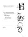
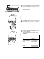
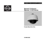
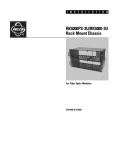
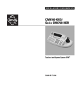
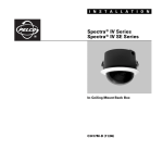
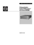
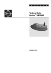
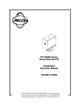
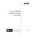
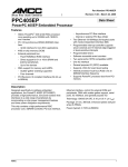
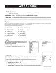
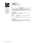
I N S T A L L A T I O N
Spectra III™ EVS
Pendant Back Box
C2493M (12/05)
Important Safety Instructions
1. Read these instructions.
2. Keep these instructions.
3. Heed all warnings.
4. Follow all instructions.
5. Do not use this apparatus near water.
6. Clean only with dry cloth.
7. Do not block any ventilation openings. Install in accordance with the manufacturer’s instructions.
8. Do not install near any heat sources such as radiators, heat registers, stoves, or other apparatus (including amplifiers) that produce heat.
9. Only use attachments/accessories specified by the manufacturer.
10. Use only with the cart, stand, tripod, bracket, or table specified by the manufacturer, or sold with the apparatus. When a cart is used, use caution when
moving the cart/apparatus combination to avoid injury from tip-over.
11. Refer all servicing to qualified service personnel. Servicing is required when the apparatus has been damaged in any way, such as power-supply cord
or plug is damaged, liquid has been spilled or objects have fallen into the apparatus, the apparatus has been exposed to rain or moisture, does not
operate normally, or has been dropped.
12. Installation should be done only by qualified personnel and conform to all local codes.
13. Unless the unit is specifically marked as a NEMA Type 3, 3R, 3S, 4, 4X, 6, or 6P enclosure, it is designed for indoor use only and it must not be installed
where exposed to rain and moisture.
14. Use only installation methods and materials capable of supporting four times the maximum specified load.
15. Use stainless steel hardware to fasten the mount to outdoor surfaces.
16. To prevent damage from water leakage when installing a mount outdoors on a roof or wall, apply sealant around the bolt holes between the mount and
mounting surface.
17. CAUTION: These servicing instructions are for use by qualified service personnel only. To reduce the risk of electric shock do not perform any servicing
other that contained in the operating instructions unless you are qualified to do so.
18. Only use replacement parts recommended by Pelco.
The product and/or manual may bear the following marks:
This symbol indicates that dangerous voltage constituting a risk of electric shock is present within this unit
This symbol indicates that there are important operating and maintenance instructions in the literature
accompanying this unit.
2
CAUTION:
RISK OF ELECTRIC SHOCK.
DO NOT OPEN.
C2493M (12/05)
Installation
.
1
Install the mount for the pendant dome. Refer to the instructions
supplied with the mount.
2
Open the hinged door to the back box. Push the tab lock towards the
wall of the unit and lift the door open. Pull power, alarm/auxiliary, and
network cable into the back box.
The following are the recommended maximum distances for 24 VAC
applications and are calculated with a 10 percent voltage drop.
(Ten percent is generally the maximum allowable voltage drop for
AC-powered devices.)
Total
VA
20 AWG
(0.5 mm2)
18 AWG
(1.0 mm2)
16 AWG
(1.5 mm2)
14 AWG
(2.5 mm2)
36
79 ft
(24 m)
125 ft
(38 m)
199 ft
(60 m)
316 ft
(96 m)
88
32 ft
(9 m)
51 ft
(15 m)
81 ft
(24 m)
129 ft
(39 m)
NOTE: Input power for the dome is 24 VAC only. Power consumption
is 36 VA per dome for indoor models and 88 VA for outdoor models.
Use a 24 VAC transformer with a minimum output of 36 VA per dome
for indoor applications and a minimum of 88 VA per dome for outdoor
applications.
3
C2493M (12/05)
Screw the back box onto the mount. For outdoor installations, apply
thread compound (provided) to the threads on the back box.
3
4
Connect the power wires to the circuit board inside the back box.
Connect any alarm and auxiliary circuits. Turn on the power to the
system. The green LED on the door indicates system power is on.
NOTE: Aux 1 – Maximum 2 A at low voltage (<40 V)
ALARMS
ALARM COM
AUX1
AUX COM
POWER
5
Connect a 10/100/1000BaseT network Cat5e (or better) cable to the
RJ-45 network connector located inside the back box. Check the LED
indicators located inside the back box to check unit status, network
status, and network activity.
Unit Status LED
Green
Unit is functioning normally.
Amber Unit is in configuration mode.
Red
Unit is in an error condition.
Network Status LED
Off
Unit is not connected to the network.
Amber Unit is connected to a 100BaseT network.
Red
Unit is connected to a 10BaseT network.
Network Activity LED
The LED flashes whenever the unit is sending or receiving network data.
6
4
Close the door to the back box. Attach the back box leash to the
lower dome.
C2493M (12/05)
SW1-1 is set to the ON position.
All other switches are set to the OFF position.
1 2 3 4 5 6 7 8
SW1
1 2 3 4 5 6 7 8
1
on SW2 on
SW3
7
No DIP switch settings are required for the system. Before installing the
dome drive verify that switch SW1-1 (SW1, switch 1) is set to the ON
position and all other switches are set to the OFF position.
The switches set the dome drive for Pelco’s D protocol, address 1,
2400 baud, and no termination.
ON
8
Install the dome drive. Line up the blue (A) and red (B) tabs with the blue
(A) and red (B) labels. Push in the tabs. Insert one side and then the
other side. Continue pushing on the ends of the tabs until both sides
click into place.
9
Install the lower dome. Tighten the Phillips pan head screws to secure
the lower dome to the back box.
A
To operate or program your Spectra III EVS dome drive, refer to the
following manuals:
C2493M (12/05)
Information Required
Where to Find Information
Spectra’s programmable
features, commands, and menu
structure
Spectra III Operation/
Programming manual supplied
with the dome drive or available
at www.pelco.com
How to control the dome drive
and access preset 95 with the
WS5050
Endura™ WS5000 Advanced
System Software Operation
manual supplied with the
WS5050 workstation or
available at www.pelco.com
How to control the dome drive
and access preset 95 with the
VCD5000
Endura VCD5000 Video Control
Display Operation manual
supplied with the VCD5000 or
available at www.pelco.com
5
Specifications
SYSTEM
Processor
Operating System
User Interface
GENERAL
PowerPC® 405EP
Linux®
Remote operation via WS5050 or
VCD5000
Construction
Back Box
Dome Drive
Bubble
Light Attenuation
Smoked
Clear
Chrome and Gold
Cable Entry (Back Box)
Weight (approximate)
Back Box
Standard Pendant
Environmental Pendant
Dome Drive
Lower Dome
Environment
Operating Temperature
Standard Pendant
ELECTRICAL
Input Voltage
Input Power
Fuse
Auxiliary Outputs
Alarm Inputs
18-30 VAC; 24 VAC nominal
36 VA nominal (without heaters)
88 VA nominal (with heaters)
1.25 A
1
7
VIDEO
Video Standards
Video Coding
Video Streams
Video Resolutions
4CIF
2CIF
CIF
QCIF
Video Inputs/Connectors
Video Switch
NTSC/PAL/EIA/CCIR composite
MPEG-4
2, simultaneous
NTSC
PAL
704 x 480
704 x 576
704 x 240
704 x 288
352 x 240
352 x 288
176 x 120
176 x 144
2, BNC, looping, 75¾, 1 Vp-p
Hi-Z, 75¾
Environmental Pendant
Maximum
Minimum
VIDEO ACTIVITY DETECTION
Zones
Zone Types
Sensitivity
3 plus background zone
Any shape, user-definable in 16 x 16 pixel
blocks
Adjustable
ENVIRONMENTAL PENDANT
Effective Projected Area (EPA)
Aluminum
Aluminum, thermo plastic
Acrylic
1/2 F-stop light loss
Zero light loss
2 F-stops light loss
Through 1.5-inch NPT pendant mount
Unit
Shipping
4.1 lb (1.86 kg)
4.4 lb (2.00 kg)
2.4 lb (1.09 kg)
0.6 lb (0.27 kg)
Indoor/outdoor
6 lb (2.72 kg)
6 lb (2.72 kg)
4 lb (1.81 kg)
2 lb (0.90 kg)
32° to 140°F (0° to 60°C) absolute
maximum operating temperature; 32° to
122°F (0° to 50°C) sustained maximum
operating temperature
(Assumes no wind chill factor; for
detailed test conditions, contact Pelco.)
140°F (60°C) absolute maximum;
122°F (50°C) sustained maximum
-60°F (-51°C) absolute minimum; minimal
icing at sustained minimum of
50°F (-45°C); prevents icing at sustained
minimum of -40°F (-40°C); de-ices
0.1 inch (2.5 mm) within 3 hours after
power-up
92 square inches (without mount);
138 square inches (with IWM Series
mount)
STANDARD PENDANT
13.0
(33.02)
13.0
(33.02)
6.00
(15.24)
6.00
(15.24)
9.4
(23.87)
8.7
(22.09)
NOTE: VALUES IN PARENTHESES ARE CENTIMETERS; ALL OTHERS ARE INCHES.
6
C2493M (12/05)
PRODUCT WARRANTY AND RETURN INFORMATION
WARRANTY
Pelco will repair or replace, without charge, any merchandise proved defective in material or
workmanship for a period of one year after the date of shipment.
Exceptions to this warranty are as noted below:
• Five years on FR/FT/FS Series fiber optic products and TW3000 Series unshielded twisted
pair transmission products.
• Three years on Genex® Series products (multiplexers, server, and keyboard).
• Three years on Camclosure® and fixed camera models, except the CC3701H-2,
CC3701H-2X, CC3751H-2, CC3651H-2X, MC3651H-2, and MC3651H-2X camera models,
which have a five-year warranty.
• Three years on PMCL200/300/400 Series LCD monitors.
• Two years on standard motorized or fixed focal length lenses.
• Two years on Legacy®, CM6700/CM6800/CM9700 Series matrix, and DF5/DF8 Series
fixed dome products.
®
®
™
• Two years on Spectra , Esprit , ExSite , and PS20 scanners, including when used in
continuous motion applications.
• Two years on Esprit and WW5700 Series window wiper (excluding wiper blades).
• Two years (except lamp and color wheel) on Digital Light Processing (DLP®) displays.
The lamp and color wheel will be covered for a period of 90 days. The air filter is not
covered under warranty.
• Eighteen months on DX Series digital video recorders, NVR300 Series network video
recorders, and Endura™ Series distributed network-based video products.
• One year (except video heads) on video cassette recorders (VCRs). Video heads will be
covered for a period of six months.
• Six months on all pan and tilts, scanners or preset lenses used in continuous motion
applications (that is, preset scan, tour and auto scan modes).
Pelco will warrant all replacement parts and repairs for 90 days from the date of Pelco
shipment. All goods requiring warranty repair shall be sent freight prepaid to Pelco, Clovis,
California. Repairs made necessary by reason of misuse, alteration, normal wear, or accident
are not covered under this warranty.
Pelco assumes no risk and shall be subject to no liability for damages or loss resulting from
the specific use or application made of the Products. Pelco’s liability for any claim, whether
based on breach of contract, negligence, infringement of any rights of any party or product liability, relating to the Products shall not exceed the price paid by the Dealer to Pelco for such
Products. In no event will Pelco be liable for any special, incidental or consequential damages
(including loss of use, loss of profit and claims of third parties) however caused, whether by
the negligence of Pelco or otherwise.
The above warranty provides the Dealer with specific legal rights. The Dealer may also have
additional rights, which are subject to variation from state to state.
If a warranty repair is required, the Dealer must contact Pelco at (800)þ289-9100 or
(559) 292-1981 to obtain a Repair Authorization number (RA), and provide the following
information:
1. Model and serial number
2. Date of shipment, P.O. number, Sales Order number, or Pelco invoice number
3. Details of the defect or problem
If there is a dispute regarding the warranty of a product which does not fall under the
warranty conditions stated above, please include a written explanation with the product when
returned.
Method of return shipment shall be the same or equal to the method by which the item was
received by Pelco.
RETURNS
In order to expedite parts returned to the factory for repair or credit, please call the factory at
(800) 289-9100 or (559) 292-1981 to obtain an authorization number (CA number if returned for
credit, and RA number if returned for repair).
All merchandise returned for credit may be subject to a 20% restocking and refurbishing
charge.
Goods returned for repair or credit should be clearly identified with the assigned CA or RA
number and freight should be prepaid. Ship to the appropriate address below.
If you are located within the continental U.S., Alaska, Hawaii or Puerto Rico, send goods to:
Service Department
Pelco
3500 Pelco Way
Clovis, CA 93612-5699
If you are located outside the continental U.S., Alaska, Hawaii or Puerto Rico and are
instructed to return goods to the USA, you may do one of the following:
If the goods are to be sent by a COURIER SERVICE, send the goods to:
Pelco
3500 Pelco Way
Clovis, CA 93612-5699 USA
If the goods are to be sent by a FREIGHT FORWARDER, send the goods to:
Pelco c/o Expeditors
473 Eccles Avenue
South San Francisco, CA 94080 USA
Phone: 650-737-1700
Fax: 650-737-0933
The materials used in the manufacture of this document and its components are compliant to the requirements of Directive 2002/95/EC.
This equipment contains electrical or electronic components that must be recycled properly to comply with Directive 2002/96/EC of the European Union
regarding the disposal of waste electrical and electronic equipment (WEEE). Contact your local dealer for procedures for recycling this equipment.
REVISION HISTORY
Manual #
C2493M
Date
12/05
Comments
Original version.
Pelco, the Pelco logo, Camclosure, Esprit, Genex, Legacy, and Spectra are registered trademarks of Pelco.
Endura and ExSite are trademarks of Pelco.
DLP is a registered trademark of Texas Instruments, Inc.
©Copyright 2005, Pelco. All rights reserved.
Worldwide Headquarters
3500 Pelco Way
Clovis, California 93612 USA
USA & Canada
Tel: 800/289-9100
Fax: 800/289-9150
International
Tel: 1-559/292-1981
Fax: 1-559/348-1120
www.pelco.com
ISO9001
Australia
| Canada | Finland | France | Italy | Russia | Singapore | Spain | Sweden | The Netherlands | United Arab Emirates | United Kingdom | United States