1
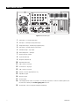
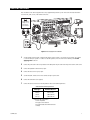
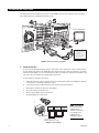
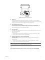
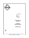
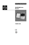
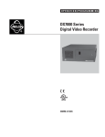
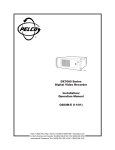
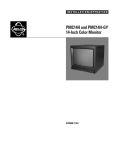
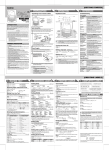
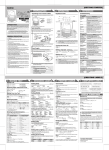
INSTALLATION MANUAL
®
DX7000 Series
Digital Video Recorder
C664M-B (8/02)
CONTENTS
Section
Page
IMPORTANT SAFEGUARDS AND WARNINGS .................................................................................................................................................................. 3
WELCOME .......................................................................................................................................................................................................................... 4
MOUNTING ........................................................................................................................................................................................................................ 5
FLAT SURFACE MOUNTING ...................................................................................................................................................................................... 5
EQUIPMENT RACK MOUNTING ................................................................................................................................................................................ 5
BACK PANEL LAYOUT ......................................................................................................................................................................................................... 6
BASIC INSTALLATION ......................................................................................................................................................................................................... 7
EXTENDED INSTALLATION ................................................................................................................................................................................................. 8
SPECIFICATIONS ................................................................................................................................................................................................................ 10
REGULATORY NOTICES ..................................................................................................................................................................................................... 11
WARRANTY AND RETURN INFORMATION ...................................................................................................................................................................... 11
LIST OF ILLUSTRATIONS
Figure
1
2
3
4
5
6
2
Page
Rack Ear Installation ............................................................................................................................................................................................. 5
Back Panel Layout ................................................................................................................................................................................................. 6
Basic Equipment Installation ................................................................................................................................................................................ 7
Extended Equipment Installation .......................................................................................................................................................................... 8
PTZ Installation ..................................................................................................................................................................................................... 8
Bottom View of the RS-422 Converter .................................................................................................................................................................. 9
C664M-B (8/02)
IMPORTANT SAFEGUARDS AND WARNINGS
Prior to installation and use of this product, the following WARNINGS should be observed.
1.
Installation and servicing should be done only by qualified service personnel and conform to all local codes.
2.
Unless the unit is specifically marked as a NEMA Type 3, 3R, 3S, 4, 4X, 6, or 6P enclosure, it is designed for indoor use
only and it must not be installed where exposed to rain and moisture.
3.
Only use replacement parts recommended by Pelco.
4.
After replacement/repair of this unit’s electrical components, conduct a resistance measurement between line and
exposed parts to verify the exposed parts have not been connected to line circuitry.
5.
For USA and Canada, use only a UL listed CSA labeled detachable power cord, 3-conductor, 18 AWG, SVT, or SJT type,
round type plug, parallel blade, cord connector body IEC 320 style to mate with inlet on product.
6.
To reduce the risk of fire, use only No. 2 AWG or larger telecommunications line cord.
IMPORTANT: The only way to disconnect power completely is to unplug the power cord. Make sure at least one end of the
power cord is within easy reach so that the unit can be unplugged when required.
CAUTION: DANGER OF EXPLOSION IF BATTERY IS INCORRECTLY REPLACED. REPLACE ONLY WITH THE SAME OR
EQUIVALENT TYPE RECOMMENDED BY THE MANUFACTURER. DISCARD USED BATTERIES ACCORDING TO THE
MANUFACTURER’S INSTRUCTIONS.
The product and/or manual may bear the following marks:
This symbol indicates that dangerous voltage constituting a risk of
electric shock is present within this unit.
CAUTION:
RISK OF ELECTRIC SHOCK.
DO NOT OPEN.
This symbol indicates that there are important operating and
maintenance instructions in the literature accompanying this unit.
Please thoroughly familiarize yourself with the information in this manual prior to installation and operation.
WARNING
This product is factory set to operate on 115 VAC.
For 230 VAC operation, move the switch to the 230 VAC
position before applying power to the unit.
01204
C664M-B (8/02)
3
WELCOME
Thank you for purchasing Pelco’s DX7000 Series, high-quality digital video recorder (DVR). Your new system combines the
functions of a recorder and multiplexer into a product with versatile recording and playback functions.
The following equipment is supplied with the DX7000 Series DVR:
Qty
1
1
1
1
2
2
1
1
6
2
4
1
1
Description
Keyboard
Mouse
RS-422 communication converter, including power adapter
9-pin to 25-pin adapter
Power cables (1 USA standard and 1 European standard)
Keys for front panel
Microsoft Windows® 98 CD
DX7000 Remote Site Software CD
10-32 x .75-inch black mounting screws and washers
Rack Mount ears, handles, and hardware (assembly required)
Rubber feet
Installation manual
Operation/Programming manual
NOTE: An uninterruptible power supply (UPS) is not supplied with the DVR. If required, Pelco recommends a device with the
following specifications:
Capacity – 350 VA, 210 watts
Output voltage – 115V ± 8% (on battery)
Frequency range – 47 Hz to 63 Hz
4
C664M-B (8/02)
MOUNTING
The DX7000 may be placed on a flat surface, such as a shelf, or it can be installed in a 19-inch (48.26 cm) equipment rack.
FLAT SURFACE MOUNTING
Before placing the unit on a flat surface, attach the rubber feet (supplied) to the bottom of the DVR. The unit may scratch the
surface if the rubber feet are not installed.
EQUIPMENT RACK MOUNTING
To install the unit in an equipment rack:
1.
Attach the handles to the rack ears using four of the Phillips flat head screws (provided). Refer to Figure 1.
2.
Remove the top screw and bottom screw from the left and right side of the DVR. Remove the side plates. Refer to Figure 1.
3.
Use the screws removed from the sides of the DVR and attach the rack ears to the unit. Refer to Figure 1.
4.
Use four of the supplied 10-32 x .75-inch black screws and finishing washers and mount the assembly to a 19-inch (48.26 cm)
rack or console. Installation of the assembly may require two persons. Pelco recommends 1RU spacing between units.
REMOVE
PLATE
INSTALL
RACK
EAR
Figure 1. Rack Ear Installation
IMPORTANT: Slots and openings in the cabinet provide ventilation and prevent it from overheating. Do not block these
openings. Never place the DVR near or over a radiator or heat register. Do not place it in a built-in installation, such as a rack,
unless proper ventilation is provided or Pelco’s instructions have been followed.
C664M-B (8/02)
5
BACK PANEL LAYOUT
1
CAM1
CAM2
CAM3
CAM4
CAM5
CAM6
CAM7
CAM8
CAM9
CAM10
CAM11
CAM12
3
CAM13
SENSOR
1 2
3
CAM14
4
5
6
7
CAM15
8
CAM16
RELAY
1 2 3
COM
VIDEO
OUTPUT
4 5 6 7
2
18
5
COM
4
2
1
NTSC
PAL
8
16
12
17 15 14 13 11 10 9
1
19
8
Audio
L-OUT
L-IN
MIC
7
NTSC
PAL
ACT LINK
6
2
Figure 2. Back Panel Layout
1
2
3
4
5
6
7
8
9
10
11
12
13
14
15
16
17
18
19
6
Camera Inputs – 8 or 16 BNC camera inputs
Alarm Inputs – 8 normally closed dry contact inputs
Analog Monitor Output – One BNC output (sequencing only)
Relay Outputs – 8 normally open dry contact outputs
VGA Monitor Output – 15-pin output
Ethernet Adapter Port – 10/100 port
NTSC/PAL Selection Switches
Joystick Port (Not used)
Microphone Jack (Not used)
Audio IN/OUT (Not used)
COM 2 Serial Port – 9-pin port
LPT1 Printer Port – 25-pin port
COM 1 Serial Port – 9-pin port
USB Ports – For Pelco-supported devices only
Keyboard (PS/2) Input
Mouse (PS/2) Input
AC Power Output
Power Voltage Selection Switch – This product is set at the factory to operate on 115 VAC. For 230 VAC operation, move
the switch to the 230 VAC position before applying power to the unit.
AC Power Input – Please see Important Safeguards and Warnings.
C664M-B (8/02)
BASIC INSTALLATION
Basic installation covers all the equipment necessary to program and operate the system. Refer to the Extended Installation
section for PTZ, alarm, sensors, and network connections.
Verify that the
voltage is set
correctly for
your location
115
OR
7
aremaC DCC roloC PSD
6
230
1
NTSC
3
2
4
PAL
5
Figure 3. Basic Equipment Installation
1
Set the Voltage Selection Switch - Verify that the voltage selection switch is set correctly for your location. This product
is set at the factory to operate on 115 VAC. For 230 VAC operation, move the switch to the 230 VAC position before
applying power to the unit.
2
Connect the power cord to the AC input located on the back panel. Plug the other end of the power cord into an AC outlet.
3
Connect the keyboard to the bottom PS/2 input.
4
Connect the mouse to the top PS/2 input.
5
Set the NTSC/PAL switches to the correct camera setting for your location.
6
Connect the VGA monitor (not supplied).
7
Connect the cameras. Refer to the following table for video coaxial cable requirements:
Video Coaxial Cable Requirements
Cable Type*
Maximum Distance
RG59/U
RG6/U
RG11/U
750 ft (229 m)
1,000 ft (305 m)
1,500 ft (457 m)
* Minimum cable requirements:
75 ohms impedance
All-copper center conductor
All-copper braided shield with 95% braid
coverage
C664M-B (8/02)
7
EXTENDED INSTALLATION
Extended installation covers installation of accessories for the DX7000. Refer to the Basic Installation section to install the
basic equipment necessary to program and operate the system.
5
4
Analog (spot) Monitor
3
2
1
Network
NOTE: A standard European
plug is attached to the
power adapter. To convert
the adapter to the USA
standard loosen the Phillips
head screw and remove
the European plug.
Power
Figure 4. Extended Equipment Installation
1
PTZ (RS-422 Converter)
To control receivers with pan/tilt and zoom functions, such as Pelco’s Esprit™ and Spectra® systems, you must install the
RS-422 communication converter. The DX7000 DVR cannot operate PTZ receivers if the RS-422 converter is not installed
and the PTZ receiver address is not set to accept D protocol control. For information on setting the receiver address for Dtype control, refer to the documentation supplied with the PTZ receiver.
Do the following to install the RS-422 converter:
a.
Connect the control wires from the receiver to the RS-422 converter (refer to Figure 5). The DX7000 can support up
to 16 PTZ devices, at a maximum of 4,000 feet (1,219 m).
b.
Set the DTE/DCE switch located on the bottom of the converter to DCE (refer to Figure 6).
c.
Plug the RS-422 converter into the 9-pin to 25-pin adapter.
d.
Plug the pin converter into the COM 1 Port.
e.
Attach the power adapter to the RS-422 converter.
f.
Plug power adapter into a power source.
PTZ
PTZ
RX RX TX TX
+ - + -
RX RX TX TX
+ - + -
PTZ
THE LAST PTZ IN
SERIES TERMINATE
RX RX TX TX
+ - + -
NOTE: The DX7000 may
be connected to Pelco’s
CM9760-CXT-A for
Coaxitron® control. Refer
to the manual for the
CM9760-CXT-A for
installation instructions.
SUPPORTS UP TO 16 PTZ
MAXIMUM: 4,000 FEET (1,219M)
Figure 5. PTZ Installation
8
C664M-B (8/02)
DTE
DCE
DC 9V
SET TO DCE
Connection
A
B
+
T+
TRR+
R+
RTT+
T+T-R-R+
Figure 6. Bottom View of the RS-422 Converter
2
TCP/IP Access
Consult your network administrator to avoid possible network conflicts. For TCP/IP access, connect the DX7000 to a
10/100 Ethernet network. Use a standard UTP Cat5 cable with RJ-45 connectors. Plug the cable into the LAN port located
on the back of the unit. Use a router with multi-casting when connecting to a WAN network.
3
Analog Spot Monitor (Sequencing only)
You can connect an analog monitor to the DX7000. This monitor is for viewing purposes only. Programming menus and
bars are not displayed on the screen. All enabled cameras are displayed on the monitor in a sequential order.
Connect the analog spot monitor to the output labeled VIDEO OUTPUT.
4
Sensor (Alarm) Inputs
The DX7000 has eight normally closed dry contact sensor inputs. Sensor inputs require an open circuit contact, such as a
switch or relay, to trigger an alarm.
To wire a sensor input:
a. Connect one wire from the source device (for example, a door) to one of the sensor input terminals 1 through 8.
b. Connect a second wire from the source device to the COM terminal.
5
Relay Outputs (Maximum power rating 125 VAC, 0.5A; 30VDC, 1A)
The DX7000 has eight normally opened dry contact relay outputs. A signal from a output will operate the device
connected to the output.
To wire a relay output:
a. Connect one wire from the device (for example, an alarm) to one of the relay output terminals 1 through 8.
b. Connect a second wire from the relay device to the COM terminal.
NOTE: The sensor input does not have to correspond numerically to the relay output. All sensor input and relay output actions
are linked through programming. Refer to the Operation/Programming manual for details.
Refer to the Operation/Programming manual for instructions on how to set up and operate the DX7000 DVR.
C664M-B (8/02)
9
SPECIFICATIONS
ELECTRICAL/VIDEO
Input Voltage:
Signal System:
CPU and RAM
DX7008:
DX7016:
Resolution
NTSC:
PAL:
Compression:
Compressed Image Size:
Video Inputs:
Video Outputs:
Alarm Inputs:
Control Outputs:
Remote Control:
Pan/Tilt/Zoom Control:
320 x 240
384 x 288
M-JPEG
352 x 240; average 6 KB
8 or 16, depending on model
2 (1 SVGA, 1 analog)
8
8
Full remote control via PSTN, ISDN, TCP/IP
RS-422 interface to receivers
GENERAL
Operating Temperature:
Relative Humidity:
Dimensions:
41° to 104°F (5° to 40°C)
Maximum 80% non-condensing
7 (H) x 17 (W) x 18 (D) inches (17.78 x 43.18 x 45.72 cm)
100-240 VAC switchable, 50/60 Hz
NTSC/PAL
Celeron®, 128 MB
Pentium® III, 128 MB
(Design and product specifications subject to change without notice.)
10
C664M-B (8/02)
REGULATORY NOTICES
This equipment has been tested and found to comply with the limits of a Class B digital device, pursuant to part 15 of the FCC
rules. These limits are designed to provide reasonable protection against harmful interference in a residential installation. This
equipment generates, uses, and can radiate radio frequency energy and, if not installed and used in accordance with the
instructions, may cause harmful interference to radio communications. However there is no guarantee that the interference
will not occur in a particular installation. If this equipment does cause harmful interference to radio or television reception,
which can be determined by turning the equipment off and on, the user is encouraged to try and correct the interference by one
or more of the following measures:
•
Reorient or relocate the receiving antenna.
•
Increase the separation between the equipment and the receiver.
•
Connect the equipment into an outlet on a circuit different from that to which the receiver is connected.
•
Consult the dealer or an experienced radio/TV technician for help.
WARRANTY AND RETURN INFORMATION
WARRANTY
Pelco will repair or replace, without charge, any merchandise proved defective in material or
workmanship for a period of one year after the date of shipment. Exceptions to this warranty are
as noted below:
• Five years on Pelco manufactured cameras (CC3500/CC3600/CC3700 and MC3500/MC3600
Series); two years on all other cameras.
• Three years on Genex® Series (multiplexers, server, and keyboard).
• Two years all standard motorized or fixed focal length lenses.
• Two years on Legacy®, Camclosure™ Camera Systems, CM6700/CM6800/CM8500/CM9500/
CM9740/CM9760 Matrix, DF5 and DF8 Series Fixed Dome products.
• Two years on Spectra®, Esprit™, and PS20 Scanners, including when used in continuous
motion applications.
• Two years on WW5700 series window wiper (excluding wiper blades).
• Eighteen months on DX Series digital video recorders.
• One year (except video heads) on video cassette recorders (VCRs). Video heads will be
covered for a period of six months.
• Six months on all pan and tilts, scanners or preset lenses used in continuous motion applications (that is, preset scan, tour and auto scan modes).
If a warranty repair is required, the Dealer must contact Pelco at (800) 289-9100 or (559) 292-1981 to
obtain a Repair Authorization number (RA), and provide the following information:
1. Model and serial number
2. Date of shipment, P.O. number, Sales Order number, or Pelco invoice number
3. Details of the defect or problem
If there is a dispute regarding the warranty of a product which does not fall under the warranty conditions
stated above, please include a written explanation with the product when returned.
Method of return shipment shall be the same or equal to the method by which the item was received by
Pelco.
RETURNS
In order to expedite parts returned to the factory for repair or credit, please call the factory at (800) 2899100 or (559) 292-1981 to obtain an authorization number (CA number if returned for credit, and RA
number if returned for repair).
All merchandise returned for credit may be subject to a 20% restocking and refurbishing charge.
Pelco will warrant all replacement parts and repairs for 90 days from the date of Pelco
shipment. All goods requiring warranty repair shall be sent freight prepaid to Pelco, Clovis,
California. Repairs made necessary by reason of misuse, alteration, normal wear, or accident
are not covered under this warranty.
Pelco assumes no risk and shall be subject to no liability for damages or loss resulting from the
specific use or application made of the Products. Pelco’s liability for any claim, whether based on
breach of contract, negligence, infringement of any rights of any party or product liability, relating
to the Products shall not exceed the price paid by the Dealer to Pelco for such Products. In no
event will Pelco be liable for any special, incidental or consequential damages (including loss of
use, loss of profit and claims of third parties) however caused, whether by the negligence of
Pelco or otherwise.
The above warranty provides the Dealer with specific legal rights. The Dealer may also have
additional rights, which are subject to variation from state to state.
Goods returned for repair or credit should be clearly identified with the assigned CA or RA number and
freight should be prepaid. Ship to the appropriate address below.
If you are located within the continental U.S., Alaska, Hawaii or Puerto Rico:
Service Department
Pelco
3500 Pelco Way
Clovis, CA 93612-5699
If you are located outside the continental U.S., Alaska, Hawaii or Puerto Rico:
Intermediate Consignee
Ultimate Consignee
American Overseas Air Freight
Pelco
320 Beach Road
3500 Pelco Way
Burlingame, CA 94010
Clovis, CA 93612-5699
USA
USA
REVISION HISTORY
Manual #
C664M
C664M-A
C664M-B
Date
4/02
5/02
8/02
Comments
Original version.
Revised installation instructions.
Added information to Safeguards and Warnings.
® Pelco, the Pelco logo, Spectra, Genex, Legacy, and Coaxitron are registered trademarks of Pelco.
® Windows is a registered trademark of Microsoft Corporation.
® Pentium and Celeron are registered trademarks of Intel Corporation.
C664M-B (8/02)
™ Esprit and Camclosure are trademarks of Pelco.
© Copyright 2002, Pelco.
All rights reserved.
11
®
World Headquarters
3500 Pelco Way
Clovis, California 93612 USA
USA & Canada
Tel: 800/289-9100
Fax: 800/289-9150
International
Tel: 1-559/292-1981
Fax: 1-559/348-1120
www.pelco.com
ISO9001
Orangeburg, New York Las Vegas, Nevada Eindhoven, The Netherlands Wokingham, United Kingdom Montreal, Canada