1
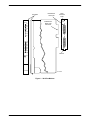
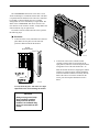
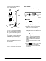
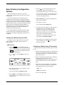
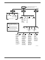
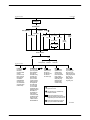
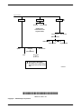
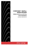
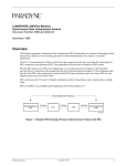
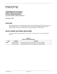
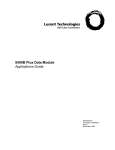
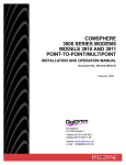
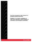
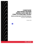
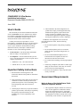
TM COMSPHERE 3811Plus Modem Installation Instructions Document Number 3980-A2-GZ41-20 June 1998 User’s Guide 4. When installed in the final configuration, the product must comply with the applicable Safety Standards and regulatory requirements of the country in which it is installed. If necessary, consult with the appropriate regulatory agencies and inspection authorities to ensure compliance. This document provides basic installation instructions for the COMSPHERE 3811Plus (Model 3981) modem. For complete configuration and operation instructions, refer to the COMSPHERE 3800Plus Modems User’s Guide (Document Number 3980-A2-GB30). Contact your local sales representative, service representative, or distributor directly for any help needed. For additional information concerning warranty, sales, service, repair, installation, documentation, training, distributor locations, or Paradyne worldwide office locations, use one of the following methods: • Via the Internet: Visit the Paradyne World Wide Web site at http://www.paradyne.com • Via Telephone: Call our automated call system to receive current information via fax or to speak with a company representative. In addition, if the equipment is to be used with telecommunications circuits, take the following precautions: • Never install telephone wiring during a lightning storm. • Never install telephone jacks in wet locations unless the jack is specifically designed for wet locations. • Never touch uninsulated telephone wires or terminals unless the telephone line has been disconnected at the network interface. • Use caution when installing or modifying telephone lines. — Within the U.S.A., call 1-800-870-2221 — Outside the U.S.A., call 1-727-530-2340 • Avoid using a telephone (other than a cordless type) during an electrical storm. There may be a remote risk of electric shock from lightning. Important Safety Instructions • Do not use the telephone to report a gas leak in the vicinity of the leak. 1. Read and follow all warning notices and instructions marked on the product or included in the manual. Government Requirements 2. Slots and openings in the cabinet are provided for ventilation. To ensure reliable operation of the product and to protect it from overheating, these slots and openings must not be blocked or covered. Notice to Users of the United States Public Switched Telephone Network 3. General purpose cables may be provided with this product. Special cables, which may be required by the regulatory inspection authority for the installation site, are the responsibility of the customer. 3980-A2-GZ41-20 June 1998 1. This equipment complies with Part 68 of the FCC rules. On the equipment is a label that contains, among other information, the FCC registration number and ringer equivalence number (REN) for this equipment. The label is located on the circuit card assembly of the 3811Plus. If requested, this 1 information must be provided to the telephone company. commission, public service commission, or corporation commission for information.) 2. The Universal Service Order Code (USOC) for Permissive mode is RJ21X. The Canadian equivalent to the USOC is CA21A. 9. The Telephone Consumer Protection Act of 1991 makes it unlawful for any person to use a computer or other electronic device to send any message via a telephone fax machine unless such a message clearly contains, in a margin at the top or bottom of each transmitted page, or on the first page of the transmission, the date and time it is sent, and an identification of the business, or other entity, or other individual sending the message, and the telephone number of such business, or other entity, or individual. 3. The Ringer Equivalence (REN) is used to determine the quantity of devices which may be connected to the telephone line. Excessive RENs on the telephone line may result in the devices not ringing in response to an incoming call. In most, but not all areas, the sum of the RENs should not exceed five (5.0). To be certain of the number of devices that may be connected to the line, as determined by the total RENs, contact the telephone company to determine the maximum RENs for the calling area. 4. If the 3811Plus modem causes harm to the telephone network, the telephone company will notify you in advance that temporary discontinuance of service may be required. But if advance notice is not practical, the telephone company will notify the customer as soon as possible. Also, you will be advised of your right to file a complaint with the FCC if you believe it is necessary. 5. The telephone company may make changes in its facilities, equipment, operations, or procedures that could affect the operation of the equipment. If this happens, the telephone company will provide advance notice in order for you to make the necessary modifications in order to maintain uninterrupted service. 6. If you require technical assistance or repair, see Equipment Support and Warranty on page 4. If the trouble is causing harm to the telephone network, the telephone company may request that you remove the equipment from the network until the problem is resolved. 7. The user is not authorized to repair or modify the equipment. 8. This equipment cannot be used on public coin service provided by the telephone company. Connection to Party Line Service is subject to state tariffs. (Contact the state public utility 2 In order to program this information, follow the steps outlined in the manual supplied with your fax software. Notice to Users of the Canadian Public Switched Telephone Network The Canadian Department of Communications label identifies certified equipment. This certification means that the equipment meets certain telecommunications network protective, operational, and safety requirements. The Department does not guarantee the equipment will operate to the user’s satisfaction. Before installing this equipment, users should ensure that it is permissible to be connected to the facilities of the local telecommunications company. The equipment must also be installed using an acceptable method of connection. In some cases, the company’s inside wiring associated with a single line individual service may be extended by means of a certified connector assembly (telephone extension cord). The customer should be aware that compliance with the above conditions may not prevent degradation of service in some situations. Repairs to certified equipment should be made by an authorized Canadian maintenance facility designated by the supplier. Any repairs or alterations made by the user to this equipment, or equipment malfunctions, may give the telecommunications company cause to request the user to disconnect the equipment. Users should ensure for their own protection that the electrical ground connections of the power utility, telephone line and internal metallic water pipe system, if present, are connected together. This precaution may be particularly important in rural areas. June 1998 3980-A2-GZ41-20 This modem is suitable for connection to BT circuits with signalling at a nominal frequency of 2280 Hz and may be connected to multipoint or point-to-point circuits. The apparatus does not require signalling or otherwise use the frequency range 0 –200 Hz. CAUTION Users should not attempt to make such connections themselves, but should contact the appropriate electric inspection authority, or electrician, as appropriate. No d.c. interaction is intended between the modem and the telephone network. The Load Number for this equipment is on the label on the modem. The Load Number (LN) assigned to each terminal device denotes the percentage of the total load to be connected to a telephone loop which is used by the device to prevent overloading. The termination on a loop may consist of any combination of devices subject only to the requirement that the total of the Load Numbers of all devices does not exceed 100. United Kingdom Ringer Equivalence Number The Ringer Equivalence Number (REN) is a customer guide indicating approximately the maximum number of items of apparatus that should be connected simultaneously to the telephone line. The sum of the RENs should not exceed four. This value includes any BT-provided instrument which may be assumed to have a REN of 1 unless marked otherwise. The REN of this modem is 1. This apparatus may be directly connected to a speechband circuit or connected to a relevant branch system for speechband circuits. All European Countries Safety Notice Interconnection circuits between this modem and any other equipment should be such that the equipment continues to comply with the requirements of EN41003 for TNV (Telephone Network Voltage) circuits and EN60950 for SELV (Safety Extra Low Voltage) circuits after making connection between circuits. Japan Notices Connection to Leased Lines If any other apparatus, including cable or wiring, is connected between the apparatus and the point of connection to any speechband circuit, then all that other apparatus shall comply with the following: This equipment is classified in the 1st Class category. When used in a residential area or in an adjacent area thereto, radio interference may be caused to radios and TV receivers, etc. VCCI-1 1. The overall transmission characteristics of all that other apparatus shall be such as to introduce no material effect upon the electrical conditions presented to one another by the apparatus and the speechband circuit; and 2. All that other apparatus shall comprise only: Restrictions (i) apparatus approved for the purpose of connection between the apparatus and a speechband circuit; and (ii) cable or wiring complying with a code of practice for the installation of equipment covered by this part of BS 6328 or such other requirements as may be applicable. 3980-A2-GZ41-20 Due to JATE (Japan Approvals Institute for Telecommunications Equipment) regulations, only three attempts to dial a number are permitted in a 3-minute period. If a fourth attempt is made to dial the same number, the modem returns the ERROR return code. This restriction applies to the number dialed from the June 1998 3 Installation command line or from a directory. An occurrence of the restriction is canceled when a different number is dialed, or when three minutes have elapsed. Customer-Supplied Equipment Equipment Warranty and Support Technical Support Contact your local sales representative, service representative, or distributor directly for any help needed. For additional information concerning warranty, sales, service, repair, installation, documentation, training, distributor locations, or Paradyne worldwide office locations, use one of the following methods: The 3811Plus modem (see Figure 1) is designed for installation in a COMSPHERE 3000 Series Carrier which supplies operating power and the dial-line and/or leased-line network connections. For power, dial-line, leased-line, Network Interface Module (NIM), and network management cabling information, refer to the COMSPHERE 3000 Series Carrier Installation Manual (Document Number 3000-A2-GA31). In addition to the carrier, the following customer-supplied equipment may be required for the installation of a 3811Plus modem: • A Shared Diagnostic Unit (SDU, required for network management applications and multiple carriers). • Via the Internet: Visit the Paradyne World Wide Web site at http://www.paradyne.com • A Shared Diagnostic Control Panel (SDCP). • Via Telephone: Call our automated call system to receive current information via fax or to speak with a company representative. • One 6-position to 6-position modular cord (required for network management applications). • Two 50-pin mass termination cables, one NIM for modems installed in Slots 1–8, and one NIM for modems installed in Slots 9–16 (required for dial-line applications). — Within the U.S.A., call 1-800-870-2221 — From outside the U.S.A., call 727-530-2340 • One of the following dial or leased network interfaces: Equipment Service After opening the modem’s package, check for damage and verify that the following items are present: — 50-pin to modular cable (RJ11C) for dial permissive applications • 3811Plus modem — 50-pin to modular cable (JM8) for leased line applications • Rear connector plate with DB-25-P edge card connector Examine the equipment carefully upon arrival. If there is an obvious defect or you experience trouble please contact your sales or service representative (as appropriate) for repair or warranty information. If the product needs to be returned to the company service center for repair, contact them directly for return instructions using one of the following methods: • Via the Internet: Visit the Paradyne World Wide Web site at http://www.paradyne.com • An RS-232 DTE cable with a DB25 connector at one end and a connector appropriate to your DTE at the other end. If the modem is to be managed by a network management system, an SDU must be supplied and properly connected to the network management controller. For proper network management connection to the SDU, refer to the appropriate network management system user’s guide. • Via Telephone: Call our automated call system to receive current information via fax or to speak with a company representative. — Within the U.S.A., call 1-800-870-2221 — From outside the U.S.A., call 727-530-2340 4 June 1998 3980-A2-GZ41-20 EIA232/V.24 Connector Faceplate Pwr Alrm 142 EIA232/V.24 Edge Card Connector EIA232/V.24 Status Test Dial 125 Rear Connector Plate RI Busy Serv TXD 104 RXD 105 RTS 106 CTS 107 DSR 108 DTR 109 LSD Front Panel V.35 (3600/3500) 103 RS366A/V.25 (3800) SQ Unused Spkr 3811Plus 496-14488-02 Figure 1. 3811Plus Modem 3980-A2-GZ41-20 June 1998 5 The COMSPHERE 3000 Series Carrier has 17 slots which can hold up to 16 modems and one SDU. The SDU is required when the modems in the carrier are controlled by an NMS, or when multiple carriers in a cabinet configuration are to be controlled by a single SDCP. The SDCP of the COMSPHERE 3000 Series Carrier is the user interface to the 3811Plus modem. A single SDCP can control modems in up to eight carriers. To install a 3811Plus modem into the carrier, perform the following steps. Procedure 1. At the rear of the carrier, install the rear connector plate. Make sure the plate uses the same slot position as that intended for the modem. 25-Pin DTE Connectors 2. At the front of the carrier, hold the modem vertically, with the latch on its faceplate in the open position, and insert it into the top and bottom card guides of one of the slots numbered 1–16. V.35 (3600/3500) RS366A/V.25 (3800) EIA232/V.24 495-14797 Slide the modem into the slot, aligning the modem with the rear connector plate, until the backplane connector and DTE connector seat firmly into the back of the carrier. To lock the modem into the carrier, press the faceplate latch until a click is heard. P21 496-14906 Loosely fasten the plate. This allows for slight adjustments later when installing the modem. CAUTION Always use a ground strap when handling a modem. Always store a 3811Plus modem in an antistatic bag when it is removed from the carrier. 6 June 1998 3980-A2-GZ41-20 Check the SDCP 3. Rotate the circuit pack lock(s) into the closed position, and tighten the screw. If an SDCP is installed, verify that the SDCP can be used to control the modem. Perform the following steps. Circuit Pack Lock Carrier Slots 1–16 SDU 1 2 3 4 5 6 7 8 9 10 11 12 13 14 15 16 Select OK Closed (Locked) Circuit Card Guides Select Key Alarm BckUp Test EC Status Indicators F1 F2 F3 Keypad COMSPHERE 3000 LCD Display 496-12348a-03 Procedure 1. Press the Select key on the SDCP. The cursor appears in the two-digit slot selection entry. Open (Unlocked) 2. Press the key to position the cursor on the two-digit carrier selection entry. Latch 3. Press the F1 (↑) or F2 (↓) key until the carrier number you want appears on the LCD. 495-14813 The carrier number selection has a range of 1 to 8. With an SDU installed, a single SDCP can control up to eight carriers. 4. If the carrier is connected to power, the Power LED on the faceplate of the 3811Plus lights up. After several seconds the modem completes its power-up self-test in which all faceplate LEDs light up. key to position the cursor on the slot 4. Press the selection entry. If the modem fails, or an alarm condition exists, the Alrm LED on the faceplate lights up or flashes. It may be possible to run a diagnostic self-test from the SDCP. See Test Branch in the COMSPHERE 3800Plus Modems User’s Guide. 5. Press the F1 (↑) or F2 (↓) key until the slot number (1–16) you want appears on the LCD. (Ignore the AB designator that appears on the LCD since it is not applicable to the 3811Plus modem.) Return to the rear of the carrier and tighten the rear connector plate. The Front Panel LED on the modem’s faceplate lights up. 5. Connect an RS-232D DTE cable to the top connector of the rear connector plate. (The bottom connector is unused.) 6. Press the Select key to place the SDCP in direct communication with the selected modem. The LCD displays the Top-Level menu for the selected modem. 6. Connect the other end of the cable to your DTE. 7. Configure the modem as described in the following section, Select Factory Configuration Options. 3980-A2-GZ41-20 June 1998 7 Select Factory Configuration Options key until the appropriate factory 5. Press the preset appears on the LCD, and press the corresponding function key to select your choice. If you select Sync Leased, a new prompt asks you to select Answer Mode (F1) or Originate Mode (F3). Press the appropriate key. After the modem passes the power-up self-test, configure it for operation using one of the factory preset configurations. The 3811Plus modem has several factory preset templates that contain the proper configuration options (straps) for different environments. Modems are shipped from the factory with the Async Dial default configuration options stored in memory. To prepare the modem for Sync Dial, Sync Leased, UNIX Dial, Cellular (Mobile), or Cellular (PSTN), you must change the factory setting, using either the SDCP or the AT command &Fn, as described in the following sections. 6. Choose Function now appears and displays the Edit and Save functions. 7. Press the F3 key (Save). The LCD displays Sav EditArea to. 8. The Active (Saved), Customer 1, and Customer 2 configuration areas are nonvolatile memory locations. Active (Saved) contains the most recently saved changes to any configuration options. In the event of power loss, the modem retrieves these configuration options. The Cellular (Mobile) and Cellular (PSTN) settings (and the analogous AT commands &F5 and &F6) are available only if Enhanced Throughput Cellular (ETC) is installed. Press the F1 key to select Active (Saved). The LCD displays Command Complete. Configuring a Modem Using the SDCP 9. The modem is now configured with the selected key to return to factory template. Press the the Top-Level menu. To change a factory template from the Async Dial preset configuration using the SDCP, perform the following steps. Procedure 1. Press the Select key on the SDCP. Use the function keys to enter the carrier number and slot number of the modem to be configured. Press the Select key again. The Front Panel LED of the selected modem lights up. 2. Press the view. Configuring a Modem Using AT Commands When using AT commands, the following criteria must be met: • Make sure the asynchronous DTE’s communication software is configured for 10-bit character format (including the start bit); for example, 8 data bits, no parity, and 1 stop bit. key until Configure comes into Idle : 28.8 Test F1 • Make sure the DTE (RS-232D) cable is attached to the DTE connector on the rear of the COMSPHERE 3000 Series Carrier, and the correct serial communications port on the asynchronous DTE. Configure F2 F3 • On initial power-up, the modem is in Command mode. To verify that the modem is connected and functioning properly, enter the following: 3. Press the function key below Configure to select the Configure branch. TYPE: AT PRESS: Return (Enter) The LCD now displays Ld EditArea frm. The screen displays OK. key until Factory comes into view, 4. Press the then press the F1 key to display the factory preset configurations. 8 June 1998 3980-A2-GZ41-20 Menu Structure To change a factory template using AT commands, perform the following steps. The menu tree accessible from the SDCP contains the following branches: Procedure 1. Enter the appropriate factory configuration command (&Fn) followed by the &W0 command to store the configuration in Active (Saved) and the Z command to reset the modem. Call Setup Used to dial, disconnect, and answer telephone calls as well as store up to 10 telephone numbers in directory locations. Status Used to monitor the current status of the VF line and DTE interface as well as view the identity of the modem. Test Used to begin and end various modem tests. Configure Used to change and save the modem’s configuration options. Control Used to control the modem’s hardware and software functions. Remote Used to access and control a remote 3800Plus series modem. Security Used to control the modem’s dial access security. Appears only if the optional security feature is installed. TYPE: AT&Fn&W0Z Where: n is one of the following Factory configurations: 0 is Async Dial 1 is Sync Dial 2 is Sync Leased (Answer Mode) 3 is UNIX Dial 4 is Sync Leased (Originate Mode) 5 is Cellular (Mobile) 6 is Cellular (PSTN) PRESS: Return (Enter) 2. The selected factory configuration is saved and the modem is reset. Synchronous factory preset configurations (&F1, &F2, and &F4) inhibit AT command control. To regain AT command control, you must use the SDCP to load a different factory preset configuration. The AT commands &F5 and &F6 are available only if Enhanced Throughput Cellular (ETC) is installed. 3980-A2-GZ41-20 The following pages show the general menu structure of the SDCP displays. The model, installed features, and configuration options all may affect what is actually displayed at each level of the menus. June 1998 9 Displays current status of modem along with data rate and error control mode. “Status” to next page Call_Setup Dial Answer Disconnect Status Test Change_Directory Dial_Standby or Return_to_Dial VF DTE Identity Ser# No Signal SigQual Mod # RcvLev FRev Sig/Noise HPt# NearEcho FPt# FarEcho FarEchDel EchoFreqOff Directory Locations 1 – 10 SDC ★ Options Record LSD TX RX DTR DSR Tst TXD RXD RTS CTS Display Clear Does not appear in Remote Mode. (Rem_Digital_Loop, Loc_Digital_Loop, and Pattern appear if the secondary channel is used.) Some choices within this group may not appear depending upon how previous configuration options have been selected. Abort Self ★ Appears only if SDC is installed. Rem_Digital_Loop Loc_Analog_Loop Pattern Loc_Digital_Loop to next page DTE_Interface Async/Sync Mode Async DTE Rate Sync DTE Rate #Data Bits Parity Bit #Stop Bits DTR Action DSR Control RTS Action CTS Control RTS/CTS Delay LSD Control TX Clock Source CT111_Rate Cntl DTE_Rate = VF DTE_Dialer DTE Dialer Type AT Escape Char Escape GuardTim BreakForceEscap CommandCharEcho CarriageRtn Char Backspace Char Linefeed Char Result Codes ExtendResltCode ResultCode Form V25bis Coding V25bis IdleFill V.25b NewLineChr AT Cmnd Mode DTR Cont Repeat Line_Dialer AutoAnswerRing# Dialer Type DialTone Detect Blind Dial Paus BusyTone Detect "," Pause Time NoAnswer Timout Fast Disconnect Long Space Disc No Carrier Disc No Data Disc NoDataDiscTrig Auto Make Busy MakeBusyViaDTR DTR Auto Redial MI/MIC Dialing Dial_Line Modulation Dial Line Rate Automode Autorate Dial TX Level V22b Guard Tone Train Time Asymmetric Rate Proactive Retrain Fall Fwd Delay 98-14528a-03 10 June 1998 3980-A2-GZ41-20 from previous page to next page Configure Ld EditArea frm: Activ (Operating) Customer2 Factory Customer1 Async_Dial Active (Saved) Sync_Leased Sync_Dial Cellular (PSTN) UNIX_Dial Choose Mode Answer Cellular (Mobile) Originate Choose Function Edit Save Active (Saved) Customer1 Customer2 from previous page Leased_Line Leased Mode Modulation LeasedLine Rate Autorate Leased TX Level Bad Ln Auto Orig Rate Auto Orig Auto Redial AutoDialStandby CarrierOn Level V.29 TrainOnData Asymmetric Rate Fall Fwd Delay V42/MNP/Buffer Err Contrl Mode Sync Comp Mode SDC Negotiation SDC Idle Fill SDC BitEncoding SyncDTE CRC SDC Delay Min Sync Flow Cntrl V42bis Compress MNP5 Compress EC Negotiat Bfr EC Fallbck Char Flw Cntl of DTE Flw Cntl of Mdm XON/XOFF Psthru Mdm/Mdm FlowCtl Break Buffr Ctl Send Break Cntl [SDC Options] Tx Buff Disc Delay Rx Buff Disc Delay Max Frame Size Cellular Enhance BfrSizeInBfrMode Test DTE RL (CT140) DTE LL (CT141) Test Timeout Rcv Remote Loop V54 Address V54 Device Type Misc StrapsWhenDisc Speaker Control Speaker Volume Access frm Remt RemAccssPasswrd Dir#1_Callback NetMngmtAddress NMS_Call_Msgs NMS DTR Alarm NetworkPosition CellulrRJ11Adpt Security EntryWait_Time VF_Prompt_Type #DTE_PW_Tries DTE_PW_TermChar DTE_PW_BkSpChar Get_User_ID NMS_Reporting Answer_Secur Originate_Secur Does not appear if configured for Synchronous mode Only appears if Sync_Leased factory template is selected. Some choices within this group may not appear depending upon how previous configuration options have been selected. Some choices within this group appear only if optional features are installed. 98-14528b-03 3980-A2-GZ41-20 June 1998 11 from previous page Control Remote Secondary Security Prim (data blckd) (ExitRem appears instead of Remote when using Remote Mode) Set_Access_Ctrl Reset_Security (Admin Password?) EditPassWdTable Set_Orig_Secur Set_Answer_Sec Speaker Make_Busy or RemoveMakeBusy Reset Set_Admin_PsWd Download Code Service_Line or DiscServLine Does not appear in Remote Mode. (Rem_Digital_Loop, Loc_Digital_Loop, and Pattern appear if the secondary channel is used.) 98-14528c-03 *3980–A2–GZ41–20* Copyright E 1998 Paradyne Corporation 12 June 1998 3980-A2-GZ41-20