1
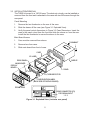
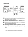
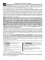
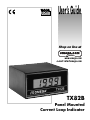
User’s Guide
Shop on line at
omega.com
®
OMEGA®
www.omega.com
e-mail: [email protected]
TX82B
Panel Mounted
Current Loop Indicator
®
®
OMEGAnet® On-Line Service
www.omega.com
Internet e-mail
[email protected]
Servicing North America:
USA:
ISO 9001 Certified
Canada:
One Omega Drive, P.O. Box 4047
Stamford CT 06907-0047
TEL: (203) 359-1660
FAX: (203) 359-7700
e-mail: [email protected]
976 Bergar
Laval (Quebec) H7L 5A1
TEL: (514) 856-6928
FAX: (514) 856-6886
e-mail: [email protected]
For immediate technical or application assistance:
USA and Canada:
Sales Service: 1-800-826-6342 / 1-800-TC-OMEGA®
Customer Service: 1-800-622-2378 / 1-800-622-BEST®
Engineering Service: 1-800-872-9436 / 1-800-USA-WHEN®
Mexico and
Latin America:
TEL: (001)800-TC-OMEGA®
FAX: (001) 203-359-7807
En Español: (001) 203-359-7803
e-mail: [email protected]
Benelux:
Postbus 8034, 1180 LA Amstelveen, The Netherlands
TEL: +31 20 3472121
FAX: +31 20 6434643
Toll Free in Benelux: 0800 0993344
e-mail: [email protected]
Frystatska 184, 733 01 Karviná
TEL: +420 59 6311899
FAX: +420 59 6311114
e-mail: [email protected]
11, rue Jacques Cartier, 78280 Guyancourt
TEL: +33 1 61 37 29 00
FAX: +33 1 30 57 54 27
Toll Free in France: 0800 466 342
e-mail: [email protected]
Daimlerstrasse 26, D-75392 Deckenpfronn, Germany
TEL: +49 7056 9398-0
FAX: +49 7056 9398-29
Toll Free in Germany: 0800 639 7678
e-mail: [email protected]
One Omega Drive
River Bend Technology Centre
Northbank, Irlam Manchester M44 5BD United Kingdom
TEL: +44 161 777 6611
FAX: +44 161 777 6622
Toll Free in England: 0800 488 488
e-mail: [email protected]
Servicing Europe:
Czech Republic:
France:
Germany/Austria:
United Kingdom:
ISO 9002 Certified
TABLE OF CONTENTS
1.0 GENERAL INFORMATION
...........................................1
2.0 SPECIFICATIONS . . . . . . . . . . . . . . . . . . . . . . . . . . . . . . . . . . . . . . . . . . . . . . . . . . 2
2.1 Input . . . . . . . . . . . . . . . . . . . . . . . . . . . . . . . . . . . . . . . . . . . . . . . . . . . . . . . . .2
2.2 Accuracy at 25°C . . . . . . . . . . . . . . . . . . . . . . . . . . . . . . . . . . . . . . . . . . . . . . . . 2
2.3 Analog-To-Digital Conversion . . . . . . . . . . . . . . . . . . . . . . . . . . . . . . . . . . . . . . 2
2.4 Display . . . . . . . . . . . . . . . . . . . . . . . . . . . . . . . . . . . . . . . . . . . . . . . . . . . . . . . . 3
2.5 Environmental . . . . . . . . . . . . . . . . . . . . . . . . . . . . . . . . . . . . . . . . . . . . . . . . . . 3
2.6 Mechanical . . . . . . . . . . . . . . . . . . . . . . . . . . . . . . . . . . . . . . . . . . . . . . . . . . . . 3
3.0 MECHANICAL ASSEMBLY AND INSTALLATION . . . . . . . . . . . . . . . . . . . . . . . . . . . 4
3.1 Safety Considerations . . . . . . . . . . . . . . . . . . . . . . . . . . . . . . . . . . . . . . . . . . . . 4
3.2 Intrinsic Safety Parameters for FM (Factory Mutual) . . . . . . . . . . . . . . . . . . . . . 4
3.3 Installation/Removal . . . . . . . . . . . . . . . . . . . . . . . . . . . . . . . . . . . . . . . . . . . . . 5
4.0 SIGNAL INPUT CONNECTIONS (P3) . . . . . . . . . . . . . . . . . . . . . . . . . . . . . . . . . . . 6
5.0 CONFIGURATION . . . . . . . . . . . . . . . . . . . . . . . . . . . . . . . . . . . . . . . . . . . . . . . . . . 7
5.1 Standard Setup . . . . . . . . . . . . . . . . . . . . . . . . . . . . . . . . . . . . . . . . . . . . . . . . . 7
5.2 Field Configuration Chart . . . . . . . . . . . . . . . . . . . . . . . . . . . . . . . . . . . . . . . . . 7
6.0 CUSTOMER CONFIGURATION AND CALIBRATION . . . . . . . . . . . . . . . . . . . . . . . .9
6.1 Formula . . . . . . . . . . . . . . . . . . . . . . . . . . . . . . . . . . . . . . . . . . . . . . . . . . . . . . . 9
6.2 Configuration Procedures . . . . . . . . . . . . . . . . . . . . . . . . . . . . . . . . . . . . . . . . 10
6.3 Calibration . . . . . . . . . . . . . . . . . . . . . . . . . . . . . . . . . . . . . . . . . . . . . . . . . . . . 10
6.4 Factory-Setup Label . . . . . . . . . . . . . . . . . . . . . . . . . . . . . . . . . . . . . . . . . . . . 10
7.0 WIRING DIAGRAM . . . . . . . . . . . . . . . . . . . . . . . . . . . . . . . . . . . . . . . . . . . . . . . . . .11
ILLUSTRATIONS
Figure 3-1
Figure 3-2
Figure 5-1
Figure 7-1
Exploded View . . . . . . . . . . . . . . . . . . . . . . . . . . . . . . . . . . . . . . . . . . . . . . 5
DIN Case Dimensions . . . . . . . . . . . . . . . . . . . . . . . . . . . . . . . . . . . . . . . . 6
Main Board Jumper Locations . . . . . . . . . . . . . . . . . . . . . . . . . . . . . . . . . . 8
Wiring Diagram for TX82B Usage for FM (Factory Mutual) . . . . . . . . . . . 11
i
UNPACKING INSTRUCTIONS
Remove the Packing List and verify that you have received all equipment,
including the following:
QTY
DESCRIPTION
1
Current Loop Meter Indicator with all applicable connnectors attached.
1
Owner's Manual
1
Factory Setup Label
If you have any questions about the shipment, use the phone number for the
Customer Service Department nearest you.
When you receive the shipment, inspect the container and equipment for signs of
damage. Note any evidence of rough handling in transit. Immediately report any
damage to the shipping agent.
The carrier will not honor damage claims unless all
shipping material is saved for inspection. After
examining and removing contents, save packing
material and carton in the event reshipment is
necessary.
ii
1.0 GENERAL INFORMATION
Model TX82B two-wire current-loop indicator accepts 1-5 mA, 4-20 mA, or 10-50
mA process signals and digitally displays the process variable in percentage or
engineering units of such measurements as pressure, flow, temperature and level.
No separate power supply or power connections are required, since the TX82B
obtains operating power directly from the current loop with a voltage drop of less
than 2.5 V. It can tolerate current overdrives up to 200 mA forward and 1000 mA
reverse.
The compact TX82B circuit is mounted in a black polycarbonate case with the
standard 1/8 DIN panel-mount bezel and a depth of less than 110 mm (4.33 in).
Five 12.7 mm (0.5 in) high liquid crystal 7-segment digits are used to display
±1999 active counts plus one or two dummy right-hand zeros.
The TX82B displays from -1999 to 1999 counts with the option of one or two
dummy right-hand “0” digits. Zero suppression or elevation capability exceeds
full scale. Program jumpers are used to scale the readout for percentage or
engineering-unit display. Both zero and span are fine-tuned with multiturn
potentiometers accessible through the display board, requiring lens removal for
readjustment.
When removed from its case, the TX82B can be programmed with gas-tight
jumpers for three input ranges (1-5, 4-20 or 10-50 mA), four coarse zero ranges,
four decimal-point locations and the dummy right-hand zeros. Two additional
jumpers are provided to reverse the span slope so that increasing the input can
cause a reading decrease; thus a 4-20 mA input can be programmed to produce
a 2000 to -18000 reading when one dummy right-hand zero is also used.
1
2.0 SPECIFICATIONS
2.1 INPUT
Current
1-5 mA, 4-20 mA or 10-50 mA
Protection
200 mA max forward and 1000 mA max
reverse
Voltage Drop
2.5 V max forward and 1.2 V max reverse
Span Range
100 to 2000 counts continuous adjustment
with a multiturn potentiometer
Zero Range
The multiturn zero potentiometer can displace
the displayed reading by ±500 counts from the
center of each of the four overlapping zero
ranges, provided that the resultant is within the
±1999 count display capability.
Span Slope
Positive or Negative
Normal Mode Rejection
at 50/60 Hz
46 dB minimum
2.2 ACCURACY AT 25°C
Maximum error
±0.1% R ±1 count
Zero tempco
±0.1 ct/K typ, ±0.3 ct/K max
Span tempco
±0.005%S/K typ, ±0.015%S/K max
2.3 CONVERSION
Technique
Dual-slope, average value with autozero
correction
Polarity
Determined automatically at the end of input
integration period
Input integration period
100 milliseconds (nominal value)
Reading rate
2.5/second
2
2.4 DISPLAY
Type
7-segment LCD
Color
Black digits with white background
Symbols
-1.8.8.8.0.0, 12.7 mm (0.5 in) height
Polarity
Minus sign
Overrange
Three least-significant digits blank
Extra digits
One or two dummy right-hand zeros,
jumper-selectable
Decimal points
Four positions, jumper-selectable
Lifetime (to 2:1 contrast ratio)
More than 30,000 hours
Temperature derating
2:1 for each 10°C above 60°C
Humidity derating
2:1 for each 10%RH above 60%RH
2.5 ENVIRONMENT
Standard operating temp
0 to 55°C
Extended operating temp option
(conformally coated)
-40 to +85°C
Humidity
To 95% at 40°C
Bezel cover option
Splash-proof
2.6 MECHANICAL
Weight
170 g (6 oz)
Case material
Black polycarbonate, 94V-0 flammability rating
Case size
Bezel (HxWxT)
48 x 96 x 7.67 mm
Depth behind bezel
with mounting hardware
Panel cutout (HxW)
Less than 110 mm
45 x 92 mm
Electrical connections
3-terminal screw clamp connector
Wire size
0.13 mm2 - 2.5 mm2 (AWG 26-14)
3
3.0 MECHANICAL ASSEMBLY AND INSTALLATION
3.1 SAFETY CONSIDERATIONS
To ensure safe operation, follow the guidelines below:
VISUAL INSPECTION: Do not attempt to operate the instrument if damage
is found.
SIGNAL WIRING: Insert the proper plus and minus signal wires into the plug-in
screw-clamp connector terminals marked plus and minus. Ensure that the wires
are securely clamped in the plug-in connector by rotating the screws in the
plug–in connector clockwise but do not exceed a torque of .5 newton-meter
(.37 pound-foot). Then plug the connector firmly into the socket located on the
rear panel of the meter.
RAIN OR MOISTURE: Do not expose the instrument to condensing moisture.
3.2 INTRINSIC SAFETY PARAMETERS FOR FM (FACTORY MUTUAL)
Certificate No. 2Y4A4.AX
V max=12.5 V,
I max=250 mA
Intrinsically Safe for Class I, II and III, Division 1, Groups, A,B,C,D,E,F and G
hazardous locations.
Ci=8.6 µF
Li=0 mH
4
3.3 INSTALLATION/REMOVAL
The TX82B is housed in a 1/8 DIN case. The electronic circuitry can be installed or
removed from the front and is attached to the case with two M4 screws through the
rear panel.
Panel Mounting
1.
Remove the two thumbnuts on the rear of the case.
2.
Slide the sleeve off the case (see Figure 3-1 Exploded View).
3.
Verify the panel cutout dimensions in Figure 3-2 Case Dimensions. Insert the
case in the panel cutout from the front and slide the sleeve on from the rear.
Install the two thumbnuts to secure the sleeve to the case.
Main Board Access:
1.
Case must be removed from sleeve.
2.
Remove lens from case.
3.
Slide main board from front of case.
THUMBNUT
CASE
ID. LABEL
REAR PANEL
SLEEVE
MAIN BOARD
DISPLAY
BOARD
PANEL
THREADED STUD
CONFIGURATION LABEL
(BACK SIDE OF DISPLAY BOARD)
FRONT LENS
J3 B
ELECTROSTATIC RISK
DO NOT RUN OR
CLEAN WITH SOLVENT
REAR CONNECTOR (P3)
FOR SIGNAL INPUT
1 2 3
Figure 3-1 Exploded View (includes rear panel)
5
1.89 [48.0]
3.78 [96.0]
7.9 [0.31] MAX
3.50 [88.9]
CASE
SLEEVE
4.15 [105.4]
TOP VIEW
SIDE VIEW
PANELTHICKNESS:
0.25 [6.4] MAX
0.03 [0.8] MIN
0.06
R [1.5]
4 PLCS
1.772 +.024/-.000
[45.00 +0.61/-0.00]
3.622 +.032/-.000
[92.00 +0.81/-0.00]
PANEL CUT-OUT
NOTES: DIMENSIONS ARE IN INCHES [MILLIMETERS].
Figure 3-2. DIN Case Dimensions
4.0 SIGNAL INPUT CONNECTIONS (P3)
The signal input connections for all meters are made at connector P3 as follows
(see Figure 3-1):
P3 Connection
1
2
3
Signal
Signal Hi
Signal Lo
No Connection
6
5.0 CONFIGURATION
The standard TX82B meter is factory-configured for an input of 4-20 mA to display
00.0 to 100.0. Field configuration for input current range, decimal point location,
dummy right-hand zero digit, coarse zero range selection, and reverse span slope
may be done by relocating internal push-on jumpers and adjusting the span and
zero potentiometers. Refer to Figure 5-1 for the span and zero potentiometers and
internal jumper locations.
5.1 STANDARD SETUP
Unless the customized configuration option is specified, jumpers are factory-installed
at S1-H, S2-C, S1-B, S1-C and the unit is calibrated for 4-20 mA = 00.0 to 100.0.
5.2 FIELD CONFIGURATION CHART
CONFIGURATION
1.5 mA Input
*4-20 mA Input
10-50 mA Input
*Normal Span Slope
Reverse Span Slope
Decimal Point 1.999 (DP1)
Decimal Point 19.99 (DP2)
*Decimal Point 199.9 (DP3)
Decimal Point 1999. (DP4)
Decimal Point 19990. (DP5)
Dummy Right-Hand Zero (DRHZ)
Dummy Right-Hand Zeroes (2DRHZ)
Zero Range -2510 to -1420 (ZR1)
Zero Range -1580 to -420 (ZR2)
*Zero Range -470 to +850 (ZR3)
Zero Range +760 to +2000 (ZR4)
JUMPER INSTALLATION
None
S1-H
S1-J
S1-B, S1-C
S1-A, S1-D
S2-E
S2-D
S2-C
S2-B
S2-F
S2-A
S2-G, S2-H, S2-J, S2-A
S1-G
S1-F
None
S1-E
*Standard factory setup
7
D
F
B
C
J
A
E
S1
G
H
R4
SPAN ADJ.
U2
U3
S1
P3
S2
VR1
ZERO ADJ.
VR2
R30
A
H
J
F
C
B
D
E
G
S2
Figure 5-1 Main Board Jumper Locations
8
6.0 CUSTOMER CONFIGURATION AND CALIBRATION
Use this procedure to determine the configuration of the TX82B customized
setup. The procedure is general; customers can specify any two current inputs
and their corresponding digital readings. Pin-groups are shown in Figure 5-1.
6.1 FORMULA
Base all your calculations on either the 1-5, 4-20 or 10-50 mA range.
1. Determine the lowest input current, I1, which is specified by the customer:
I1 =
mA
2.
Determine the highest input current, I2, which is specified by the customer:
3.
Determine the reading, N1, at input current I1, which is specified by the
customer.
4.
Determine the reading, N2, at input current I2, which is specified by the
customer:
5.
Calculate the Gain, G1:
mA
I2 =
counts
N1 =
N2 =
counts
(N2 - N1)
=
counts per mA
(I2 - I1)
(If G1 is greater than 125, it is out of range for a standard unit.)
G1 =
6.
Calculate the Required Zero Range number, RZR:
7.
Select the Zero Range required from the following chart where the Required
Zero Range number falls between the upper and lower limits of that range:
RZR = N1 - (I1 x G1) =
ZR1 =
ZR2 =
ZR3 =
ZR4 =
ZR =
-2510 to -1420
-1580 to -420
-470 to +850
+760 to +2000
9
6.2 CONFIGURATION PROCEDURES
1.
Remove all push-on jumpers.
2.
For an input current range of 1-5 mA, no jumper is required.
For 4-20 mA input, install a push-on jumper at S1-H.
For 10-50 mA input, install a push-on jumper at S1-J.
3.
If N2 (Section 6.1) is less than N1, reverse the signal polarity by removing
jumpers from S1-B and S1-C and reinstalling jumpers at S1-A and S1-D.
4.
Select the zero range required (ZR1-4) and install the push-on jumper as
indicated in the configuration chart (Section 5.2).
5.
If a decimal point is required (DP1-5), install a push-on jumper as indicated
in the configuration chart (Section 5.2).
6.
If one dummy right-hand zero is required, install jumper at S2-A.
7.
If two dummy right-hand zeros are required, install jumpers at S2-A, S2-G,
S2-H, and S2-J.
6.3 CALIBRATION
1.
Apply an input current (I1) and adjust the zero pot (Z) to read N1.
2.
Apply an input current (I2) and adjust the span pot (S) to read N2.
3.
Repeat steps 1 and 2 as required to set N1 and N2 to within ±1 count.
6.4 FACTORY-SETUP LABEL
The label on the meter shows the factory-configured input and display settings.
If the configuration is changed, use the extra label included with the meter to
indicate the new settings.
10
7.0 WIRING DIAGRAM
HAZARDOUS AREA
MODEL
TX82B
INDICATOR
2
SAFE AREA
3
4
+
-
INTERCONNECTING
CABLES
SHUNT ZENER
DIODE
SAFETY
BARRIER
SAFE AREA
APPARATUS
1
EARTHED BUS BAR
NOTES:
1
Apparatus which is unspecified except that it must not be supplied from nor
contain under normal or abnormal conditions a source of potential with respect to
Earth in excess of 250V R.M.S. or 250V D.C.
2
The following output parameters apply; Vmax=12.5V, Imax=250mA, Ci=8.6uF,
Li=0mH
3
The Interconnecting Cable may be a twin pair, or a pair contained in a type A or
type B multicore cable provided that the peak voltage of any circuit contained
within the multicore does not exceed 60 volts.
4
The capacitance or inductance or inductance to resistance (4/R) ratio of the
Interconnecting Cable must not exceed the values specified for the barrier in use.
5
The electrical circuit in the Hazardous Area must be capable of withstanding
without breakdown an A.C. test voltage of 500V R.M.S. to Earth or frame for one
minute.
Figure 7-1 Wiring Diagram for TX82B Usage for FM (Factory Mutual)
11
WARRANTY/DISCLAIMER
OMEGA ENGINEERING, INC. warrants this unit to be free of defects in materials and workmanship for a
period of 13 months from date of purchase. OMEGA Warranty adds an additional one (1) month grace
period to the normal one (1) year product warranty to cover handling and shipping time. This
ensures that OMEGA’s customers receive maximum coverage on each product.
If the unit should malfunction, it must be returned to the factory for evaluation. OMEGA’s Customer
Service Department will issue an Authorized Return (AR) number immediately upon phone or written
request. Upon examination by OMEGA, if the unit is found to be defective it will be repaired or replaced at
no charge. OMEGA’s WARRANTY does not apply to defects resulting from any action of the purchaser,
including but not limited to mishandling, improper interfacing, operation outside of design limits,
improper repair, or unauthorized modification. This WARRANTY is VOID if the unit shows evidence of
having been tampered with or shows evidence of being damaged as a result of excessive corrosion; or
current, heat, moisture or vibration; improper specification; misapplication; misuse or other operating
conditions outside of OMEGA’s control. Components which wear are not warranted, including but not
limited to contact points, fuses, and triacs.
OMEGA is pleased to offer suggestions on the use of its various products. However,
OMEGA neither assumes responsibility for any omissions or errors nor assumes liability for any
damages that result from the use of its products in accordance with information provided by
OMEGA, either verbal or written. OMEGA warrants only that the parts manufactured by it will be
as specified and free of defects. OMEGA MAKES NO OTHER WARRANTIES OR
REPRESENTATIONS OF ANY KIND WHATSOEVER, EXPRESSED OR IMPLIED, EXCEPT THAT OF
TITLE, AND ALL IMPLIED WARRANTIES INCLUDING ANY WARRANTY OF MERCHANTABILITY
AND FITNESS FOR A PARTICULAR PURPOSE ARE HEREBY DISCLAIMED. LIMITATION OF
LIABILITY: The remedies of purchaser set forth herein are exclusive and the total liability of
OMEGA with respect to this order, whether based on contract, warranty, negligence,
indemnification, strict liability or otherwise, shall not exceed the purchase price of the
component upon which liability is based. In no event shall OMEGA be liable for
consequential, incidental or special damages.
CONDITIONS: Equipment sold by OMEGA is not intended to be used, nor shall it be used: (1) as a “Basic
Component” under 10 CFR 21 (NRC), used in or with any nuclear installation or activity; or (2) in medical
applications or used on humans. Should any Product(s) be used in or with any nuclear installation or
activity, medical application, used on humans, or misused in any way, OMEGA assumes no responsibility
as set forth in our basic WARRANTY/ DISCLAIMER language, and additionally, purchaser will indemnify
OMEGA and hold OMEGA harmless from any liability or damage whatsoever arising out of the use of the
Product(s) in such a manner.
RETURN REQUESTS / INQUIRIES
Direct all warranty and repair requests/inquiries to the OMEGA Customer Service Department. BEFORE
RETURNING ANY PRODUCT(S) TO OMEGA, PURCHASER MUST OBTAIN AN AUTHORIZED RETURN
(AR) NUMBER FROM OMEGA’S CUSTOMER SERVICE DEPARTMENT (IN ORDER TO AVOID
PROCESSING DELAYS). The assigned AR number should then be marked on the outside of the return
package and on any correspondence.
The purchaser is responsible for shipping charges, freight, insurance and proper packaging to prevent
breakage in transit.
FOR WARRANTY RETURNS, please have the
following information available BEFORE
contacting OMEGA:
1. P.O. number under which the product was
PURCHASED,
2. Model and serial number of the product under
warranty, and
3. Repair instructions and/or specific problems
relative to the product.
FOR NON-WARRANTY REPAIRS, consult OMEGA
for current repair charges. Have the following
information available BEFORE contacting OMEGA:
1. P.O. number to cover the COST
of the repair,
2. Model and serial number of product, and
3. Repair instructions and/or specific problems
relative to the product.
OMEGA’s policy is to make running changes, not model changes, whenever an improvement is possible. This affords
our customers the latest in technology and engineering.
OMEGA is a registered trademark of OMEGA ENGINEERING, INC.
© Copyright 2003 OMEGA ENGINEERING, INC. All rights reserved. This document may not be copied, photocopied,
reproduced, translated, or reduced to any electronic medium or machine-readable form, in whole or in part, without prior
written consent of OMEGA ENGINEERING, INC.
Where Do I Find Everything I Need for
Process Measurement and Control?
OMEGA…Of Course!
Shop on line at www.omega.com
TEMPERATURE
Thermocouple, RTD & Thermistor Probes, Connectors, Panels & Assemblies
Wire: Thermocouple, RTD & Thermistor
Calibrators & Ice Point References
Recorders, Controllers & Process Monitors
Infrared Pyrometers
PRESSURE, STRAIN AND FORCE
Transducers & Strain Gauges
Load Cells & Pressure Gauges
Displacement Transducers
Instrumentation & Accessories
FLOW/LEVEL
Rotameters, Gas Mass Flowmeters & Flow Computers
Air Velocity Indicators
Turbine/Paddlewheel Systems
Totalizers & Batch Controllers
pH/CONDUCTIVITY
pH Electrodes, Testers & Accessories
Benchtop/Laboratory Meters
Controllers, Calibrators, Simulators & Pumps
Industrial pH & Conductivity Equipment
DATA ACQUISITION
Data Acquisition & Engineering Software
Communications-Based Acquisition Systems
Plug-in Cards for Apple, IBM & Compatibles
Datalogging Systems
Recorders, Printers & Plotters
HEATERS
Heating Cable
Cartridge & Strip Heaters
Immersion & Band Heaters
Flexible Heaters
Laboratory Heaters
ENVIRONMENTAL
MONITORING AND CONTROL
M1060/0303
Metering & Control Instrumentation
Refractometers
Pumps & Tubing
Air, Soil & Water Monitors
Industrial Water & Wastewater Treatment
pH, Conductivity & Dissolved Oxygen Instruments
10579ML-99 J