1
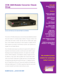
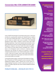
Volume 5, November 2003
Did You Know…
Meridian Integrated Personal
Call Director (MIPCD) Music File:
The current software release on the
MIPCD is 1.5. When the “one number”
is called and the MIPCD begins to
search for the user based on the
“follow me” profile, music is played. At
present the music being played is a
“fixed” program in that it must be used
and no alternate file can be loaded to
the MIPCD. Customized music files
IN THIS ISSUE
Interoperability
• OM5000 ITU CWDM OMX and Finisar OADM
• MLT Interoperability between PP8600 and BayStack Series
Switches
Technology
• Fiber Channel (FC) Basics
Network Management
• Installing Preside Trail Manager from the Hard Disk
Routers / Switches
• PPP/HSSI CRC Size Difference between a Contivity 2600 and
a Backbone Node BLN
• Contivity EF Egress Shaping vs. Interface Shaping
• Passport 8600 “Outloss Packets” Statistic Explained
cannot be used until Release 2 which
is planned to be released in 2Q/04.
The music file that is about 1 minute in
duration will be approximately 1MB in
Wireless LAN
• 802.1x for Wired Networks
• Throughput on Wireless LANs
size.
1
INTEROPERABILITY
OM5000 ITU CWDM OMX and Finisar OADM
The Nortel Networks OM5000 ITU CWDM OMX
provides a superior alternative to the Finisar CWDM
Optical Multiplexer (OMUX). The OM5000 CWDM
OMX is available in a 4-port or an 8-port version, and
provides the following advantage over the Finisar
OMUX’s:
1. Significant reduction in price
2. Lower dB loss (in some cases); hence
longer fiber distance
For point-to-point CWDM designs, the OM5000
CWDM OMX’s can be used to mux/demux up to 8
wavelengths on a single fiber cable. For CWDM ring
implementation where various wavelengths are
dropped at different sites, the OM5000 CWDM OMX
can be used with the Finisar Optical Add-Drop
Multiplexer (OADM).
This configuration was tested thoroughly in Nortel
Networks Core Systems Engineering (CSE) Labs
using the test configuration illustrated below
The test configuration represents a typical small-scale
CWDM network design. The core of the network
consists of two peer Passport 8600’s running SMLT to
the remote sites. Each Passport 8600 in the core
connects to the fiber ring using an 8-port OM5000
CWDM OMX. Site one is serviced by the 1470nm
wavelength, site two is serviced by the 1490nm
wavelength, and site three is serviced by the 1530nm
wavelength. Each of the 3 sites uses a BPS2000
equipped with a dual mini-GBIC MDA. At each of the
sites, the link on the left side of the OADM (which
represents the wavelength that is dropped from the
west side of the ring) provides the connection to Core
Node A, and the link on the right side of the OADM
(which represents the wavelength that is dropped from
the east side of the ring) provides connection to Core
Node B. For optimum resiliency, the sites are
connected to the core using Split-MLT.
In order to test the impact of failing fiber links in the
CWDM core, real-applications; including MPEG-2
video streaming, Web client/host browsing, and Voice
over IP applications were used.
Failure testing included failing and recovering all the
links along the CWDM ring (Link1, Link2, Link3, and
Link4) as illustrated on the network diagram.
Sub-second fail-over was always achieved, both upon
a link failure or a link recovery, and the failure was
fairly transparent to the user applications.
For link budget engineering, the following is an
example and a comparison using the OM5000 CWDM
OMX verses the Finisar CWDM OMUX:
Constants
•
Loss Budget for APD Optics = 24db
•
Finisar OADM Add Loss = 1.2db
•
Finisar OADM Passthrough Loss = 1.5db
•
OM5000 CWDM OMX 4ports Drop Loss = 2.4db
(worst case)
•
OM5000 CWDM OMX 8ports Drop Loss = 3.9db
(worst case)
•
OM5000 CWDM OMX 4ports Add Loss = 2.1db
(worst case)
•
OM5000 CWDM OMX 8ports Add Loss = 3.7db
(worst case)
•
Finisar OMUX Drop Loss = 4db (worst case)
•
Finisar OMUX Add Loss = 3dB(worst case)
•
System Margin = 3db
•
Sigma = 2.4db
•
Attenuation per Kilometer = will depend of the
type of fibers. Fiber characterization should be
performed on fibers span to get the dB per Km
or miles. In some cases, the fiber loss included
the connectors. If the connectors are not
included, an average of .5dB loss per connector
should be counted.
2
Calculations per wavelength
The link budget has to be calculated for every
wavelength. The following should be included:
The two most common protocol mappings for Fiber
Channel are FCP, which is SCSI over FC and FC-SB2, single byte command code set for FICON.
•
FICON comes as an ESCON evolution and is based
on the Fiber Channel Standards. FICON support
started bridging from FICON channels to existing
ESCON Directors and ESCON Control Units,
delivering value using channel consolidation, cable
reduction, increased distance and increased device
address-ability. Since FICON is just another upper
layer protocol using standard Fiber Channel transport,
FICON Directors are highly available Fiber Channel
switches with capabilities that allow in-band
management.
•
•
•
•
Passthrough Nodes = Number of OADM
between Add OADM and OMUX
Passive Loss = OADM Add + OMUX Drop +
(Passthrough Nodes*OADM PT)
Implied Fiber Loss (IFL) = Loss Budget for fiber
span
Passive Loss – Margin (refer to as customer
margin) – Sigma (standard deviation average
loss for the components)
Max Transmission Distance = IFL (see
above)/Attenuation per Kilometer =
MLT Interoperability between PP8600 and
BayStack Series Switches
When configuring Multi Link Trunking on the PP8600
platform, one must remember to use the same media
type (i.e. Single Mode, Multi Mode, 100BaseT, 100FX,
etc.) for all links in that MLT relationship. This is
important to remember when engineering a network
consisting of both PP8600’s and BayStack Series
switches. Baystack switches will allow different media
types in the relationship. Java Device manager will
provide an error messages if differing media types are
specified on the PP8600 during configuration.
The Fibre Channel flow control mechanism is credit
based to ensure there is never any congestion in the
end to end path, unlike IP mechanisms. Within a fibre
channel switch these credits are commonly referred to
as “buffer credits.”
Similar to the OSI model of seven (7) layers, the Fiber
Channel architecture is structured in 4 layers.
FC-4
FC-3
FC-2
TECHNOLOGY
Fiber Channel (FC) Basics
Fiber channel combines the best of channel and
network technologies. Essentially a data pipe, a
channel is a directly attached and well-structured
mechanism designed to transmit data between a host
and a fixed number of peripheral devices. The two
most common channel protocol mappings are SCSI
and ESCON.
A network is designed to be dynamic and redundant; it
must automatically adjust to a changing environment
and support a varying number of nodes. It provides
flexibility in connectivity leading to greater scalability
and provides greater distances than channels. This
gives FC the high speed of channels and the dynamic
connectivity of networks.
Upper layer protocol (ULP) mapping
Services for multiple ports on one node
Frame format, sequence and exchange management,
flow control, CoS, Login/logout, topologies and
segmentation and re-assembly
8B/10B character encoding
FC-1
Signaling, media specifications, RX/TX specifications
FC-0
FC-0 and FC-1 can be compared to the physical layer
of the OSI model, while FC-2 is similar to a portion of
the data link layer. FC-3 is for common services for
devices with multiple ports (i.e. login server, Name
server and alias server and so on) and finally FC-4
defines how upper layer protocols (SCSI) are mapped
to fibre channel similar to the OSI transport layer.
A good source for storage information can be found at
the IBM storage site at http://www.storage.ibm.com/
3
NETWORK MANAGEMENT
Installing Preside Trail Manager from the
Hard Disk
Trail Manager 4.2.4 Service Pack 1 is distributed on
CD-ROM and is typically installed in this format at
customer locations. The user documentation details
the installation procedure (in the Trail Management
4.2 SP1 Administration Guide NTP 450-3101-094)
from CD-ROM. When running the install script the
following line asks for the device type:
Enter the type of device [cdrom (default), tape, 'abort'
to quit]
This appears to imply that Trail must either be
installed from CD-ROM or Tape. While these are the
common sources for the software, in a lab
environment it may be useful to be able to install from
a set of files located on the local or remote hard disk.
Installing from a file can be easily accomplished by
selecting ‘cdrom’ as the option when asked for the
source. The next item that the install script will ask for
is the mount point:
Enter CD-ROM mount point, or
Type 'abort' to quit [/cdrom] :
In this field, instead of entering a CDROM mount
point, enter the directory location where the Trail
Manager files are located (eg. /tmp/tm57bw). The
Trail Manager install script does not distinguish
between this directory location and a cdrom mount
point, so it will proceed to install Trail from this
location providing all relevant files are placed in this
directory (i.e. the directory must appear as a cdrom
would).
ROUTERS / SWITCHES
Click on the HSSI interface
Click ‘Edit Line’
Set the CRC size to ’16 bit’
Click OK
Contivity EF Egress Shaping vs. Interface
Shaping
Contivity V4.8 supports both EF egress shaping and
Interface shaping. Here is a list of comparisons
between the two shaping features:
• They both delay the outgoing packet flow
through egress interface. Non-conforming
traffic is delayed, not dropped.
• They are both disabled by default, and have
to be enabled before functioning, and both
support configurable shaping rate.
• Interface shaping applies to all traffics
regardless of protocols or markings, while EF
egress shaping applies to EF marked packets
only.
• Interface shaping is available on the Ethernet
interface only, while EF egress shaping
applies to Ethernet, T1, HSSI, V35, X21 WAN
interfaces.
• If both shaping features are enabled and
configured on Ethernet interface, whichever
has the smaller shaping rate will control EF
egress shaping rate.
To enable EF egress shaping, in the Main menu >QoS->QoS Interface, select “Enabled” for “Traffic
Conditioning State” to the desired interface. Then
configure the desired shaping rate on “Expedited
Forwarding Shaping Rate” for Egress (Outbound).
Below is a lab demo. Both shaping features are
enabled on public interface, slot 4, Ethernet interface
1. Shaping and MF are disabled on private interface.
PPP/HSSI CRC Size Difference between a
Contivity 2600 and a Backbone Node BLN
In recent testing it was discovered that the default
CRC sizes on a HSSI/PPP link between a Contivity
2600 and Backbone Node are different. The Contivity
HSSI interface defaults to a 16 bit CRC and the BN
HSSI interface defaults to a 32 bit CRC. In order for
the PPP link to come up, one must change the BN’s
HSSI interface to a 16 bit CRC. From Site Manager:
Contivity
FTP
Slot 4,
Ethernet
interface 1
FTP
Disable
Shaping
download large size file
First, setup Public Interface shaping rate = 6M, and
EF shaping rate = 2M. And MF marking is enabled
4
with a rule to mark all IP as EF. Make sure the user
profile has default setting “excess action: Mark”.
prevents successful reassembly of an egress frame.
This can occur for two principal reasons:
¾
¾
An 802.3x PAUSE frame was received on an
Ethernet link, and queued egress traffic depleted
available buffer space while the pause function
timer was counting down or before a 0pause_time PAUSE frame (which would resume
transmission) could be processed.
Egress traffic oversubscribes a port’s capacity,
such as when traffic entering at multiple ports
switches to a single output port, or in the case
where traffic bursts between input ports of high
speed to a port of lower speed.
In these cases, the OctaPID buffers what traffic it can,
and when buffers are full, additional frames must be
tail-dropped, causing the counter to increment.
There are a couple of mitigating considerations when
observing an incrementing Outloss Packets counter.
Download a large size file from the FTP server to the
client. The max FTP speed is about 2Mbps. Why?
Since EF egress shaping rate of 2M is smaller than
the interface shaping rate of 6M, the EF egress
shaping rate governs the FTP speed.
Reconfigure the shaping rates as Interface shaping
rate = 3M, and EF egress shaping rate = 6M.
Download a large size file from the FTP server to the
client. The FTP speed is about 3Mbps, since the
Interface shaping rate of 3M is smaller than the EF
egress shaping rate of 6M.
Passport 8600 “Outloss Packets” Statistic
Explained
A statistic displayed from the Passport 8600 CLI,
labeled “OUTLOSS PACKETS,” is not explained in
the product documentation. To view the display, enter
the command:
# show port stats interface main
The Outloss Packets statistic counts the number of
frames that were dropped by an I/O port’s OctaPID
while the frame was being reassembled for
transmission. The OctaPID reports the statistic as
part of the OctaPID egress queuing function, and
increments when a lack of output buffer space
In the case where traffic is lost due to flow control,
since 802.3x flow control was designed in the mid1990s specifically to make it easier to design and
manufacture input buffered switches, sometimes it
makes more sense to turn off flow control on the
neighboring switch if the neighboring switch has an
output buffer or shared memory design. The
neighboring switch may have more capacity to buffer
traffic than the OctaPID that is discarding traffic due to
receipt of the PAUSE frames. To observe line flow
control frame reception, read the 802.3x interface flow
control frame counters from the same “show port stats
interface main” command. Experiment for best results
with link layer flow control on a case by case basis.
Where egress traffic oversubscribes port capacity,
higher layer protocol flow control mechanisms
sensitive to discards should properly throttle traffic,
and the network system is behaving as designed. At
the network maintenance level no defect should be
inferred, though from a design perspective, the
congestion pattern indicated by Outloss Packets might
be studied if users complain of unsatisfactory service.
The output buffer capacity of an OctaPID is best
utilized in conjunction with DiffServ (QoS). Marked
traffic streams distributed among more of the eight
available hardware queues will better utilize the
5
OctaPID’s buffer space than a single queue used by
unmarked (or uniformly marked) traffic.
including the VLAN Id and the Ethernet port priority
which are dynamically configured on the port.
Outloss Packets counters presently have no MIB
object and cannot be polled using SNMP.
802.1x uses Extensible Authentication Protocol (EAP)
which provides a generic transport mechanism for
support various authentication protocols. Nortel’s
Ethernet Switching products play the role of the EAP
Authenticator and support various EAP types
including TLS, TTLS, MD5, and PEAP. The following
Nortel Products support 802.1x/EAP:
Finally, to clear a possible point of confusion, note that
this OctaPID statistic is different from the MACreported interface statistic for excessive collisions on
half-duplex Ethernet or Fast Ethernet links (displayed
via “show port error collision”). Excessive collisions
(16 successive attempts to transmit using CSMA/CD
on a half duplex Ethernet or Fast Ethernet link all
resulting in collisions) can only increment on a
congested half duplex link, while Outloss Packets can
occur any time congestion causes OctaPID transmit
buffer depletion. Frames dropped due to Excessive
Collisions do not affect the Outloss Packets counter;
although of course Outloss Packets might occur if
enough frames are queued up while others await
transmission on a congested half-duplex link.
For more information on the relationship between
physical port and assigned OctaPID, see “Managing
Platform Operations and Using Diagnostic Tools –
Passport 8000 Series Software Release 3.5,”
Appendix D, “Tap and OctaPID Assignment,” pp.251256. For more information on CLI statistical displays,
see the section “Showing Port Statistics,” starting on
p.195.
For a better understanding of OctaPID QoS and
buffering properties, see “Network Design Guidelines Passport 8000 Series Software Release 3.5
Implementation Notes,” section titled “QoS and
network congestion,” pp.337-342. at Customer
Support Documentation
WIRELESS LAN
802.1x for Wired Networks
The IEEE 802.1x standard “Port Based Network
Access Control” has received a lot of attention for
improving the security of wireless networks. Many
Enterprises are also exploring the use of 802.1x for
their wired networks as well. This would force endusers to authenticate against a database (ex.
RADIUS) before gaining access to the network. If the
user is successfully authenticated the database can
optionally return attributes specific to the user
1.
2.
3.
4.
5.
6.
BayStack 450 – starting with version 4.0
BPS2000 – starting with version 1.1
BayStack 470 – starting with version 2.2
BayStack 425 – will support with BoSS 3.0
BoSS 3.0 supports EAP
Passport 8300 – will support EAP in first
release
7. Passport 8600 – will support EAP in next
release
Throughput on Wireless LANs
In general, when referring to the performance of a
Wireless LAN (WLAN) typically the data rates are
quoted, 11 Mbps for 802.11b and 54 Mbps for
802.11a. However, end-user application throughput is
always lower because of protocol overhead and
additional delays associated with accessing the
shared wireless medium. It is important to make this
distinction as the throughput numbers should be used
when designing WLAN networks.
For each packet that is transmitted the following
factors affect the throughput:
1. Protocol Overhead - Physical Layer Convergence
Procedure (PLCP) and Medium Access Control
(MAC) layer preamble and headers are added to
each packet. The PLCP preamble and header is
always transmitted at the lowest data rate.
2. Inter-Frame Spacing – each WLAN technology
(i.e. 802.11a, b, and g) specifies different values
for spacing between transmitted frames. This is
also dependent on the basic data rate.
3. ACK – transmitting data on WLAN networks is
reliable; thus, for each unicast packet transmitted
an ACKnowledgement must be received before
the next packet is sent.
4. Back-off time – WLAN clients implement a Carrier
Sense Multiple Access Collision Avoidance
(CSMA/CA) mechanism in order to avoid
6
collisions. Once a Client determines that the
channel is clear it will wait a random period of time
before transmitting in order to decrease the
probability that two Clients will transmit at the
same time which would result in a collision.
the AP experiencing minimal interference AP thereby
communicating using the highest basic data rate.
Again, not realistic but understanding the limits of
WLAN performance is useful when designing WLAN
networks.
As a result of these factors the maximum theoretical
throughput for 1500 byte packets in an 802.11a
environment is approximately 31 Mbps and in an
802.11b environment is approximately 6-7 Mbps. The
performance degrades as the packet size gets smaller
so realistically actual throughput is even less. This is
a key point to keep in mind when using Voice or Video
applications on WLANs.
These calculations also assume that there are no
collisions and that each mobile client and is close to
_________________________________________
To receive Engineering Tips and Tricks direct in your email box…
If you are authorized Nortel Networks Channel Partner, you can receive it through our bi-weekly Partner
NewsFlash (PNF). Sign up for access to our password protected website, Partner Information Center, and you will
be automatically subscribed to PNF (note: you may unsubscribe at any time).
If you are an Enterprise customer, you can receive it through our Nortel Networks Update. Subscribe for this
monthly e-newsletter to provide you with the latest updates on Nortel Networks, Products and Solutions, Training
and Certification, Industry News, Events, Promotions, and much more.
This publication will evolve based on your content and information requirements, therefore please feel free to
provide feedback on the design and organization of this publication to: [email protected].
7