1
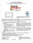
OPERATIONS MANUAL FOR THE MODEL DV23ZC DIRECT VENT ZERO CLEARANCE GAS FIREPLACE APPROVED FOR MOBILE HOME INSTALLATION WARNING: If the following information in this manual is not followed exactly, a fire or explosion may result causing property damage, personal injury, or loss of life. -DO NOT STORE OR USE GASOLINE OR OTHER FLAMMABLE VAPORS AND LIQUIDS IN THE VICINITY OF THIS OR ANY OTHER APPLIANCE. -WHAT TO DO IF YOU SMELL GAS * Do not try to light any appliance. * Do not touch any electrical switch; do not use any phone in your building. * Immediately call your gas supplier from a neighbor's phone. Follow the gas supplier's instructions. * If you cannot reach the gas supplier, call the fire department. -Installation and service must be performed by a qualified installer, service agency, or the gas supplier. -Save this manual for future reference. New Buck Corporation P.O. Box 69 200 Ethan Allen Drive Spruce Pine, NC 28777 Revised Aug/2008 TABLE OF CONTENTS Introduction.......................................................................................................................... 3 Specifications ....................................................................................................................... 3 Installation ........................................................................................................................... 5 Location and Clearance ....................................................................................................... 5 Assembly Steps-Overview................................................................................................... 5 Appliance and Framing Dimensions ................................................................................... 6 Exterior Vent Locations and Restrictions ............................................................................ 9 Minimum-Maximum Vent Length Requirement............................................................... 10 Vent Assembly................................................................................................................... 11 Horizontal Termination ..................................................................................................... 11 Vertical Termination .......................................................................................................... 14 High Altitude ..................................................................................................................... 17 Gas Valve Connection ....................................................................................................... 18 Gas Pressure Checks .......................................................................................................... 18 Operating Instructions ....................................................................................................... 19 Lighting Instructions .......................................................................................................... 19 Shut Off Procedure ........................................................................................................... 21 Log Installation .................................................................................................................. 22 Pilot and Flame .................................................................................................................. 23 Glass Door Installation ...................................................................................................... 23 Wiring Diagrams ............................................................................................................... 24 Accessories or Options ...................................................................................................... 25 Maintenance ....................................................................................................................... 26 General Maintenance ......................................................................................................... 26 Replacement Parts ............................................................................................................. 27 Warranty ............................................................................................................................ 30 1 2 INTRODUCTION This instruction manual will help you obtain a safe, efficient, dependable installation for your appliance and vent system. Please read and understand these instructions before beginning your installation. The model DV23ZC is a sealed combustion, air circulating gas appliance designed for residential and mobile home applications. The appliance must be installed with Dura-Vent GS vent system that is routed to outside atmosphere. It is also listed for bedroom installations. This appliance is designed to operate on natural or propane gas. A millivolt gas control valve with piezo ignition system provides safe, efficient operation. No external electrical power is required to operate the gas valve and burner. 120VAC is required to operate the room air fan. This appliance complies with National Safety Standards and is tested and listed by (ITS) Intertek Testing Services (Warnock Hersey) to ANSI Z21.88-2002 and CSA 2.33-2002 ISA CAN/CGA-2.17-M91Appliance for use at high altitudes. Installation must conform to local codes. In the absence of local codes, installation must comply with the current National Fuel Gas Code, ANSI Z223.1/NFPA54.. (In Canada, installation must comply with the current CAN-1B149 installation code.) Approved for manufactured (Mobile) home installation. For mobile housing, Title 24 CFR, Part 3280 or when such a standard is not applicable, the standard for manufactured home installation, ANSI / NCBS A225.1 or standard for gas equipped recreation vehicles and mobile housing, CSA Z240.4. DO NOT ATTEMPT TO ALTER OR MODIFY THE CONSTRUCTION OF THE APPLIANCE OR ITS COMPONENTS. ANY MODIFICATION OR ALTERATION MAY VOID THE WARRANTY, CERTIFICATION AND LISTINGS OF THIS UNIT. SPECIFICATIONS - MODEL DV23ZC GAS: HIGH FIRE LOW FIRE NAT. 22,000 BTU 14,000 BTU L.P. 22,000 BTU 17,600 BTU GAS INLET PRESSURE: NAT. L.P. MAX. INPUT 10.5" W.C. 14.0" W.C. MIN. INPUT *5.0" W.C. 10.5" W.C. *5.0" W.C. is minimum inlet gas supply pressure for the purpose of input adjustment. MANIFOLD PRESSURE: NAT. 3.5" W.C. L.P. 10.0" W.C. STEADY STATE EFFICIENCY: NATURAL GAS L.P. GAS 77.10% 77.10% FLUE VENT 4" INNER, 6" OUTER; DURA-VENT MODEL GS SAFETY AGA CERTIFIED PILOT GENERATOR, MILLIVOLT SYSTEM ACTIVATED WITH SWITCH OR THERMOSTAT. 3 NOTE: Installation and repair should be performed by a qualified service person. The appliance should be inspected annually by a qualified professional service person. More frequent inspections and cleanings may be required due to excessive lint from carpeting, bedding material, pet hair, etc. It is imperative that the control compartment, burners and circulating air passage ways of the appliance be kept clean. Provide adequate clearances around air openings and adequate accessibility clearance for service and proper operation. Never obstruct the front openings of the appliance. This appliance is designed to operate on natural or propane gas only. The use of other fuels or combination of fuels will degrade the performance of this system. The gas input of this appliance is 22,000 BTU/HR for natural gas and 22,000 BTU/HR for propane gas models. Children and adults should be alerted to the hazards of high surface temperatures and should stay away to avoid burns or clothing ignition. Young children should be carefully supervised when they are in the same room as the appliance. Clothing or other flammable material should not be placed on or near the appliance. Any safety screen or guard removed for servicing this appliance must be replaced prior to operating the appliance. WARNING Do not operate with the glass door removed, cracked, or broken. Replacement of the glass should be done by a licensed or qualified service person. Do not use this appliance if any part has been under water. Immediately call a qualified service technician to inspect the appliance and to replace any parts of the control system and any gas controls which have been under water. Minimum inlet gas pressure is 5" Water Column for natural gas and 10.5" Water Column for propane for the purpose of input adjustment. Maximum inlet gas supply pressure is 10.5" Water Column for natural gas and 14" Water Column for propane. The appliance must be isolated from the gas supply piping system (by closing its individual manual shut-off valve) during any pressure testing of the gas supply piping system at test pressures equal to or less than 1/2 psig (3.5kPa). This appliance and its individual shut-off valve must be disconnected from the gas supply piping system during any pressure testing of that system at pressures in excess of 1/2 psig (3.5kPa). 4 GENERAL INFORMATION LOCATION AND CLEARANCE Make sure your installation location provides adequate combustion and ventilation air. In selecting the location, the aesthetic and functional uses of the appliance are primary concerns. However, vent system routing to the exterior and access to the fuel supply are also important. Consideration should be given to traffic ways, furniture, draperies, etc., due to elevated surface temperatures. The location should also be free of electrical, plumbing or other heating/air conditioning ducts. Be sure to maintain adequate clearances around air openings into combustion chamber. The appliance should be mounted on a fully supported base extending the full width and depth of the unit. The appliance may be located on or near conventional construction materials. However, if installed on combustible materials, such as carpeting, vinyl tile, etc., a metal or wood barrier covering the entire bottom surface must be used. Right and left sides of the unit are determined when standing in front of the unit. Minimum clearance to combustibles: sides and back - 0", floor - 0" , adjacent wall to Front 6". Minimum clearance to combustibles for the vent system is 2" when passing through a wall or chase. ASSEMBLY STEPS—OVERVIEW The typical sequence of installation follows. However, each installation is unique resulting in variations to those described. 1. Construct framing and position the appliance. 2. Route gas supply line and bring in electrical service line to appliance location. 3. Install vent system. 4. Make connection to gas supply and electrical service. 5. Install the log assembly. 6. Install the remote thermostat (optional). 7. Test fire the burner. 8. Install glass panel. 9. Finish enclosure walls and trim. 5 INSTALLATION Figure 1 6 NOTE: * SUPPLIED BY MANUFACTURER INTERIOR HORIZONTAL MINIMUM INSTALLATION NOTE: * NOTE: You may replace or cover this piece of material with a more decorative non-combustible material when the unit is installed. * SUPPLIED BY MANUFACTURER INTERIOR VERTICAL INSTALLATION WITH A MAXIMUM 42' RISE. Figure 2 7 INSTALLATION GENERAL INFORMATION Remove the shipping carton. Make sure the unit is not damaged. Lift the top louver and remove three (3) nuts at the upper left, right, and center of the glass frame. Also, open louver at bottom and remove the three (3) nuts. Set the door aside and protect from inadvertent damage. Retain nuts for reassembly. Next, carefully remove the box of logs inside the appliance and set these aside. 1. Framing - Maintain dimensions for the appliance enclosure as illustrated in Figure 1. 2. Gas Supply - These units are equipped with pipe supply access holes at the right side and right rear facing unit. 3. Position appliance into framing - DO NOT secure with nails at the nailing tabs at top front corners until venting installation is complete. 4. Vent system — NOTE: (The Model No. DV23ZC must be vented using the Simpson-DuraVent Direct Vent Gas 4" inside 6" venting system.) All warranties will be voided and serious fire, health, or other safety hazards may result from any of the following actions: Installation of any damaged components not manufactured or approved by Simpson-DuraVent; failure to meet all clearance requirements; failure to properly twist-lock and seal all components. Each section of Dura-Vent-GS flue system must be properly sealed to prevent the possibility of leakage. This is accomplished by using high temperature silicone sealant. Apply a bead of sealant around the bell section of the inner pipe prior to joining the pieces together. The outer pipe joint may be sealed with metal foil tape or with silicone sealant. WARNING Always maintain required clearances (air spaces) to combustibles to prevent a fire hazard. Do not fill air spaces with insulation. Check installation instructions for minimum clearance requirements between the outer walls of the vent pipe and nearby combustible surfaces. Be sure to check the vent termination clearance requirements from decks, windows, soffits, gas regulators, air supply inlets, and public walkways, as specified in these installation instructions and local building codes. (See page 9.) The gas appliance and vent system must be vented directly to the outside of the building, and never attached to a chimney serving separate solid fuel or gas burning appliances. Each direct vent gas appliance must have its own separate vent system. Common vent systems are prohibited. 5. Remote Wall Switch or Thermostat or Remote Control - This appliance can be switched on or off using one of several devices: 1). Appliance ON/OFF switch, 2) Wall Mounted Remote Wall Switch, 3) Remote Wall Thermostat, or 4) Wireless Remote Control. 6. Connecting gas line — make gas line connections. All codes require a shut-off valve mounted in the supply line. See Figure 15. The flex line method is acceptable in the United States. However, Canadian requirements vary depending upon locality. Installation must be in compliance with local codes. 8 INSTALLATION EXTERIOR VENT LOCATIONS and RESTRICTIONS INSIDE CORNER DETAIL TERMINATION BOX, LOCATION CHART G V A H D E V L V B B C FIXED CLOSED V F N PE O V B B OPENABLE LE AB FIXED CLOSED V B J V A I M V K A A V = VENT TERMINAL A = AIR SUPPLY INLET A. Clearance above grade, veranda, porch, deck, or balcony (*12 inches (30cm) minimum) = AREA WHERE TERMINAL IS NOT PERMITTED H. *Not to be installed above a meter regulator assembly within 3 feet (90 cm) horizontally from the centerline of the regulator. B. Clearance to window or door that may be opened (*12 inches (30cm) minimum.) I. Clearance to service regulator vent outlet (*6 feet (1.8 m) minimum.) C. Clearance to permanently closed window (minimum 12 inches (30 cm)) recommended to prevent condensation on window. J. Clearance to non-mechanical air supply inlet to building or the combustion air inlet to any other appliance (*12 inches (30 cm) minimum.) D. Vertical clearance to ventilated soffit located above the terminal within a horizontal distance of 24 inches (60cm) from the center-line of the terminal (18 inches (46cm) minimum.) K. Clearance to a mechanical air supply inlet (*6 feet (1.8 m) minimum.) L. Clearance above paved sidewalk or a paved driveway located on public property (*7 feet (2.1m) minimum). E. Clearance to unvented soffit (12 inches (30cm) minimum.) F. Clearance to outside corner - 6 inches (15 cm) M. Clearance under veranda, porch, deck, or balcony, (*12 inches (30 cm) minimum). G. Clearance to inside corner - 12 inches (30 cm) A vent shall not terminate directly above a sidewalk or paved driveway that is located between two single family dwellings and serves both dwellings. As specified in “M” above, only permitted if verandas, porches, decks, or balconies are fully open a minimum of two sides beneath the floor. *As specified in CGA B1:19 Installation Codes (1991). NOTE: Local codes or regulations may require different clearances. 9 INSTALLATION NOTE: Direct-Vent (Balanced Flue) appliances are sensitive to vent configurations. Although this appliance may operate in some installations that fall outside this vent requirement chart, we cannot ensure its performance. MINIMUM - MAXIMUM VENT REQUIREMENTS 42' 42' 18' 18' VENTING MUST BE TERMINATED WITHIN SHADED AREA 12' 12' 6' 0' 0' 12' 4' MAX. * MIN. 6' 6' * MINIMUM DISTANCE FROM BEND OF 45° ELBOW TO FACE OF VENT CAP. Figure 3 10 INSTALLATION VENT ASSEMBLY There are two basic types of installations approved with your model DV23ZC appliance. These are: Horizontal termination (See Figure 5) Vertical termination (See Figure 10) When planning your installation, refer to Figure 3 to ensure the length of your vent falls into the limits specified in Figure 3. Also consult page 9, “Exterior Vent Locations and Restrictions” regarding the placement of the vent terminal. HORIZONTAL TERMINATION 1. Set the gas appliance in its desired location. Check to determine if wall studs or roof rafters are in the way when the venting system is attached. If this is the case, you may want to adjust the location of the appliance. 2. Dura-Vent pipe and fittings are designed with special twist-lock connections. Assemble the desired combination of pipe and elbows to the appliance adapter with pipe seams oriented towards the wall or floor, as much out of view as possible. 3. Use only Dura-Vent #985 horizontal termination (wind cap). MALE LOCKING SOCKET FEMALE LOCKING SOCKET Figure 4 Figure 5 NOTE: Twist-lock procedure: Four indentations, located on the female ends of pipes and fittings, are designed to slide straight onto the male ends of adjacent pipes and fittings, by orienting the four pipe indentations so they match and sliding into the four entry slots on the male ends (Figure 4). Push the pipe sections completely together, then twist-lock one section clockwise approximately one-quarter turn, until the two sections are fully locked. Horizontal runs of vent must be supported every three feet. Wall straps are available for this purpose. 11 INSTALLATION HORIZONTAL TERMINATION (continued) NOTE: The horizontal run of vent must be level, or have a 1/4-inch rise for every 1 foot of run toward the termination. Never allow the vent to run downward. This could cause high temperatures and may present the possibility of a fire. A 2" clearance (airspace) MUST be maintained on all vent pipe. 4. With the pipe attached to the appliance adapter, slide the appliance into its correct location, and mark the wall for a 10" x 10" square hole. The center of the square hole should line up with the centerline of the horizontal pipe as shown in Figure 6. Cut and frame the 10" square hole in the exterior wall where the vent will be terminated. If the wall being penetrated is constructed of non-combustible material, e.g., masonry block or concrete, a 9" diameter hole is acceptable. 5. Position the horizontal vent termination in the center of the 10" square hole, and attach to the exterior wall with the four wood screws provided. Before attaching the Vent Termination to the exterior wall, run a bead of non-hardening mastic around its outside edges, so as to make a seal between it and the wall. (See Figure 7.) The arrow on the vent cap should point up. (See Figure 6.) NOTE: Ensure that proper clearances to combustible materials are maintained. Vent Opening Combustible Wall 10” Apply Mastic to All Four Sides (254 mm) 10” (254 mm) Vent Opening Noncombustible Wall Vent Cap 7 1/2” (190mm) Figure 6 12 Wood Screws INSTALLATION HORIZONTAL TERMINATION (continued) Note: The four wood screws provided should be replaced with appropriate fasteners for stucco, brick, concrete, or other types of siding. Venting termination shall not be recessed into a wall or siding. For structures with vinyl siding, a Vinyl Siding Standoff (Part 950) should be installed between the vent cap and the exterior wall. (See Figure 7.) Attach the Vinyl Siding Standoff to the Horizontal Vent Termination. The Vinyl Siding Standoff prevents excessive heat from possibly melting the vinyl siding material. Interior Wall Surface Cut Vinyl Siding Away to Fit Standoff Decorative Wall Thimble Standoff Wood Screws Vent Cap (Horizontal Termination) Nut Wall Thimble Apply Mastic to All Four Sides Bolt Screw Horizontal Vent Pipe Vent Cap Connecting Vent Cap with Horizontal Vent Pipe Installing Vinyl Siding Standoff Figure 7 Figure 8 6. Before connecting the horizontal run of vent pipe to the vent termination, slide the black decorative wall thimble cover over the vent pipe. 7. Slide the appliance and vent assembly toward the wall, carefully inserting the vent pipe into the vent cap assembly. It is important that the vent pipe extend into the vent cap a sufficient distance so as to result in a minimum pipe overlap of 1 1/4". Secure the connection between the vent pipe and the vent cap assembly into the outer wall of the vent pipe. Use two sheet metal screws provided to connect the straps to the Pipe Section. (See Figure 8.) 13 INSTALLATION VERTICAL TERMINATION 1. Set the gas appliance in the desired location. Drop a plumb bob down from the ceiling to the position of the appliance flue exit, and mark the location where the vent will penetrate the ceiling. Drill a small hole at this point. Next, drop a plumb bob from the roof to the hole previously drilled in the ceiling, and mark the spot where the vent will penetrate the roof. Determine if the ceiling joists, roof rafters or other framing will obstruct the venting system. You may wish to relocate the appliance or to offset it as shown in Figure 9, to avoid cutting load bearing members. 2. If an offset is necessary in the attic to avoid obstructions, it is important to support the vent pipe every 3 feet, to avoid excessive stress on the elbows, and possible joint separation. Wall straps are available for this purpose (Figure 9). Vertical Termination Cap Storm Collar Roof Flashing If area above is a not a room, install firestop above framed hole. Wall Strap 45 Deg. Elbow If area above is not a room, install firestop below framed hole. Ceiling Firestop Installing Firestop Offset with Wall Strap and 45 deg Elbows Figure 9 Figure 10 3. Assemble the desired lengths of pipe and elbows necessary to reach from the appliance adapter up through the Round Support Box. Ensure that all pipe and elbow connections are in their fully twist-locked position. (See Figure 10.) 4. Cut a hole in the roof centered on the small drilled hole made in the roof in Step 1. The hole should be of sufficient size to meet the 2" requirements for clearance to combustibles. Continue to assemble lengths of pipe and elbows necessary to reach from the Ceiling Support Box up through the roof line. Galvanized pipe and elbows may be utilized in the attic, as well as above the roof line. The galvanized finish is desirable above the roof line due to its higher corrosion resistance. NOTES: Maintain 2" minimum clearance. To install the Round Support Box/Wall Thimble in a flat ceiling, cut a 10" square hole in the ceiling centered on the hole drilled in step 1 above. Frame the hole as shown in Figure 11. 14 INSTALLATION VERTICAL TERMINATION (continued) 5. Slip the flashing over the Pipe Section(s) protruding through the roof. Secure the base of the Flashing to the roof with roofing nails. Ensure the roofing materials overlap the top edge of the Flashing as shown in Figure 12. Verify that you have at least the minimum clearance to combustibles at the roof line. Figure 12 6. Continue to add Pipe Sections until the height of the Vent Cap meets the minimum building code requirements described in Figure 13. Note that for steep roof pitches, the vent height must be increased. High wind conditions, nearby trees, adjoining roof lines, steep pitched roofs, and other factors can result in poor draft, or down drafting. In these cases, increasing the vent height may solve this problem. ROOF PITCH FLAT TO 7/12 OVER 7/12 TO 8/12 OVER 8/12 TO 9/12 OVER 9/12 TO 10/12 OVER 10/12 TO 11/12 OVER 11/12 TO 12/12 OVER 12/12 TO 14/12 OVER 14/12 TO 16/12 OVER 16/12 TO 18/12 OVER 18/12 TO 20/12 OVER 20/12 TO 21/12 MIN. HEIGHT FEET METERS 1 1.5 2 2.5 3.25 4 5 6 7 7.5 8 0.30 0.46 0.61 0.76 0.99 1.22 1.52 1.83 2.13 2.20 2.44 Figure 13 7. Twist-lock the vent cap. 15 INSTALLATION VERTICAL TERMINATION (continued) NOTES: Use only 45 degree elbows. Use of 90 degree elbows is not allowed in vertical terminations. The 45 degree elbows offer less restriction to the flow of flue gases and intake air. For multi-story vertical installations, a Ceiling Firestop, (Simpson-Dura-Vent, Part 963) is required at the second floor, and any subsequent floors (Figure 14). The opening should be framed to 10" x 10" inside dimensions, in the same manner as shown in Figure 11. Figure 14 Any occupied areas above the first floor, including closets and storage spaces, which the vertical vent passes through, must be enclosed. The enclosure may be framed and sheet rocked with standard construction materials. However, consult the vent manufacturer’s installation instructions for the minimum allowable clearance between the outside of the vent pipe and the combustible surfaces of the enclosure. Do not fill any of the required air spaces with insulation. 16 INSTALLATION HIGH ALTITUDE This unit is approved in Canada for altitude from 0 to 2,000 ft. (0 to 600m) (Can 2.17-M90) with the main burner orifice supplied. For installations above 2,000 feet, follow current CAN/CGA-B149.1 and B149.2. In the USA refer to ANSI Z223.1 — latest edition, Appendix F, for resizing the orifice. At altitudes greater than 2,000 feet it is necessary to match the air and fuel requirements by installing a main burner orifice sized for the elevation that the appliance is installed at by referencing the chart shown below. Be sure to check both front and rear orifice for proper drill size. DRILL SIZING CHART RECOMMENDED SIZE vs. ALTITUDE ALTITUDE 2,000 ft / 600m NATURAL GAS Front Rear # 50 # 59 PROPANE (LPG) Front Rear #1.25mm # 68 3,000 ft / 900m # 51 # 61 # 56 # 69 4,000 ft / 1200m # 51 # 61 # 57 # 69 5,000 ft / 1500m # 51 # 62 # 57 # 69 6,000 ft / 1800m # 52 # 62 # 57 # 70 7,000 ft / 2100m # 52 # 63 # 58 # 70 8,000 ft / 2400m # 52 # 64 # 59 # 70 9,000 ft / 2700m # 53 # 64 # 59 # 71 10,000 ft / 3000m # 53 # 65 # 60 # 71 The above orifice sizing chart should be used as a guide only. Actual orifice size may be different due to venting configuration and actual altitude. . 17 INSTALLATION GAS VALVE CONNECTION The gas control valve is located behind the lower grill. The control valve has a 3/8" NPT threaded inlet port. Secure all joints tightly using appropriate tools and sealing compound. Leak-check the installation with a soapy water solution or electronic leak detector. DO NOT USE OPEN FLAME FOR LEAK TEST. SIT VALVE SUPPLY LINE IN OUT PI L OT 1/2" SHUT-OFF VALVE Figure 15 GAS PRESSURE CHECKS The gas valve is equipped with ports for testing the manifold pressure and inlet pressure. When checking pressures, follow these steps: Check and adjust (if required) the inlet pressure first and then check and adjust (if required) the manifold pressure. 1. With gas valve knob in “OFF” position, use small screw driver to loosen the screw (turn clockwise) inside the pressure port. 2. Slide 1/4" tube over the port and connect other end of tube to pressure gauge/manometer. 3. Start pilot and burner and read pressure. 4. When finished, shut burner and pilot off, remove tube, tighten screw inside pressure port, and carefully check for leaks. NEVER increase gas pressure beyond listed limits. 18 OPERATION OPERATING INSTRUCTIONS Before operating this appliance, proceed through the following checklist. 1. Read and understand these instructions before operating this appliance. 2. Check that there are no gas leaks. If you smell gas do not attempt to light this appliance. 3. Verify that log placement is correct. LIGHTING INSTRUCTIONS SIT-MILLIVOLT VALVE FOR YOUR SAFETY READ BEFORE LIGHTING WARNING: If you do not follow these instructions exactly, a fire or explosion may result causing property damage, personal injury, or loss of life. A. This appliance has a pilot which must be lighted by hand. When lighting the pilot follow these instructions exactly. B. BEFORE LIGHTING smell all around the appliance area for gas. Be sure to smell next to the floor because some gas is heavier than air and will settle to the floor. WHAT TO DO IF YOU SMELL GAS: * Do not try to light any appliance. * Do not touch any electric switch; do not use any phone in your building. * Immediately call your gas supplier from a neighbor’s phone. Follow the gas supplier’s instructions. * If you cannot reach your gas supplier, call the fire department. C. Use only your hand to push in or turn the gas control knob. Never use tools. If the knob will not push in or turn by hand, don’t try to repair it. Call a qualified service technician. Force or attempted repair may result in a fire or explosion. D. Do not use this appliance if any or part of it has been under water. Immediately call a qualified service technician to inspect the appliance and to replace any part of the control system and any gas control which has been under water. 19 LIGHTING INSTRUCTIONS 1. STOP! Read the safety information on page 19. 2. Make sure manual shutoff valve is fully open. 3. Turn off all electrical power to the appliance. Open access door. ¬ 4. Turn control knob clockwise to the “OFF” position. CONTROL KNOB IN OUT PI L OT Figure 16 5. Wait five (5) minutes to clear out any gas. Then smell for gas, including near the floor. If you smell gas, STOP and follow “B” in the safety information on page 19! If you don’t smell gas, go to the next step. NOTE: Pilot is located between the first and second burner. Figure 17 6. Turn control knob counterclockwise « to the “PILOT” position. Press in control knob for fifteen (15) seconds. NOTE: You may be running this heater for the first time after hooking up the gas supply. If so, the control knob may need to be pressed in for thirty (30) seconds. This will allow air to bleed from the gas system. 7. With control knob pressed in, push down and release ignitor button. This will light the pilot. If needed, keep repeating this step until pilot lights. If pilot does not light with piezo, light by hand with a match. 8. Keep control knob pressed in for one (1) minute after lighting pilot. After one (1) minute, release control knob. * If knob does not pop up when released, stop and immediately call your service technician or gas supplier. *If the pilot will not stay lit after several tries, turn the gas control knob to the “OFF” position and call your service technician or gas supplier. 20 NOTE: IF pilot goes out, repeat steps 4 through 10. Wait five (5) minutes before attempting to light pilot again. to “ON” position. 9. Turn control knob counterclockwise « 10. If using unit without wall thermostat place “Auto/Off/Manual” switch into the “Manual” position. If using wall thermostat place “Auto/Off/Manual” Switch into the “Auto” position and place thermostat to a setting higher than the room temperature. 11. Close access panel door. 12. Turn all electrical power on. 13. Your heater is equipped with a “HI/LO” control. Turn clockwise ¬for “Low” and counterclockwise « for “High”. TO TURN OFF GAS TO APPLIANCE SHUTTING OFF UNIT 1. Turn control knob clockwise ¬ to the “OFF” position. 2. Turn off all electric power to the appliance if service is to be performed. SHUTTING OFF BURNER ONLY (Pilot stays lit.) 1. Turn control knob clockwise ¬ to the “PILOT” position. CAUTION: HOT while in operation. Do Not Touch. Keep children, clothing, furniture, gasoline, and other liquids having flammable vapors away. CAUTION: DO NOT TRY TO ADJUST HEATING LEVELS BY USING THE MANUAL SHUT-OFF VALVE. WARNING Improper installation, adjustment, alteration, service or maintenance can cause property damage, personal injury, or loss of life. Refer to owner’s operation manual provided with this appliance. Installation and service must be performed by a qualified installer, service agency, or the gas supplier. IMPORTANT: Always operate the appliance at the completely “ON” or the completely “OFF” positions. Never use the heater at a setting between these positions as this can result in improper combustion and excessive carbon monoxide emissions. Keep burner and control compartment clean. See “General Maintenance” instructions on page 26. 21 Tabs shown unfolded LOG INSTALLATION 1. You must first unfold the left and right log support tabs. These tabs are folded down for shipping and must be unfolded before the rear log is put into place. 2. Place the rear log #1 on the back side of the burner base, flat side toward the rear of the firebox. 3. Take the middle log #2, Grasp it by both ends with ember burn out facing you. Position it between the front and rear burner in the middle of the burner supports. 4. 4 5 Center the front log #3 between the middle log and the front of the burner base. 5. Place the top right log #4 over the pin in the middle log with the branch end resting in the notch of the rear log toward the rear of the unit. 1 6. 5. Place the left top log #5 in the notch on the top left of rear log and the other end in the notch on top left of the middle log. 2 7. You may spread the lava rock (provided with unit) over the rest of the inner bottom. NOTE: IF NECESSARY YOU MAY ADJUST THE REAR 3 TOP LOGS TO THE LEFT OR RIGHT TO ENSURE THE FLAME IS NOT IMPINGING ON THE LOGS. 8. Light the pilot and cycle main burner to ensure that the flame smoothly ignites each burner. It may also be necessary to install logs and glass before the final pilot lighting. NOTE: LOGS MAY PRODUCE STRONG ODOR ON INITIAL CONTACT WITH FLAME. THIS WILL DISSIPATE AFTER APPROXIMATELY ONE HOUR OF CONTINUOUS BURNING. Figure 18 22 OPERATION PILOT AND FLAME Your appliance is equipped with a standing pilot to ensure proper burner ignition. It is visible by looking over the top of the middle log 6" from the right side. While igniting, the flame should impinge on the lighting port tube between the rear and middle burner, which ignites the front and rear burner. Figure 19 When burning, the flame on the middle log should be primarily blue, about 1" to 2" tall and causing a glowing effect on the face of the middle log. The rear flame should be 4" to 5" above the top of the rear log. GLASS DOOR INSTALLATION Install the glass door on your appliance by placing the door brackets over the studs on the stove: three at the top and three at the bottom. Simply tighten nut on each. Do not abuse door, i.e. drop or slam it. When the glass door has been removed for cleaning or service, carefully store it in a safe place. If the door should become broken use caution when removing the broken glass from the frame. WARNING Do not operate appliance with the glass front removed, cracked, or broken. Replacement of the glass should be done by a licensed or qualified service person. WARNING Never operate your appliance with broken glass. Never replace the glass with any material other than glass supplied by your dealer. Replace broken or damaged door/ frame assembly with a new assembly from your dealer. When cleaning the glass, do not use abrasive type cleaners. Use only soap and water. Never clean the glass when hot! 23 OPTIONAL ROOM AIR BLOWER WIRING DIAGRAM Figure 20 CAUTION: LABEL ALL WIRES PRIOR TO DISCONNECTING WHEN SERVICING CONTROLS. WIRING ERRORS CAN CAUSE IMPROPER AND DANGEROUS OPERATION. VERIFY PROPER OPERATION AFTER SERVICING. THE APPLIANCE, WHEN INSTALLED, MUST BE ELECTRICALLY GROUNDED IN ACCORDANCE WITH LOCAL CODES, OR IN THE ABSENCE OF LOCAL CODES, WITH THE NATIONAL ELECTRICAL CODE, ANSI/NFPA70 OR THE CANADIAN ELECTRICAL CODE CSA C22.1. . 24 ACCESSORIES OR OPTIONS This unit is equipped with a millivolt system which enables you to choose from many of the convenient options available. 1. Remote control with built in room thermometer. 2. Wall Switch. 3. Wall Thermostat. PILOT VALVE OUT L OT PIEZO Figure 21 25 PI ROCKER SWITCH IN REMOTE CONTROL EYE MAINTENANCE GENERAL MAINTENANCE Annual maintenance of the unit is required. We recommend that the following procedures be performed each year by your fireplace dealer. Clean all lint and dust build-up around the control valve and air shutter of the venturi. Inspect and clean with a vacuum cleaner around the venturi for any spider webs or lint accumulation. Remove logs and coals, and clean away any foreign matter (excessive lint from carpeting, bedding material, pet hair, household dust, etc.) on the burner and burner base. Inspect and clean the pilot and the underside of the logs for any carbon deposits. Inspect and clean the burner ports by vacuuming top of burner. Make sure hot air outlet grills are free from lint and other obstructions. Never block or obstruct grill openings. Check condition of door gasket. Gaskets must be tight. Replace if necessary. Be sure the vent termination is open and free of blockage, and has not been damaged. The vent termination should be checked annually by a qualified agency. Before reinstalling door assembly, check the operation of the pilot and cycle the burner per the “LIGHTING INSTRUCTIONS” on Page 19. NOTE: The appliance area should be kept clean and free from combustible materials, gasoline, and other flammable vapors and liquids. NOTE: Any safety screen or guard removed for servicing or maintenance must be replaced prior to operating the heater. The flow of combustion and ventilation air should not be obstructed. The viewing glass should be cleaned periodically. Exterior glass may be cleaned with cleaner as desired. Interior glass - use soap and water. 26 SERVICING Repair and replacement work should only be done by a qualified service person. Always shut off the gas supply and make sure that heater is cool before beginning any service operation. Always check for gas leaks after servicing. REPLACEMENT PARTS A parts list with exploded view follows. Always include correct name, part number, and model number of the heater when ordering service parts. KEY# PART DESCRIPTION PART NUMBER 1. S.I.T. PILOT (L.P.) ASSEMBLY PE 199615 1. S.I.T. PILOT (NAT) ASSEMBLY PE 199616 2. GENERATOR PE 240002 3. 1/8" PILOT TUBE MF 1812 ALMTUB 4. GENERATOR WIRE 5. 18" “H” BURNER POH-BURN001 6. ORIFICES NAT. SIZE L.P. SIZE REAR #44 REAR 1.25mm PO 50 & 125 MVORF FRONT #56 FRONT #68 PO 59 & 68 MVORF 7. 3/8" COMPRESSION NUT W/ SLEEVE PH 616 & PH 606 8. 3/8" FLEXIBLE BURNER SUPPLY TUBE 1 piece 6" PO T6-06 2 piece 12" PO T6-12 9. 12" SWITCH WIRES PE 12JUMPER 10. CARLING SWITCH (AUTO/OFF/MANUAL) PE RC211RB 11. PIEZO STRIKER PE 124461 12. S.I.T. 24" IGNITOR WIRE PE 028515 13. COMPRESSION FITTING (TEE) PH 64A-66 14. THERMO-COUPLE PE 290136 15. MANIFOLD ELBOW 90 DEG. PH 69A-6C 16. 820 S.I.T. MV. VALVE 17. 18. 19. 27 LP - PE 820633 NAT - PE 820634 REPLACEMENT PARTS Figure 22 16 28 ADDITIONAL REPLACEMENT PARTS PART DESCRIPTION PART NUMBER *MOTOR *RHEOSTAT *RHEOSTAT KNOB *THERMOSTAT 140 DEG. *THERMOSTAT WIRES FRONT LOUVER ASSEMBLY TOP & BOTTOM DOOR GLASS DOOR GLASS GASKET TAD POLE (W/ADHESIVE) 5 PIECE LOG SET REAR LOG MIDDLE LOG FRONT LOG RIGHT TOP LOG LEFT TOP LOG RELEASE DOOR GASKET BURNER BASE GASKET 1/8"THICK FLUE ADAPTOR GASKET 1/8" THICK * OPTIONAL 29 PE SBR084 PE BC204 PE BC204A PE 400130 PE 30JUMPER PO DV23FG PG DV2341 RP GT716B11 PO23DVLOG #1 #2 #3 #4 #5 PO DV2382 PO DV2386 PO DV2380 WARRANTY LIMITED FOUR YEAR WARRANTY FOR THE BUCK STOVE AND RELATED PRODUCTS PLEASE READ THIS WARRANTY CAREFULLY This warranty covers your new heating unit, so long as it is owned by the original purchaser, including optional and standard accessories purchased at the same time, subject to terms, limitations, and conditions herein set out.To make a claim under this warranty the Bill of Sale or Cancelled check must be presented. This warranty will not cover any damage and/or failure caused by abuse or improper installation of the products covered. WARRANTY For a five year period from the date of purchase, as long as the heater is owned by the original purchaser, NBC will repair or replace, at its option, any part defective in materials or workmanship, with the exception of: optional and standard accessories, glass, gaskets and all parts not permanently attached to the heating unit. Parts not permanently attached to the heating unit are defined as those items designed to be removed from the stove, including those removable with common hand tools. The cost of parts only are included. The customer pays any labor or transportation charges required. Electrical motors, wiring, switches, gas components and all parts not permanently attached.are warranted for one (1) year from date of purchase. Customer pays any transportation charges. PROCEDURE Should you feel that your heater is defective, you should contact any NBC dealer for the name of your nearest authorized heater service representative, who will instruct you on the proper procedure. CONDITIONS AND EXCLUSIONS (A) Replacement of parts may be in the form of new or fully reconditioned parts, at NBC's option. (B) There are no other warranties express or implied including warranties or Merchantability, Fitness for Purpose, or Otherwise except those warranties expressly stated herein. (C) NBC is not liable for indirect, incidental, or consequential damages in connection with the use of the product including any cost or expense of providing substitute equipment or service during periods of malfunction or non-use. Some states do not allow the exclusion of incidental or consequential damages, so the above exclusion may not apply to you. 30 (D) All warranty repairs under this warranty must be performed by an authorized Buck Stove service representative. Repairs or attempted repairs by anyone other than an authorized service representative are not covered under this warranty. In addition, these unauthorized repairs may result in additional malfunctions, the correction of which is not covered by warranty. OTHER RIGHTS This warranty gives you specific legal rights, and you may also have other rights, which vary from state to state. 31