1
a
SERIMUX® Series
SERIMUX-TERM-CS-16/8
Terminal Converter with
Console Switch
Installation and Operation Manual
MAN102 Rev Date 8/19/2008
TRADEMARK
SERIMUX is a registered trademark of Network Technologies Inc in the U.S. and other countries.
COPYRIGHT
Copyright © 2003, 2008 by Network Technologies Inc. All rights reserved. No part of this publication may be reproduced, stored
in a retrieval system, or transmitted, in any form or by any means, electronic, mechanical, photocopying, recording, or otherwise,
without the prior written consent of Network Technologies Inc, 1275 Danner Drive, Aurora, Ohio 44202.
CHANGES
The material in this guide is for information only and is subject to change without notice. Network Technologies Inc reserves the
right to make changes in the product design without reservation and without notification to its users.
i
TABLE OF CONTENTS
INTRODUCTION............................................................................................................................................................. 1
Terminal Converter ...................................................................................................................................................... 1
Console Switch ............................................................................................................................................................ 2
MATERIALS.................................................................................................................................................................... 3
FEATURES AND FUNCTIONS ...................................................................................................................................... 4
1. INSTALLATION .......................................................................................................................................................... 5
1.1 Rack Mounting Instructions ................................................................................................................................... 5
1.2 TERMINAL vs. SERIMUX Cable Connections...................................................................................................... 6
1.3 Connect Devices, Hosts, and Power ..................................................................................................................... 6
1.4 Connect the SERIMUX and TERMINAL to a Network ......................................................................................... 7
1.5 Connect the Monitor and Keyboard....................................................................................................................... 7
1.6 Power Up The SERIMUX-TERM-CS-16 ............................................................................................................... 7
2. GETTING STARTED .................................................................................................................................................. 8
2.1 Setup The TERMINAL ........................................................................................................................................... 8
2.1.1 Entering TERMINAL Setup.............................................................................................................................. 8
2.1.2 Setup Directory ................................................................................................................................................ 8
2.1.3 Changing The TERMINAL Operating Parameters .......................................................................................... 8
F2- Genrl SETUP Menu ........................................................................................................................................ 9
F4- Comm SETUP Menu....................................................................................................................................... 9
2.1.4 Saving and Exiting Setup................................................................................................................................. 9
2.2 Connect to the SERIMUX...................................................................................................................................... 9
3. USING THE SERIMUX CONSOLE SWITCH ........................................................................................................... 11
3.1 Administrator Controls ........................................................................................................................................ 12
3.1.1 Login as the administrator ............................................................................................................................. 12
3.1.2 Port List.......................................................................................................................................................... 13
3.1.3 Port Settings .................................................................................................................................................. 14
3.1.3.1 Port serial settings ................................................................................................................................... 16
3.1.3.2 Modem settings ....................................................................................................................................... 18
3.1.3.3 Port data buffer........................................................................................................................................ 19
3.1.3.4 Clear Port data buffer .............................................................................................................................. 19
3.1.4 User List......................................................................................................................................................... 20
3.1.5 User Settings ................................................................................................................................................. 21
3.1.5.1 Port access.............................................................................................................................................. 22
3.1.5.2 Copy User Settings.................................................................................................................................. 22
3.1.6 Advanced Settings......................................................................................................................................... 23
3.1.6.1 Change administrator password.............................................................................................................. 23
3.1.6.2 Firmware.................................................................................................................................................. 24
3.2. User Controls...................................................................................................................................................... 26
3.2.1 User "Accessible host list" screen ................................................................................................................. 26
3.2.2 User main menu ............................................................................................................................................ 27
3.2.3 Port List screen.............................................................................................................................................. 28
3.2.4 User Terse mode ........................................................................................................................................... 29
3.2.4.1 Terse mode commands........................................................................................................................... 29
3.2.5 System Reset button ..................................................................................................................................... 30
3.3 Firmware Upgrade ............................................................................................................................................... 31
KEYPAD CONTROL..................................................................................................................................................... 33
Functions of the Keypad ............................................................................................................................................ 33
Login the administrator ........................................................................................................................................... 33
Disconnect the administrator or a user with administrative privileges.................................................................... 34
Login a user to the administrator main menu ......................................................................................................... 34
Login user to a port................................................................................................................................................. 34
Login user to a port and connect the user port to a host port................................................................................. 35
Disconnect and logout a user ................................................................................................................................. 35
Connect 2 host ports............................................................................................................................................... 35
ii
Disconnect 2 ports .................................................................................................................................................. 36
Attach or detach a modem...................................................................................................................................... 36
Reset SERIMUX Console Switch to default settings................................................................................................. 36
4. USING THE TERMINAL ........................................................................................................................................... 37
4.1 How To Setup The TERMINAL ........................................................................................................................... 37
4.1.1 Entering TERMINAL Setup............................................................................................................................ 37
4.1.2 Saving and Exiting Setup............................................................................................................................... 37
4.1.3 Setup Directory .............................................................................................................................................. 37
4.2 Changing The TERMINAL Operating Parameters .............................................................................................. 38
F1- Disp SETUP Menu .......................................................................................................................................... 38
F2- Genrl SETUP Menu.......................................................................................................................................... 38
F3- Keybd SETUP Menu ........................................................................................................................................ 39
F4- Comm SETUP Menu........................................................................................................................................ 39
F5- Misc SETUP Menu ........................................................................................................................................... 40
F6-Tabs SET-UP Menu .......................................................................................................................................... 40
F7- FKeys SET-UP Definition Setup Menu ............................................................................................................ 40
F8- Ansbk SET-UP Menu ....................................................................................................................................... 41
F9- Lan Setup Menu ............................................................................................................................................... 41
F10- Colr1 Set-up Menu ......................................................................................................................................... 41
F11- Colr2 Set-up Menu ......................................................................................................................................... 42
4.3 Local Keyboard Commands ................................................................................................................................ 45
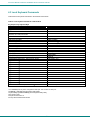
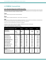
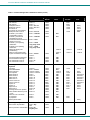
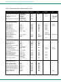
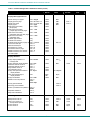
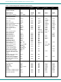
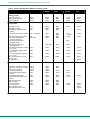
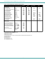
4.4 TERMINAL Command Guide .............................................................................................................................. 46
4.4.1 Commands Supported in ASCII Personalities............................................................................................... 46
4.4.2 Variable Values for Table 8 Commands........................................................................................................ 53
4.5 ANSI Command Guide ....................................................................................................................................... 57
4.5.1 VT100, VT220 and Console ANSI Command Guide .................................................................................... 57
4.5.2 VT52 Command Guide .................................................................................................................................. 64
4.6 Using Printer Server via Ethernet Connection..................................................................................................... 65
4.6.1 Basic Setup.................................................................................................................................................... 65
4.6.2 Setup for LPD ................................................................................................................................................ 66
4.6.3 LPD printing ................................................................................................................................................... 67
4.6.4 Setup for TFTP .............................................................................................................................................. 67
4.6.5 TFTP Printing................................................................................................................................................. 67
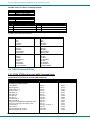
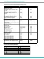
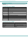
5. HARDWARE INFORMATION................................................................................................................................... 68
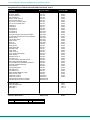
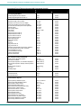
5.1 Hardware Specifications: TERMINAL.................................................................................................................. 68
5.2 Hardware Specifications: SERIMUX ................................................................................................................... 68
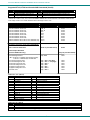
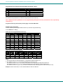
5.3 CPU-to-RACKMUX Ethernet Crossover Cable ................................................................................................... 69
5.4 Serial Port Cabling............................................................................................................................................... 69
5.5 Serial Port Pinouts ............................................................................................................................................... 69
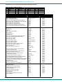
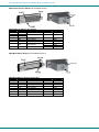
5.6 Cable Adapters .................................................................................................................................................... 70
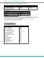
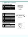
5.7 TERMINAL Connector Pin Assignments ............................................................................................................. 72
INDEX............................................................................................................................................................................ 74
WARRANTY INFORMATION ....................................................................................................................................... 74
iii
TABLE OF FIGURES
Figure 1- Mount Switch in a Rack ...................................................................................................................................................... 5
Figure 2- Distinction of connections between TERMINAL and SERIMUX ......................................................................................... 6
Figure 3- Connect serial devices, printer, and power cord................................................................................................................. 6
Figure 4- Connect to a Local Area Network (LAN)............................................................................................................................. 7
Figure 5- Connect User's Monitor and Keyboard .............................................................................................................................. 7
Figure 6- Fields in the Setup menu display which function keys to press for submenus ................................................................... 8
Figure 7- Startup- Accessible host list ............................................................................................................................................. 10
Figure 8- Administrator main menu.................................................................................................................................................. 12
Figure 9- The Port list displays the status of all ports ...................................................................................................................... 13
Figure 10- The Port settings menu .................................................................................................................................................. 14
Figure 11- Control Codes for in-band disconnect sequence ............................................................................................................ 15
Figure 12- Port serial settings menu ................................................................................................................................................ 16
Figure 13- Modem settings menu .................................................................................................................................................... 18
Figure 14- Port data buffer............................................................................................................................................................... 19
Figure 15- User List ......................................................................................................................................................................... 20
Figure 16- User settings menu......................................................................................................................................................... 21
Figure 17- Port access list for User 01............................................................................................................................................. 22
Figure 18- Administrator's Advanced settings menu........................................................................................................................ 23
Figure 19- Firmware menu............................................................................................................................................................... 24
Figure 20- The SERIMUX is waiting to save its firmware................................................................................................................. 25
Figure 21- A user with limited host port access ............................................................................................................................... 26
Figure 22- User main menu ............................................................................................................................................................. 27
Figure 23- A limited user accessible Port list ................................................................................................................................... 28
Figure 24- User port in Terse mode ................................................................................................................................................. 29
Figure 25- Location of Restore Defaults button ............................................................................................................................... 30
Figure 26- Firmware upload window ................................................................................................................................................ 31
Figure 27- Type "AT" to auto-detect baud rate ................................................................................................................................ 31
Figure 28- Last confirmation before firmware update ...................................................................................................................... 32
Figure 29- File transfer in progress .................................................................................................................................................. 32
Figure 30- Keypad and LEDs........................................................................................................................................................... 33
Figure 31- Fields in the Setup menu display which function keys to press for submenus ............................................................... 37
List of Tables
Table 1- Main Setup Menu (F12) Exit Functions................................................................................................................................ 9
Table 2- Main Setup Menu (F12) Exit Functions.............................................................................................................................. 37
Table 3- Programmable Keys .......................................................................................................................................................... 41
Table 4- Color Setup Menu.............................................................................................................................................................. 42
Table 5- Color Palettes .................................................................................................................................................................... 43
Table 6- Local Keyboard Commands in Native Mode...................................................................................................................... 45
Table 7- Commands Supported in ASCII Personalities ................................................................................................................... 46
Table 8- VT52 Mode Escape Sequences ........................................................................................................................................ 64
iv
NTI RACK MOUNT CONSOLE TERMINAL WITH CONSOLE SWITCH
INTRODUCTION
The SERIMUX-TERM-CS-x (x=8 or 16) combines a 8 or 16 port Console Switch (SERIMUX) and a VT100/ANSI Terminal
Converter (TERMINAL) in a single package controlled by a PS/2 keyboard and VGA monitor. The Console Switch uses menudriven integrated software. The SERIMUX-TERM-CS-16 can control of up to 16 serial devices including servers, switches,
routers, and telecom gear. Additional control methods include front panel keypad, LAN or dial-up modem connections. It enables
unlimited access to remote network management, providing optimum system performance and availability.
Terminal Converter
The Terminal Converter (TERMINAL) is easy to install and configure for either of the following communication modes:
¾
RS232 Terminal (using an RS-232 port for serial console connection). Use this configuration of the Console Terminal with
the Console Switch to control multiple servers.
¾
Telnet Terminal (using an RJ45 10/100 Base-T network port for Ethernet telnet console connection). The Ethernet
connection can be used with any 10/100Mbps-compatible Ethernet host adapter, but is most suited for use with SUN RSC
(Remote System Control) Ethernet ports, since these provide the same functionality as serial (ttya) console ports. This
connection supports up to 12 telnet sessions to different servers. The state of each server session is preserved by the
terminal. Terminal sessions can be switched via hot-keys. When using the Ethernet telnet connection, the Terminal Drawer
can be connected to multiple servers via an Ethernet switch. However, it is advisable that the network used to connect the
server consoles remains private for security reasons.
Note: Both RS232 serial and Ethernet telnet connections cannot be active at the same time.
The TERMINAL is a general purpose character terminal converter offering full transaction capabilities and is largely pre-configured
for most applications. It was designed in conjunction with SUN Microsystems to ensure flawless compatibility with all SUN servers.
Features
•
High-quality metal construction (ideal for most industrial and commercial settings)
•
Supports RSC capabilities.
• Supports parallel and RS232 serial printers
• Printer server capability.
• Converts the RS232 port of a serial device to PS/2 keyboard and VGA ports so the device can be operated by an NTI
KVM switch.
• ASCII text is displayed on the VGA monitor.
• Supports color display functions in 80 and 132 column mode.
• 1RU rackmount case is standard.
•
Connects to 10BaseT Ethernet port
Multiple RS-232 Emulations:
•
•
•
•
•
ADDS A2
PC TERM
PCG Alpha
Console ANSI
TVI910+
•
•
•
•
•
•
•
•
•
TV1925
VT52
VT100
VT220
WY-50+
1
WY-60
WY-100
WY-120
WY-325
NTI RACK MOUNT CONSOLE TERMINAL WITH CONSOLE SWITCH
Console Switch
The Console Switch (SERIMUX) includes a text-based menu for easy connection management for administrators. Using a
terminal emulator the menu provides a quick means for user serial connection changes and device control.
The Console Switch (SERIMUX) is a serial port router that allows links (or connections) between multiple pairs of RS-232
asynchronous serial ports. The main purpose of the switch is to enable users to manage several serial devices from local or
remote locations (using external modems). Devices include routers, DSU's, servers, switches or any other equipment allowing
serial operation using RS232 interface. Users can work locally (using the integral TERMINAL) or from remote locations.
Each SERIMUX port has to be configured for serial communication (baud rate, parity, etc) within the specifications of the attached
serial device, but the configurations of the two devices linked by the SERIMUX do not need to match. Various parameters
(communication speed, hardware and/or software flow control, timeout, etc) can be selected for each SERIMUX port. Devices
may be either locally connected or connected through attached modems.
Each SERIMUX port can be configured as either a host or user port. Serial hosts (such as servers, switches etc.) are connected to
host ports, while serial user devices (such as a terminal or serial console) are connected to user ports.
The SERIMUX Console Switch supports two operator levels: user and administrator. Users login at user ports and connect to
serial devices attached at host ports. The administrator (logged in at any user port) and users with administrative privileges can
connect to serial devices attached to host ports and see and/or modify various port or user parameters.
Features
The SERIMUX provides secure, flexible management of servers, routers, switches, and other networked devices. Key features
include:
•
Eliminates the need to connect each device to an ASCII terminal or PC
•
Connect up to 16 devices with different baud rates, parity, and character length.
•
Provides out-of-band access to network devices (servers, routers, network switches, and any other network devices
allowing console operation using RS232)
•
No inadvertent "break" signals are generated to cause unintentional rebooting of SUN computers
•
Two operator levels (administrator and user)
•
Switching is simplified with programmable device names and menu-driven device selection
•
Built-in data buffers save the most recent RS232 console output from each connected device, which simplifies
troubleshooting failures
•
The SERIMUX can be power cycled without halting a SUN host computer
•
Gain access to servers without interrupting service to end-users; maintain optimal up-time
•
Manage server farms or data centers via serial ports and standard external modems
•
Connects to console serial ports using standard CAT5/5e/6 cables and cable adapters.
o
Maximum cable length is 100 feet.
2
NTI RACK MOUNT CONSOLE TERMINAL WITH CONSOLE SWITCH
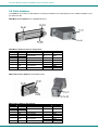
MATERIALS
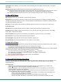
Materials Supplied with the NTI SERIMUX-TERM-CS16 Terminal Converter with Console Switch:
IEC Powercord (country specific)
DB25M-RJ45F-C
Modem Adapter
DB9F-RJ45F
Serial Adapter
+6
RJ45F-T – DB25M
Console Adapter
DB25F- RJ45F
Console Adapter
4- #10-32x3/4” screws
and cage nuts
Manual CD
Materials Not Supplied, but REQUIRED:
Serial cable with at least one RJ45 male end for connection to the Console Switch from each device to be connected. See “Serial
Port Pinouts” on page 69 for cable pinout.
3
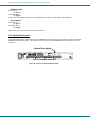
NTI RACK MOUNT CONSOLE TERMINAL WITH CONSOLE SWITCH
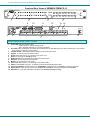
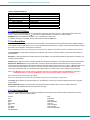
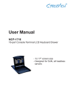
Front and Rear Views of SERIMUX-TERM-CS-16
NTI
R
SERIMUX
R
Network T echnolog ies Inc
PWR
17
18
19
20
21
22
23
24
25
26
27
28
29
30
31
32
Port
Discon
ESC
PORT
6
7
8
9
0
DISCON
0
1
2
3
4
5
6
7
8
9
10
11
12
13
14
15
16
Admin
User
ADMIN
USER
1
2
3
4
5
ENTER
3
2
1
9
NTI
R
NETWORK
TECHNOLOGIES
INCORPORATED
10
SERIAL
MONITOR
4
11
PRINTER
12
TERMINAL10 BASE T
1275 Danner Dr
Tel:330-562-7070
Aurora, OH 44202 Fax:330-562-1999
www.networktechinc.com
16
5
13 14
PARALLEL
15
14
13
12
11
6
10
9
8
7
6
5
RESET
4
ISP
3
2
1
KEYBOARD
8
7
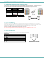
FEATURES AND FUNCTIONS
1.
2.
3.
4.
5.
6.
7.
8.
9.
10.
11.
12.
13.
14.
Power LED- indicates operation status
Green=Power-On, Video Input Signal OK
Red = Suspend / Stand-by, or no Video Input Signal
Port LEDs- LEDs will illuminate to indicate active administrator port and data traffic; also used to indicate port or user number
when entering commands from the keypad.
Command LEDs- LEDs will illuminate to indicate functions being performed
Keypad- for manual control of switch functions
Power- IEC Power Socket- for connection of AC power cord
Switch- for powering the SERIMUX On/Off
RJ45 Connectors- for attaching CAT5 cables from serial devices
Keyboard- for connecting the user keyboard
Monitor- for connecting the user monitor
Serial -Male DB9 connector- for attaching a local printer serially
Parallel- Female DB25 connector- for attaching local printer with parallel printer cable
Terminal-10/100 Base T-RJ45 Connector for 10/100 Mbps communications- for TERMINAL connection to Ethernet
System Reset- button to cycle power to the SERIMUX and TERIMINAL without powering down the SERIMUX
ISP Button- For use when restoring the firmware in the SERIMUX (factory use only)
4
NTI RACK MOUNT CONSOLE TERMINAL WITH CONSOLE SWITCH
1. INSTALLATION
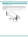
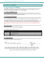
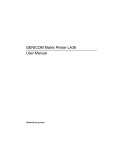
1.1 Rack Mounting Instructions
This NTI switch was designed to be directly mounted in a rack and includes a mounting flange to make attachment easy.
Install 4 cage nuts (supplied) to the rack in locations that line up with the holes (or slots) in the mounting flange on the NTI switch.
Then secure the NTI switch to the rack using four #10-32 x3/4” screws (supplied). Each screw should be of sufficient length to
go completely through the NTI mounting flange, rack frame and fully engage all threads in the captive nut. Be sure to tighten all
mounting screws securely.
Do not block power supply vents in the NTI switch chassis (if provided). Be sure to enable adequate airflow in front of and
behind the NTI switch.
Attach all cables securely to the switch and where necessary supply adequate means of strain relief for cables.
Rack
Cage Nuts
(supplied)
#10-32x3/4"
Rack Screws
(supplied)
Figure 1- Mount Switch in a Rack
5
NTI RACK MOUNT CONSOLE TERMINAL WITH CONSOLE SWITCH
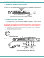
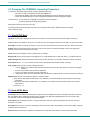
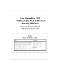
1.2 TERMINAL vs. SERIMUX Cable Connections
The connectors on the rear of the SERIMUX-TERM-CS-16 are split between those for the TERMINAL connections, and those for
the SERIMUX connections (see Figure 2).
Terminal Converter
(TERMINAL)
NTI
R
MONITOR
NETWORK
TECHNOLOGIES
INCORPORATED
SERIAL
PRINTER
PARALLEL
TERMINAL10 BASE T
1275 Danner Dr
Tel:330-562-7070
Aurora, OH 44202 Fax:330-562-1999
www.networktechinc.com
16
15
14
12
13
11
9
10
8
7
5
6
RESET
4
ISP
3
Rear View of SERIMUX-TERM-CS-16
2
KEYBOARD
1
Console Switch
(SERIMUX)
Figure 2- Distinction of connections between TERMINAL and SERIMUX
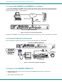
1.3 Connect Devices, Hosts, and Power
1.
Connect each serial device (or host) to be connected by the SERIMUX to any port labeled "1" through "16" using a DTE
or DCE type serial cable. It may be necessary to add one of the cable adapters (supplied) detailed in "Cable Adapters"
(page 70) between the device port on the serial device (or host) and the RJ45 connector.
Note: There are two types of serial devices, 1) data communication equipment (DCE)(i.e. modem) and 2) data terminal
equipment (DTE) (i.e. CPU), each having different connector pin assignments. The cable adapters (see “Materials” on
page 3) make the proper connections.
2.
If connecting a printer, connect either a serial printer cable to the remaining male DB9 connector or a parallel printer
cable to the female DB25 connector (see Figure 3).
3.
Connect the powercord to the IEC power connector.
Attach local printer
either by parallel cable to "Parallel"
or by serial cable to "Serial"
Rear View of SERIMUX-TERM-CS-16
IEC Power Connector
NTI
R
SERIAL
MONITOR
NETWORK
TECHNOLOGIES
INCORPORATED
PRINTER
PARALLEL
TERMINAL10 BASE T
1275 Danner Dr
Tel:330-562-7070
Aurora, OH 44202 Fax:330-562-1999
www.networktechinc.com
16
15
14
13
12
11
10
9
8
7
6
5
RESET
ISP
ETHERNET
4
3
2
1
RJ45
Male
Connector
Ethernet cable
Powercord
PBX
ROUTER
FIREWALL
SERVER
Figure 3- Connect serial devices, printer, and power cord
6
KEYBOARD
NTI RACK MOUNT CONSOLE TERMINAL WITH CONSOLE SWITCH
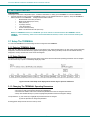
1.4 Connect the SERIMUX and TERMINAL to a Network
To control the SERIMUX and TERMINAL through a network connected PC, connect a CAT5 Ethernet network cable to the
connector marked "TERMINAL-10 BASE T". Then connect the other end of the Ethernet cable to a Local Area Network (LAN)
through a 10/100 BaseT switch or hub (see Figure 4).
VGA
Multi-Scan
Monitor
LAN
Ethernet cable
RJ45
Male
Connector
Control Terminal
NTI
R
MONITOR
NETWORK
TECHNOLOGIES
INCORPORATED
SERIAL
PRINTER
PARALLEL
TERMINAL10 BASE T
1275 Danner Dr
Tel:330-562-7070
Aurora, OH 44202 Fax:330-562-1999
www.networktechinc.com
16
15
14
13
12
11
10
9
8
7
5
6
RESET
4
Network
Server
ISP
3
2
KEYBOARD
1
Rear View of SERIMUX-TERM-CS-16
Figure 4- Connect to a Local Area Network (LAN)
Alternatively, the TERMINAL may be directly connected to a PC using a CAT5 Crossover cable. See page 69 for specifications.
1.5 Connect the Monitor and Keyboard
Connect a VGA monitor and PS/2 keyboard to the connectors marked “MONITOR” and “KEYBOARD”.
Rear View of SERIMUX-TERM-CS-16
NTI
R
MONITOR
NETWORK
TECHNOLOGIES
INCORPORATED
SERIAL
PRINTER
PARALLEL
TERMINAL10 BASE T
1275 Danner Dr
Tel:330-562-7070
Aurora, OH 44202 Fax:330-562-1999
www.networktechinc.com
16
15
14
13
12
11
10
9
8
7
6
5
RESET
4
ISP
3
2
KEYBOARD
1
6 miniDIN
male connector
15HD male
video connector
VGA
VGA
Multi-Scan
Monitor
Monitor
PS/2 Keyboard
Figure 5- Connect User's Monitor and Keyboard
1.6 Power Up The SERIMUX-TERM-CS-16
1. Connect the powercord to a power source and power-ON the SERIMUX using the switch on the rear of the
SERIMUX-TERM-CS-16.
2.
Power-ON the connected VGA monitor.
7
NTI RACK MOUNT CONSOLE TERMINAL WITH CONSOLE SWITCH
2. GETTING STARTED
Introduction
This chapter covers basic configuration topics. Included is information on setting up the TERMINAL to control the SERIMUX.
1. Using the instruction under “Setup The TERMINAL” below (or more detailed instruction on page 37), setup the TERMINAL to
make connection to the SERIMUX. Configure the terminal as follows:
•
Ethernet Mode set to OFF (F4 menu)
•
Baud rate at 9600 bps (F4 menu)
•
8 bits (F4 menu)
•
no parity (F4 menu)
•
1 stop bit (F4 menu)
•
no flow control (F4 menu)
•
ANSI or VT100 terminal mode (F2 menu).
Within the SERIMUX firmware, the "CONSOLE" port is the internal connection between the TERMINAL and the
SERIMUX. For consistency, when Port 0 is mentioned within this manual, it refers to the connection made by the
TERMINAL.
2.1 Setup The TERMINAL
To control the SERIMUX some initial settings must be configured in the TERMINAL.
2.1.1 Entering TERMINAL Setup
Hold down the [ ALT] key and press the [ Esc] key to enter Setup mode. When entering Setup, any text on the screen temporarily
disappears, and the main SETUP directory appears (See Figure 6). When leaving the Setup mode, the main SETUP directory
disappears, and any text that was on the screen will reappear.
2.1.2 Setup Directory
The fields at the bottom of the screen show the various setup menus where the terminal's operating parameters can be changed
and the function key to press to immediately display any menu.
Figure 6- Fields in the Setup menu display which function keys to press for submenus
2.1.3 Changing The TERMINAL Operating Parameters
To select one of the setup menus shown, press the indicated function key.
- The screen for that menu appears with the name highlighted.
- The fields at the middle of the screen indicate the parameters that can be changed in that menu.
- The top line identifies the keys to press to highlight the parameter fields and change the settings.
The procedure is: (1) Use arrow key to highlight the parameter field to be changed.
(2) Use the Spacebar to change the parameter.
Pressing [F12> always returns the user to the top menu.
8
NTI RACK MOUNT CONSOLE TERMINAL WITH CONSOLE SWITCH
The following lists only what is necessary to connect to SERIMUX. For a complete list of features, see page 37.
F2- Genrl SETUP Menu
Personality set to Digital Equipment VT-100 or Console ANSI
F4- Comm SETUP Menu
Baud Rate set to 9600
Ethernet Mode set to OFF to set the communication routing by Serial Port.
Data / Stop Bits set to send and receive 8-bits data with one stop bit
Xmt Handshake set to None
Parity set to none
2.1.4 Saving and Exiting Setup
The first menu seen when entering Setup serves as a directory to the other Setup menus. To exit Setup or any submenu, press
[ F12]. Pressing [ F12] will return the display to the main Setup directory and with another press of [ F12] the user will exit
Setup.
The highlighted field at the right of the screen gives the user the choice of saving or not saving parameter changes into
memory before returning the TERMINAL to the normal operating mode. Settings changed will effect the operating environment
until the TERMINAL is powered-down. Setting changes will only be restored at power-up if they are saved before exiting Setup.
Note: If settings are not saved before exiting Setup, any new selections will be lost when the SERIMUX is powereddown.
To save Setup selections, depress the Spacebar to change the save field at the right side of the screen from NO to YES before
exiting Setup. (Table 1 describes your options for exiting Setup.)
Press [ F12] to leave Setup and return to the normal display mode.
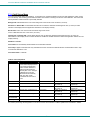
Table 1- Main Setup Menu (F12) Exit Functions
Option
Function
No
Returns terminal to normal operating mode without saving parameters changes for power up
Saves all changes (operating parameter, tabs, key definition, and answerback message); returns terminal
Yes
To its normal operating mode.
Restores all setting (operating parameters, tabs, key definitions, and answerback message) to their factory
Shift + Esc
default values.
For changes to the TERMINAL settings to take effect, the RACKMUX must be power cycled.
adapter and reconnect.
Disconnect power from the AC
2.2 Connect to the SERIMUX
1. Press [ Enter] on the keyboard to be recognized as the default SERIMUX user. The "Accessible host list" for "User01",
logged in at "Port00" will be displayed (see Figure 7). By default, all ports are configured as Host ports and all are accessible.
Note: If the user menu does not display, re-initialize the SERIMUX following the "Reset SERIMUX Console Switch to
default settings" instructions on page 36.
9
NTI RACK MOUNT CONSOLE TERMINAL WITH CONSOLE SWITCH
2.
To connect to an attached CPU, enter the number of the port the CPU is connected to and press [ Enter].
Figure 7- Startup- Accessible host list
10
NTI RACK MOUNT CONSOLE TERMINAL WITH CONSOLE SWITCH
3. USING THE SERIMUX CONSOLE SWITCH
The SERIMUX-TERM-CS-16 is controlled using
•
Terminal Control- using a connected keyboard, VGA Monitor and the built-in TERMINAL
•
Serial Control- from a "dumb" terminal- locally-connected
- through an external modem from a remote location
•
Keypad Control (reduced set of commands)
Terminal Control
The TERMINAL built-in to the SERIMUX-TERM-CS-16 can quickly provide access to the Console Switch (see page 8).
Serial Control
The SERIMUX Console Switch can be easily configured using serial communications from either a locally-connected “dumb”
terminal or from a terminal remotely connected through a modem. Using a keyboard-controlled menu, the user can modify
various parameters and options for each port. The administrator menu can be accessed by the administrator for full feature
control, or the user menu, by any user, for more restricted control of port connections.
Keypad Control
The keypad has direct control over basic SERIMUX functions. The keypad can be used to make changes to port connections
regardless of any menu control taking place. Command LEDs on the front panel of the SERIMUX Console Switch indicate the
status of the switch and what function is being performed. For more on Keypad Control, see page 33.
Note: The keypad will only work after first entering the assigned PIN number. See page 33 for more info.
The default keypad PIN number is 9999.
The SERIMUX can be easily configured using the TERMINAL with a keyboard-controlled menu to modify various parameters and
options for each port to be connected to a device. The administrator menu can be accessed by the administrator for full feature
control, or the user menu, by any user, for more restricted control of port connections.
The SERIMUX supports 2 operator levels, administrator and user, each with separate password protection for security.
• The administrator logs in using an administrator password (see next page for login procedure)
administrator name : [root] (all lowercase letters)
administrator password : [nti] (all lowercase letters)
•
Users login using a password set by the administrator
FYI: Users may be granted administrative access rights by the administrator.
The administrator and any user with administrative rights is able to:
• view / modify port parameters;
• view / modify user parameters and user access rights to ports;
• disconnect ports, logout users etc.
• connect to host ports
11
The administrator name cannot be
changed.
To change the administrator
password, see page 23.
NTI RACK MOUNT CONSOLE TERMINAL WITH CONSOLE SWITCH
3.1 Administrator Controls
3.1.1 Login as the administrator
1.
3.
4.
The TERMINAL must first be configured (and is typically delivered preconfigured) as described on page 8 under "Getting
Started”.
Press [ Enter ] on the keyboard, wait three (3) seconds, and the port will open to the "Accessible host list" for "User01",
logged in at "Port00".
Press [ Esc] to logout, and [Y] to confirm. A message will be displayed "Disconnecting user now"
Press [Spacebar] or [ Enter].
A prompt requesting a Username will appear.
5.
Enter [root] (all lowercase letters) and press [ Enter]. A prompt for a password will appear.
6.
Enter [nti] (all lowercase letters) and press [ Enter].
port 1.
2.
The “Administrator main menu” will appear for user ROOT on
Note: This will only enter the administrator mode if the administrator password has not yet been changed from "nti".
FYI: If SERIMUX is not at initial power-ON, omit steps 2 and 3 above to login.
Figure 8- Administrator main menu
FYI: The Administrator main menu will also appear if a user with administrative privileges presses [4] from the User main
menu.
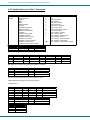
From the Administrator main menu, the following options are possible:
Function
Port List
Port settings
Port disconnect
Port Connect
User list
User settings
User disconnect/logout
Advanced settings
Return to user menu
Logout
Description
Display the port list
View or modify any port settings
Disconnect any port and logout the user logged in or connected to the port
Connect to any port .
Display the user list
View or modify user settings
Disconnect and logout any user connected to a port
View or modify advanced administrative settings (pg 17)
Leave the administrative menu and return to the User main menu (only
listed when a user with administrative rights is logged in)
Logout from SERIMUX
12
Keystroke
[1]
[2]
[3] + [port #]
[4] + [port #]
[5]
[6]
[7]
[8]
[9]
[0]
NTI RACK MOUNT CONSOLE TERMINAL WITH CONSOLE SWITCH
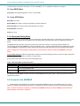
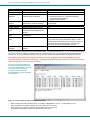
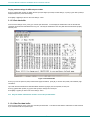
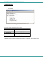
3.1.2 Port List
From the Administrator main menu, press [1] to display the Port List.
Figure 9- The Port list displays the status of all ports
The Port list displays the following information:
Column Heading
Port
Log
Con
U/H
Mdm
BaudRate
Serial
Flow
Xon/Xoff
Discon
DscTime
Description
Port number and name
Index number of the user logged in at the port
The number of another port (Pxx) connected to that port . If the administrator is
logged in, "Adm" will be displayed
Port type- User or Host
Modem connection status: Y if modem is connected , - if not
Port transmitter and receiver speed
Character size, parity, and stop bit number
Flow control method- hard (RTS/CTS), soft (Xon/Xoff), both, or none
Special characters used as soft flow control sequence
In-band disconnect sequence (1 character, 3 character, or none)
Remaining time until self-disconnection due to port receiver inactivity (see
below)
13
NTI RACK MOUNT CONSOLE TERMINAL WITH CONSOLE SWITCH
FYI: RE: DscTime ( Disconnect Time)
The value shown in the Port list is derived from various sources depending on the type of connection active at the time.
- If a user is logged into a port as just a user, the time shown will be the remaining time based on the user's
timeout setting.
- If a user is logged in with administrative privileges and performing administrative tasks, the time will be based
on the administrator's timeout setting, not based on the user's timeout setting.
- If two ports are connected to each other, and one port has a lower timeout setting than the other, the lower
setting will be shown in the DscTime column and control the connection.
-
Press [N] to display port information for ports greater than 16, and then [P] to see the previous page.
Press [R] to refresh the information displayed
Press [Esc] or [Spacebar] to return to the Administrator main menu
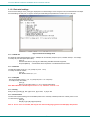
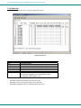
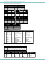
3.1.3 Port Settings
From the Administrator main menu, press [2]-[x]-[Enter]] where x is the number of the port to display the port settings for.
Figure 10- The Port settings menu
14
NTI RACK MOUNT CONSOLE TERMINAL WITH CONSOLE SWITCH
From the Port settings menu, the configuration of each port can be viewed and changed.
Setting
Port name
Port type
In-band disconnect
sequence
Description
Change the port name
Host or User
Select characters to use for inband disconnect sequence
Connection
Timeout
Serial settings
Modem settings
View port data
buffer
Time left before connection will be
broken due to receiver inactivity
Display serial settings menu
Display modem settings menu
View the last 508 characters
received and transmitted to/from
the port
Clear the data buffer for the
selected port
Modify the displaying extra delay
Clear port data
buffer
VT100 displaying
delay
Reset Port settings
to default
Value
Max. 15 characters
H or U
1 + code for 1-character sequence (see Fig. 6 below)
3 + desired characters for 3-character sequence
0- for no disconnect sequence
T- display Control code list
0-90 minutes. If 0 is selected, the connection will
never timeout.
N/a
N/a
N/a
N/a
0 = None,1 = normal, 2 = double, or 3 = triple
"None" value can be used if the display is faster (i.e. with a
terminal emulator, like HyperTerminal, running on a PC); the
other values are useful if real terminals or slower serial
devices are used as user/administrator consoles.
Restores factory default port
settings
A confirmation "Y" will be required
When [3] is pressed to change the in-band disconnect sequence, the choices provided are 0, 1, 3, or T. Pressing a [T] will bring
up a Control code list containing key sequences used for 1-character sequences, and the ASCII codes associated with each.
(See Fig. 10) To set a 1-character sequence, press [1], then the code from the table associated with the desired sequence.
Note: If the 3-character disconnect sequence is enabled, the string: [CR][LF]<3-char sequence>[CR][LF] has to be
received to break the connection (7 characters). The [CR] and [LF] ASCII characters stand for 13 and 10 decimal codes
(ASCII Carriage Return and Line Feed) respectively.
FYI: If the 1-character sequence is
selected, the connected device will
not receive the disconnect character.
If the 3-character sequence is
selected, it will be sent to the
connected device, prior to breaking
the connection.
Figure 11- Control Codes for in-band disconnect sequence
-
When selecting each new port setting values, press [Esc] or [Spacebar] to cancel, or press [Enter] to save.
Press [>] (greater than symbol) to display the current settings for the next port.
Press [<] (less than symbol) to display the current settings for the previous port
Press [Esc] or [Spacebar] to return to the "Administrator main menu"
15
NTI RACK MOUNT CONSOLE TERMINAL WITH CONSOLE SWITCH
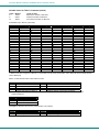
3.1.3.1 Port serial settings
From the "Port settings" menu, press [5] to display the "Port serial settings" menu. Using this menu, the administrator can adjust
the serial settings of each port, or copy the current port serial settings and paste them to another port or to all ports.
Figure 12- Port serial settings menu
3.1.3.1.1 Baud rate
Any baud rate (serial speed) between 50 bps - 128Kbps can be selected, (except for port 0, between 300 bps - 115.2 Kbps).
To modify the port serial speed (baud rate);
– press [1],
– enter the new value or press [T] for a table listing standard baud rates supported,
– and press [Enter]. A confirmation will be required for non-standard baud rate values.
3.1.3.1.2 Data bit
The data bit number can be 5, 6, 7, 8, (except for port 0: 7 or 8).
To modify the data bit number;
– press [2],
– then the bit number: 5, 6, 7, 8
3.1.3.1.3 Stop Bit
The stop bit number can be 1, 2, or 1.5, (except for port 0: 1 or 2 stop bits).
To modify the stop bit number;
– press [3],
– then [1] or [2] or [A] to select 1, 2, or 1.5 stop bits respectively.
Note: When Data bit is 5/6 the stop bit can be 1 or 1.5, otherwise it can be 1 or 2
3.1.3.1.4 Parity
Parity is set by pressing [4], then [N] for none, [E] for even, or [O] for odd.
3.1.3.1.5 Flow Control
The flow control (hand shaking) can be hardware (RTS/CTS or out-band), software (Xon/Xoff or in-band), both or none.
To select the flow control;
– press [5],
– then [H] or [S] or [B] or [N] respectively.
Note: If "N" for "none" is selected, data may be lost when sending large (greater than 1000 byte) data packets.
16
NTI RACK MOUNT CONSOLE TERMINAL WITH CONSOLE SWITCH
Note: If a modem is attached to the port, and hardware and/or software flow control is used, the appropriate command
may be added to the modem initialization string:
Flow control
None
RTS/CTS (hardware)
Xon/Xoff (software)
Both
disable flow control (not necessary)
Command 1
–
&K3
&K4
&K6
&K0
Command 2
–
\Q3
\Q1
\Q0
Consult your modem user manual or the modem AT command manual to find the suitable command.
3.1.3.1.6 Xon or Xoff Characters
Any non-printable character (ASCII codes between 0 and 31) can be used as flow control Xon or Xoff character. The software flow
control is transparent, so the special character is not passed to the connected device. If the Xon and Xoff characters are equal, a
toggle mode is automatically used in the software flow control: whenever the special flow control character is received, the current
state of flow control is toggled.
To change the Xon or Xoff character;
– press [6],
– then [0] for Xoff or [1] for Xon,
– enter the new value,
– then press [Enter] to save it, [Esc] or [Space] to cancel.
FYI: Press [T] after [6] to display a control codes table.
3.1.3.1.7 DTR line behavior
If a modem is not attached to the serial port, the DTR port line behavior on port disconnection can be selected as follows: the DTR
line can be held high (active), low (inactive) or pulsed for 0.5 seconds and then held high. When a modem is attached to the port,
the DTR line will be pulsed on port disconnection, disregarding this parameter value.
To modify the DTR line behavior on port disconnection;
– press [8],
– then [H] or [L] or [P] respectively.
3.1.3.1.8 Inter-character delay
An inter-character delay (1 - 60 ms) may be defined, each time a character sequence is transmitted from the port. Using this
command, a minimum pause will appear between transmitted characters; for example, certain types of electro-mechanical devices
(like teletype equipment) cannot process received characters continuously at their specified baud rate.
To select an inter-character delay;
– press [8],
– enter the new value (0 for no delay),
– and press [Enter] to save it, [Esc] or [Space] to cancel.
FYI: This parameter is not available for port 0.
3.1.3.1.9 Line-break receive or transmit
It is possible to accept the line-break received from a port, and to send it from the connected port. The break condition (when
received) is defined as zero data with zero parity and no stop bits.
To allow or not the line-break receive;
– press [9],
– then [Y] for allowed,
– [Esc] or [Space] to cancel, any other character to deny.
To define the transmitted line-break extra-duration (this is added to the 1-character transmission time);
– press [0],
– then enter the new value (1 - 999 ms) or 0 to disable it,
– and press [Enter] to save it, [Esc] or [Space] to cancel.
FYI: These parameters are not available for port 0.
17
NTI RACK MOUNT CONSOLE TERMINAL WITH CONSOLE SWITCH
3.1.3.1.10 Copy Port Serial Settings
– Press [+] to select the current port as source in a port settings copy-paste process (except port 0).
– Then, press [*] to paste the port settings.
– Press [Y] to paste the selected port settings to the current port, [A] to paste to all ports, [S] to specify the
destination port, or press any other key to cancel.
3.1.3.1.11 Display serial settings for different port number
Press [>] (greater than symbol) to display the next higher port serial settings, or press [<] (less than symbol) to display the
previous port serial settings.
Press [Esc] or [Space] to return to the "Port settings" menu.
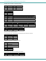
3.1.3.2 Modem settings
From the "Port settings" menu, press [6] to display the "Modem settings" menu.
Remote connections are possible if modems are used, usually by the users. The remote modem may call in to a local modem
attached to a SERIMUX port. A minimum number of port modem settings can be adjusted in the SERIMUX to control the
connection (try the default values first; refer to the manual(s) for the modems otherwise).
Figure 13- Modem settings menu
The administrator can initialize a modem attached to a SERIMUX port, or disconnect the modem. To control the modem
connection from the "Modem settings" menu, the following functions are possible:
Function
Keystroke
Attach and initialize a modem
[1] - [A]
FYI: If an old modem is attached to a SERIMUX port, it may
Disconnect a modem
[1] - [D]
be necessary to enable the “Hang-up on “NO CARRIER”
Change the modem reset string
[2]
message” option, in order to hang-up and disconnect the
Change the initialization string
[3]
attached modem when receiving this message. Press [5],
Change the hangup string
[4]
then [Y] to enable or any other key to disable this option.
Enable hangup on "NO CARRIER"
[5]
Usually, this option should remain disabled.
Save the changes
[Enter]
Cancel the command
[Esc]
Reset to default values
[0]-[Y]
.
– Press [+] to select the current port as source in a port modem settings copy-paste process (except port 0).
– Then, press [*] to paste the port settings.
– Press [Y] to paste the selected port settings to the current port, [A] to paste to all ports, [S] to specify the
destination port, or press any other key to cancel.
18
NTI RACK MOUNT CONSOLE TERMINAL WITH CONSOLE SWITCH
Display modem settings for different port number
Press [>] (greater than symbol) to display the next port (next higher port index) modem settings, or press [<] (less than symbol) to
display the previous port modem settings.
Press [Esc] or [Space] to return to the "Port settings " menu.
3.1.3.3 Port data buffer
From the "Port settings" menu, press [7] to view the port data buffer. In this display the administrator can see the last 508
characters received and transmitted to/from any port. This way the administrator can verify that data was transferred properly
between ports.
Figure 14- Port data buffer
Press [ P ] to see the previous (older) 128-character page information; press [ N ] to see the next (newer) 128-character page
information.
Up to 508 received characters and 508 transmitted characters (4 pages) can be inspected, for each port.
Press [>] (greater than symbol) or [<] (less than symbol) to change the current port.
Press [Esc] or [Space] to return to the "Port settings " menu.
FYI: Only the "ROOT" administrator is able to access the port data buffer.
3.1.3.4 Clear Port data buffer
From the "Port settings" menu, press [9] to clear the port data buffer. This selection will clear the entire buffer for data received
by or transmitted from the respective port.
19
NTI RACK MOUNT CONSOLE TERMINAL WITH CONSOLE SWITCH
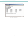
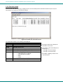
3.1.4 User List
From the administrator main menu, press [4] to display the User list.
Figure 15- User List
Column Heading
User
User Name
En
Adm
Port access
Log
Con
-
-
Description
User Index number
User name associated with the index number
User status- "Y" = enabled " -" = not enabled
Displays if user has administrative rights "Y" = yes "-" = no
Displays what ports the user has access to
Identifies what port the user is logged into, if any
Identifies what port the user is connected to (Pxx)
Or if the user is logged in as an administrator (Adm)
Or if the user is just logged in (Usr)
Press [R] to refresh the information and repaint the screen.
Press [N] to see the next page; press [P] to see the first page.
Press [Esc] or [Space] to return to the "Administrator main menu".
20
NTI RACK MOUNT CONSOLE TERMINAL WITH CONSOLE SWITCH
3.1.5 User Settings
From the "Administrator main menu", press [5], enter the user index number, then press [Enter].
The screen will show the current user number and name and the user settings menu:
Figure 16- User settings menu
Setting
User name
Password
User enabled
User menu timeout
Administrator
privileges
Port access
User initial screen
Reset user settings
to default
-
Description
Change the user name
Define the user password, if any
Enable or disable user
Time interval of user inactivity
before auto logout of the user will
occur
Enable administrative privileges for
user
Define ports user has access to.
Displays user's Port access list
(Fig.16)
Select the initial user menu to
display upon user login
Value
Max. 15 characters, use backspace to delete
Max. 31 characters, use backspace to delete
Y to enable, any other character to disable
0-90 minutes 0 = never
Y to enable, any other character to disable
1 + port number to grant access to a port
0 + port number to deny access to a port
< or > to change to different user access list
M = User main menu
H = Accessible host list
T = Terse mode
A confirmation "Y" will be required
Restores factory default user
settings
When selecting each new user setting values, press [Esc] or [Spacebar] to cancel, or press [Enter] to save.
Press [>] to display the current settings for the next port.
Press [<] to display the current settings for the previous port
Press [Esc] or [Spacebar] to return to the Administrator main menu
21
NTI RACK MOUNT CONSOLE TERMINAL WITH CONSOLE SWITCH
Figure 17- Port access list for User 01
3.1.5.1 Port access
To quickly grant/deny user access to multiple ports, the use of a dash (-) and/or comma may be used in conjunction with the [1] (to
grant) or [0] (to deny) command.
i.e.
[1] - [1-4,7,9,15] will grant access to ports 1 through 4, 7, 9, and 15, all in one command string
3.1.5.2 Copy User Settings
From the User settings menu,
press [+] to copy the current user's user settings to memory
press [*] (asterisk) to start the paste function. Three options are available:
Option
Y
A
Sxx
Description
Apply the settings in memory to the current user shown
Apply the user settings in memory to all users
where xx is 01-16- apply the user settings in memory to a specific user
The "Y" option is particularly useful if the administrator wants to place a particular user's settings into memory and move around to
other users (using the [<] or [>] keys) to review their settings before pasting the settings into memory over them.
The "S" option will allow the administrator to paste settings into memory to a specific user without having to view that user's
settings list.
22
NTI RACK MOUNT CONSOLE TERMINAL WITH CONSOLE SWITCH
3.1.6 Advanced Settings
From the "Administrator main menu", press [7] to display the “Advanced settings” menu.
Figure 18- Administrator's Advanced settings menu
From the "Advanced settings" menu the administrator can perform the following functions:
Setting
Administrator
Password
Description
Define the password to be used by the
administrator
Administrator
Timeout
Unit name
User to auto login
the time interval of administrator
inactivity, prior to logging out.
Name assigned to the SERIMUX
User assigned to automatically login at
power up without a password.
Connect two host
ports
Firmware
Auto Refresh Period
Connect two host ports together
Local KeyPad PIN
Value
Max. 31 characters.
This can only be changed if old password is known.
(If SERIMUX is re-initialized (pg 30), the default password
(“nti”) will be restored)
0-90 minutes 0 = Never
Max. 40 characters
Index number of any enabled user that has access to the port
being used for the user port
Enter host port index number, press [Enter], second host port
index number, and press [Enter] again
See pg. 19
0-90
Display the firmware menu
Refreshes the admin screen after xx
minutes
Defines the PIN number for Local
keypad
4 digit value 0000-9999 (default value is 9999)
FYI: If at power up the auto-login user does not have access to port being used, a login by a valid user with
access rights will be required.
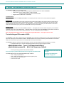
3.1.6.1 Change administrator password
For security purposes the administrator should change the factory default administrator password to a unique password. This will
prevent unauthorized access to switch functions and CPUs. The password is needed to log in from any device, connected to any
SERIMUX port in buffer mode.
To change the administrator password, from the Administrator main menu;
- press [7] to choose Advanced settings and press [Enter]. The Advanced settings menu will appear (Figure 18)
- press [1] and a prompt for the old password will appear
- enter the old password (factory default password is "nti") and press [Enter]
- enter a new password (maximum 31 ASCII characters), using the [Backspace] key to erase any characters entered
in error, and press [Enter]
- re-enter the password to confirm it, and press [Enter]
- a message "OK" will appear, press any key to return to the Advanced settings menu
Note: The password entered will be case sensitive so be sure to note what characters are used and what case they are in
if any are alphabetical. The password characters are displayed as ‘*’ (asterisk) characters while entering them.
Note: If the administrator password is not known, the administrator must re-initialize the SERIMUX following the "Reset
SERIMUX Console Switch to default settings" instructions on page 30.
23
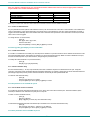
NTI RACK MOUNT CONSOLE TERMINAL WITH CONSOLE SWITCH
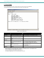
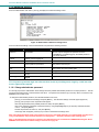
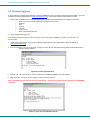
3.1.6.2 Firmware
From the Advanced settings menu, press [6] to display the Firmware menu. (From Administrator main menu press [7]-[6])
Figure 19- Firmware menu
The Firmware menu has three possible functions:
Function
Description
1. About Firmware
Provides information about SERIMUX including revision number, code length, and CRC
2. Load new firmware
Initiate firmware upgrade (see Firmware Upgrade on page 31)
3. Save current firmware
Save present firmware in SERIMUX to binary file
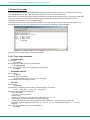
3.1.6.2.1 Load new firmware
To upgrade the firmware that controls the Console Switch, as soon as improved versions become available, download the
firmware file (from the NTI website at www.networktechinc.com) to a local CPU, and follow the instructions under "Firmware
Upgrade" on page 31 to install it.
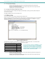
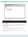
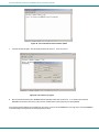
3.1.6.2.2 Save current firmware
In order to save the firmware currently in SERIMUX, perhaps before installing new firmware, from the Firmware menu:
press [3] for Save current firmware. The message shown in Figure 20 will appear.
Note: In order to save the current firmware, the user must be using a CPU connected through port 1 (as described under
“Firmware Upgrade” on page 31.
24
NTI RACK MOUNT CONSOLE TERMINAL WITH CONSOLE SWITCH
Figure 20- The SERIMUX is waiting to save its firmware
The terminal program in the CPU connected to Port 1 must be configured for Xmodem protocol.
1. Receive the binary file from the SERIMUX (for example, in HyperTerminal for Windows, use the Transfer -> Receive File
command).
2. When saving the file, choose a directory to place the file in and a name that will identify it with the extension " .bin" (i.e.
SERIMUX1_8.bin).
With the file saved, it can be restored to the SERIMUX at any time if desired.
25
NTI RACK MOUNT CONSOLE TERMINAL WITH CONSOLE SWITCH
3.2. User Controls
Users can connect only to accessible ports as defined by the administrator. A list of those ports will be displayed with a
successful login. Connection can be made using the TERMINAL, or a serial terminal with an emulator (e.g. Windows
HyperTerminal) connected to the SERIMUX at an allowed user port
To login, press the [Spacebar] or [Enter] key. Users can login by entering a valid name and password, assigned by the
administrator. When prompted for a "User name:", type the administrator assigned user name and press [Enter]. When
prompted for the "Password:", type the administrator assigned password and press [Enter].
Note: User names and passwords are case sensitive. It is important to know what characters must be capitalized and
what characters must not.
FYI: The administrator may select a user that will automatically login at power up (User 1 is setup by default). In this
case, neither name nor password will be required, just press [Spacebar] or [Enter] after powering ON the TERMINAL or
opening the connected terminal emulator.
After login, the user may connect to an allowed host port, or view host status and parameters. The user is unable to modify port
parameters unless the user has been granted administrative privileges.
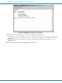
3.2.1 User "Accessible host list" screen
After successful login, the "Accessible host list" will be displayed. The administrator may choose another initial screen to be
displayed, following user's preferences. The Accessible host list includes:
• user index number and name
• index number and name of the login port
• index numbers and names of accessible hosts
Figure 21- A user with limited host port access
From the "Accessible host list", the user can perform the following functions:
Function
Connect to host
Refresh the screen
Logout
Keystroke
[xx] - [Enter] (where xx is the port index number)
[Spacebar]
[Esc] or [Ctrl]+[X] , then [Y] to confirm
FYI: The port index numbers are 2-digit decimal numbers. If the wrong number is entered, simply enter the correct
number. Only the last two numbers entered before the [Enter] key is pressed will be accepted. The [Enter] key
validates the command; [Esc] or [Spacebar] cancels it.
26
NTI RACK MOUNT CONSOLE TERMINAL WITH CONSOLE SWITCH
3.2.2 User main menu
The User main menu includes:
• user index number and name
• index number and name of the login port
• user command list
Figure 22- User main menu
From the "User main menu" the following functions are possible:
Function
Connect to host port
Display Accessible host list
Display accessible host and user
ports and info about each
Login as administrator
Logout
Refresh the screen
Keystroke
[1]-[xx]-[Enter]
(where xx is the port index number)
[2]-[Enter]
[3]-[Enter]
[4]-[Enter]
(only works if user has administrative rights)
[0] then [Y] to confirm
[Spacebar]
A user can only connect to the hosts the user has been allowed access to by the administrator. Press [2] to display a list of
accessible hosts.
27
NTI RACK MOUNT CONSOLE TERMINAL WITH CONSOLE SWITCH
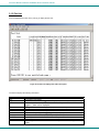
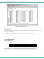
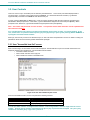
3.2.3 Port List screen
From the "User main menu", press [3] to display the list of user accessible ports and information about these ports. Only the
administrator can change the communication settings.
Figure 23- A limited user accessible Port list
On consecutive columns, the following are displayed:
Column
Description
Port
index number of the port
Port Name
Name assigned to the port
Usr/Hst
Port type, user or host
Modem
Yes if modem is attached, - if not
BaudRate
Receiving and transmitting speed of the port
Serial
Character size, parity, and stop bit number
Flow
Defines flow control method
• Hard (RTS/CTS or outband)
• Soft (Xon/Xoff or inband)
• Both
• None
Xon/Xoff
Characters used for Xon and Xoff flow control
Discon
In-band disconnect sequence (1-3 characters, or none)
28
Press [R] to refresh and re-display the
information on the screen.
If the number of user accessible ports is
greater than 17,
press [N] to see the next page,
press [P] to see the first page.
Press [Esc] or [Space] to return to the
"User main menu".
NTI RACK MOUNT CONSOLE TERMINAL WITH CONSOLE SWITCH
3.2.4 User Terse mode
This mode is especially useful when the SERIMUX is directly controlled by external software from a serial console (as a user
without administrative privileges), rather than being controlled by a user from a keyboard interface.
Entering short command strings performs functions similar to the user main menu commands. A [CR] – [LF] sequence ends every
string. The commands are not echoed; the SERIMUX returns to the serial console a specific answer if the command is
successfully accomplished or an error message otherwise.
Terse mode can be used only if the administrator configures a user port to enter into Terse mode at login (see page 21). If a
keyboard-based user logs into a port intended for Terse mode operation, the following image will appear:
Figure 24- User port in Terse mode
From Terse mode, a limited number of functions are possible;
3.2.4.1 Terse mode commands
¾ Connect to port
Send or type in:
[C] xx [Enter]
where xx is the port index number. The answer will be:
OK [CR][LF][LF][FF]
If an error occurs (i.e. the port is not accessible), the answer will be:
Err [CR][LF]
¾ Accessible host list
Send or type in:
[H] [Enter]
The answer may be, for example:
02,03,04,05,06,07,08,09,10,11,12,13,14,15,16 [CR][LF]
(the accessible hosts, separated by commas)
¾ Port info
Send or type in:
[P] xx [Enter]
where xx is the accessible port index number. The answer may be, for example:
04,H, 9600,8N1 ,N,QS,1X
[CR][LF]
where the comma separated fields stand for:
- port index number;
- port type: U or H for User or Host;
- port baud rate;
- data bits (5..7), parity (N, E, O for None, Even, Odd), stop bits (1, 1.5, 2,);
- flow control (N, H, S, B for None, Hard, Soft, Both respectively);
- in-band (soft) flow control Xon and Xoff characters (in this example Xon = [Ctrl+Q] and Xoff = [Ctrl+S]);
- disconnect sequence length and sequence (i.e. “0 ” for none, “1X ” for 1-char [Ctrl+X] sequence, “3```” for 3-char ```
sequence);
If the port is not accessible to the user, the answer will be:
Err [CR][LF]
29
NTI RACK MOUNT CONSOLE TERMINAL WITH CONSOLE SWITCH
¾ Verbose mode
Send or type in:
[V] [Enter]
The answer will be:
OK [CR][LF]
and the Terse mode will be terminated. The “Accessible host list” or the “User main menu” will be displayed.
¾ User Logout
Send or type in:
[L] [Enter]
The answer will be:
OK [CR][LF]
With the next login of the same user, Terse mode will resume.
3.2.5 System Reset button
The “System Reset” button, located on the rear of the RACKMUX (see Figure 25), may be pressed at any time to refresh the
SERIMUX without powering it OFF. This might be necessary in the event the SERIMUX should fail to respond to normal
commands.
System Reset button
NTI
R
MONITOR
NETWORK
TECHNOLOGIES
INCORPORATED
SERIAL
PRINTER
PARALLEL
TERMINAL10 BASE T
1275 Danner Dr
Tel:330-562-7070
Aurora, OH 44202 Fax:330-562-1999
www.networktechinc.com
16
15
14
13
12
11
10
9
8
7
6
5
RESET
4
ISP
3
2
Rear View of SERIMUX-TERM-CS-16
Figure 25- Location of Restore Defaults button
30
1
KEYBOARD
NTI RACK MOUNT CONSOLE TERMINAL WITH CONSOLE SWITCH
3.3 Firmware Upgrade
It may be desired to upgrade the firmware that controls the SERIMUX as soon as improved versions become available. Once the
firmware file has been downloaded from www.networktechinc.com to a local CPU, follow these instructions to install it.
1. Using a CPU connected to Port 1, start a terminal program (e.g. Windows HyperTerminal) and configure it as follows:
•
direct connection (using the appropriate CPU local serial Com port)
•
9600 bps
•
8 bits
•
no parity
•
1 stop bit
•
no flow control
•
ANSI or VT100 terminal mode.
2. Log-in as administrator (page 12).
Note: During the transfer and the internal upgrade, all ports (except the TERMINAL and Port 1) and all users are
disconnected.
3. Locate on the local hard disk the binary file containing a valid firmware version (downloaded from the NTI website at
www.networktechinc.com).
4. From the "Firmware" menu (pg 24) press [2], then [Y] to confirm. All other ports will be disconnected and disabled during the
firmware update procedure.
.
Figure 26- Firmware upload window
5.
Type [A] + [T] “AT” (case sensitive, must be uppercase) to activate the SERIMUX auto baud detection.
6.
When prompted, press [Y] to confirm, and [C] to continue with the procedure.
Note: Proceeding past this point will erase all programming. The firmware upgrade must be completed for the SERIMUX
to function.
Figure 27- Type "AT" to auto-detect baud rate
31
NTI RACK MOUNT CONSOLE TERMINAL WITH CONSOLE SWITCH
Figure 28- Last confirmation before firmware update
7.
Using the terminal program, send the binary firmware file using “1K Xmodem” protocol.
Figure 29- File transfer in progress
8.
After successful transmission the SERIMUX will automatically restart after few seconds. If not, either power down the
RACKMUX and power it back ON (or just press the “System Reset” button (page 30)) and press [Enter[.
If the firmware update failed or was interrupted for any reason, power cycle the SERIMUX (or see page 30) to reset the SERIMUX
to default settings) and repeat the procedure beginning at step 4.
32
NTI RACK MOUNT CONSOLE TERMINAL WITH CONSOLE SWITCH
KEYPAD CONTROL
Front View of SERIMUX-TERM-CS-16
17
18
19
20
21
22
23
24
25
26
27
28
29
30
31
32
Port
Discon
ESC
PORT
6
7
8
9
0
DISCON
1
2
3
4
5
6
7
8
9
10
11
12
13
14
15
16
Admin
User
ADMIN
USER
1
2
3
4
5
ENTER
Figure 30- Keypad and LEDs
Functions of the Keypad
During normal operation, the current administrator port number (if any) is displayed on the front panel. The corresponding port
LED will be continuously illuminated. The data traffic between connected ports is indicated by the blinking of the corresponding
port LEDs.
Using the keypad, anyone with physical access to the SERIMUX can:
¾ Login the administrator
¾ Logout the administrator
¾ Disconnect the administrator or a user with administrative privileges
¾ Login a user to the administrator main menu
¾ Login a user to a port
¾ Login a user and connect the user to a host port
¾ Disconnect and logout a user
¾ Connect 2 host ports
¾ Disconnect 2 ports
¾ Connect or disconnect a modem
To enable the keypad, the user must first press the “Enter” key on the keypad, enter the PIN on the keypad (default is 9999, see
also page 23) and press the “Enter” key again. The keypad is disabled again after 30 seconds of inactivity. If the keypad PIN is
not entered, the keys will have no effect. If the PIN is successful, the Port, Discon, Admin, and User LEDs will all illuminate and
remain illuminated for up to 30 seconds or until a command is entered.
FYI: Buttons pressed in sequence on the keypad to enter commands must be pressed within 5 seconds of each other
for the SERIMUX to respond. Otherwise, the sequence will need to be repeated from the beginning.
Login the administrator
Note: In order to login the administrator to a port other than port 0, the administrator must first configure the desired
port as a user port (see page 10). By default, all ports, other than 0, are configured as host ports.
Action (from Keypad)
1. Press ADMIN
2.
3.
Enter port number (00 by
Default
Press ENTER
Reaction of SERIMUX
The LED “Admin” will illuminate. The port 0 LED will be illuminated, the other port LEDs will
be OFF.
The corresponding port LED will illuminate. The other port LEDs will be OFF.
-
If the command is successful the “Admin”,”Port”,”Discon”.,”User” LEDs will illuminate
together. They will turn OFF after 30 seconds or when any other key is pressed.
The administrator main menu (Figure 8, page 12) will be displayed on the terminal
application running on the administrator port.
The “Administrator main menu” will be displayed on the serial device connected to the specified port if:
– the administrator was not already logged in at a different port;
– the specified port is not otherwise already connected and the port type is “User”.
Note: If wrong digits are pressed when entering port numbers, enter the number for the correct port (01, 02, etc) before
pressing the “Enter” key. The Console Switch will acknowledge the last two digits pressed.
33
NTI RACK MOUNT CONSOLE TERMINAL WITH CONSOLE SWITCH
Disconnect the administrator or a user with administrative privileges
Action (from Keypad)
1. Press DISCON
2.
3.
Reaction of SERIMUX
The LED “Discon” will illuminate.
The port 0 LED will be illuminated, the other port LEDs will be OFF.
The LED "Admin" will illuminate.
If command is successful the “Admin”,”Port”,”Discon”.,”User” LEDs will illuminate
together. They will turn OFF after 30 seconds or when any other key is pressed.
The message: “Disconnecting administrator now” will be displayed by the terminal
application running on the former administrator port.
Press ADMIN
Press ENTER
Login a user to the administrator main menu
Action (from Keypad)
1. Press ADMIN
2.
3.
4.
5.
6.
Press PORT
Enter port number (00 by
default)
Press USER
Enter user number
Press ENTER
Reaction of SERIMUX
The LED “Admin” will illuminate. The port 0 LED will be illuminated, the other port LEDs will
be OFF.
The LED “Port” will illuminate.
The corresponding port LED will illuminate, the other port LEDs will be OFF.
-
The LED “User” will illuminate.
The corresponding port LED will illuminate
If the command is successful the “Admin”,”Port”,”Discon”.,”User” LEDs will illuminate
together. They will turn OFF after 30 seconds or when any other key is pressed.
The administrator main menu (Figure 8, page 12) will be displayed on the terminal
application running on the administrator port.
The “Administrator main menu” will be displayed on the serial device connected to the specified port if:
– the administrator is not logged in;
– the specified user has administrative privileges, is enabled, and is not logged in;
– the specified port is accessible to the user;
– the specified port is not otherwise already connected and the port type is “User”.
Login user to a port
Action (from Keypad)
1. Press USER
2.
3.
4.
5.
Enter the user number
Press PORT
Enter the port number
Press ENTER
Reaction of SERIMUX
The LED “User” will illuminate.
The port 0 LED will be illuminated, the other port LEDs will be OFF.
The corresponding port LED will illuminate
The LED "Port" will illuminate
The corresponding port LED will illuminate, the other port LEDs will be OFF.
The User main menu will be displayed on the terminal application on the user port: (see
Figure 22 on page 27 )
If the command is successful the “Admin”,”Port”,”Discon”.,”User” LEDs will illuminate
together. They will turn OFF after 30 seconds or when any other key is pressed.
The initial user screen will be displayed on the serial device connected to the specified port if:
– the specified user is enabled, and is not logged in at another port;
– the specified port is accessible to the user;
– the port is not otherwise already connected and the port type is “User”.
34
NTI RACK MOUNT CONSOLE TERMINAL WITH CONSOLE SWITCH
Login user to a port and connect the user port to a host port
Action (from Keypad)
1. Press USER
2.
3.
4.
5.
6.
7.
Enter the user number
Press PORT
Enter the user port
number
Press PORT again
Enter the host port
number
Press ENTER
Reaction of SERIMUX
The LED “User” will illuminate.
The port 0 LED will be illuminated, the other port LEDs will be OFF.
The corresponding port LED will illuminate
The LED "Port" will illuminate
The corresponding port LED will illuminate. The other port LEDs will be OFF.
-
The LED "Port" will illuminate
The corresponding port LED will illuminate. The other port LEDs will be OFF.
-
The User main menu will be displayed on the terminal application on the user port: (see
Figure 22 on page 27 )
If command is successful the “Admin”,”Port”,”Discon”.,”User” LEDs will illuminate together.
They will turn OFF after 30 seconds or when any other key is pressed.
-
The user will be connected if:
– the specified user is enabled, and is not logged in;
– the specified ports are accessible to the user;
– the user port is not otherwise already connected and the port type is “User”.
– the host port is not otherwise already connected and the port type is “Host”.
Disconnect and logout a user
Action (from Keypad)
1. Press DISCON
2. Press USER
3. Enter the user number
4. Press ENTER
Reaction of SERIMUX
The LED “Discon” will illuminate.
The LED “User” will illuminate.
The corresponding port LED will illuminate, the other port LEDs will be OFF
The LEDs “Port", “Admin”, "User", and "Discon" will illuminate briefly.
Connect 2 host ports
Action (from Keypad)
1. Press PORT
2.
3.
Enter the first port number
Press PORT again
4.
Enter the second port
number (to connect the
first port number to)
Press ENTER
5.
Reaction of SERIMUX
The LED “Port” will illuminate.
The port 0 LED will be illuminated. The other port LEDs will be OFF.
The corresponding port LED will illuminate, the other port LEDs will be OFF
The LED “Port” will illuminate. The port 0 LED will be illuminated, the other port LEDs will be
OFF.
The corresponding port LED will illuminate. The other port LEDs will be OFF.
-
If command is successful the “Admin”,”Port”,”Discon”.,”User” LEDs will illuminate together.
They will turn OFF after 30 seconds or when any other key is pressed.
The two host ports will be connected if:
– the ports are not connected
– the ports type is “Host”.
35
NTI RACK MOUNT CONSOLE TERMINAL WITH CONSOLE SWITCH
Disconnect 2 ports
Action (from Keypad)
1. Press DISCON
2.
3.
4.
Press PORT
Enter the port number
Press ENTER
Reaction of SERIMUX
The LED “Discon” will illuminate.
The port 0 LED will be illuminated, the other port LEDs will be OFF.
The corresponding port LED will illuminate, the other port LEDs will be OFF.
If command is successful the “Admin”,”Port”,”Discon”.,”User” LEDs will illuminate
together. They will turn OFF after 30 seconds or when any other key is pressed.
The administrator can view any changes in port connections made from the keypad by opening the terminal program on any
terminal connected to a user port and view the “Port list” (see page 13).
Attach or detach a modem
To attach a modem
Action (from Keypad)
1. Press DISCON
Reaction of SERIMUX
The LED “Discon” will illuminate.
The port 0 LED will be illuminated, the other port LEDs will be OFF.
2. Press DISCON again
The LED “Discon” will illuminate.
The port 0 LED will be illuminated, the other port LEDs will be OFF.
3. Press 1
4. Press PORT
5. Enter the port number
The corresponding port LED will illuminate. The other port LEDs will be OFF.
6. Press ENTER
If command is successful the “Admin”,”Port”,”Discon”.,”User” LEDs will illuminate
together. They will turn OFF after 30 seconds or when any other key is pressed.
The modem will be initialized and connected if a modem is connected to the specified port and powered ON. The administrator
can verify this by viewing the Port list (see page 13).
To detach a modem
Action (from Keypad)
1. Press DISCON
2.
Press DISCON again
3.
4.
5.
6.
Press 0
Press PORT
Enter the port number
Press ENTER
Reaction of SERIMUX
The LED “Discon” will illuminate.
The port 0 LED will be illuminated, the other port LEDs will be OFF.
The LED “Discon” will illuminate.
The port 0 LED will be illuminated, the other port LEDs will be OFF.
The corresponding port LED will illuminate. The other port LEDs will be OFF.
If command is successful the “Admin”,”Port”,”Discon”.,”User” LEDs will illuminate
together. They will turn OFF after 30 seconds or when any other key is pressed.
Reset SERIMUX Console Switch to default settings
SERIMUX can be reset to default settings using the Keypad. This procedure is only necessary if the administrator is unable to
access the administrator main menu. This should only occur if an administrator password has been set and the password is not
known.
The SERIMUX-TERM-CS-16 should be OFF before beginning this procedure.
1. Press and hold both local keypad “ADMIN” and “ESC” buttons.
2. Turn ON the SERIMUX-TERM-CS-16.
3. Wait 3 seconds.
4. Release the buttons.
Caution: During the reset, the customer modified parameter values will be replaced with the factory default values (for
default values, see page 73, Appendix A); user names and passwords will return to default values (page 11).
36
NTI RACK MOUNT CONSOLE TERMINAL WITH CONSOLE SWITCH
4. USING THE TERMINAL
4.1 How To Setup The TERMINAL
The TERMINAL is compatible with most CPUs and application packages. A menu driven setup system is provided to select and
save the settings required by the CPU and application. To control the CPU, or in this case the SERIMUX, a user must be
familiar with the requirements of the SERIMUX in order to setup the TERMINAL.
4.1.1 Entering TERMINAL Setup
Hold down the [ALT] key and then depress the [Esc] key to enter Setup mode. When entering Setup, any text on the screen
temporarily disappears, and the main SETUP directory appears (See Figure 31). When leaving the Setup mode, the main SETUP
directory disappears, and any text that was on the screen will reappear.
4.1.2 Saving and Exiting Setup
The first menu seen when entering Setup serves as a directory to the other Setup menus. To exit Setup or any submenu, press
[F12]. Pressing [F12] will return the display to the main Setup directory and with another press of [F12] the user will exit Setup.
The highlighted field at the right of the screen gives the user the choice of saving or not saving parameter changes into
memory before returning the terminal to the normal operating mode. Settings changed will effect the operating environment until
the TERMINAL is powered-down. Setting changes will only be restored at power-up if they are saved before exiting Setup.
Note: If settings are not saved before exiting Setup, any new selections will be lost when the RACKMUX is powereddown.
To save Setup selections, depress the Spacebar to change the save field at the right side of the screen from NO to YES before
exiting Setup. (Table 2 describes your options for exiting Setup.)
Press [F12] to leave Setup and return to the normal display mode.
Table 2- Main Setup Menu (F12) Exit Functions
Option
Function
No
Returns terminal to normal operating mode without saving parameters changes for power up
Saves all changes (operating parameter, tabs, key definition, and answerback message); returns terminal
Yes
To its normal operating mode.
Restores all settings (operating parameters, tabs, key definitions, and answerback message) to their factory
Shift + Esc
default values.
4.1.3 Setup Directory
The fields at the bottom of the screen show the various setup menus where the terminal's operating parameters can be changed
and the function key to press to immediately display any menu.
Figure 31- Fields in the Setup menu display which function keys to press for submenus
37
NTI RACK MOUNT CONSOLE TERMINAL WITH CONSOLE SWITCH
4.2 Changing The TERMINAL Operating Parameters
To select one of the setup menus shown, press the indicated function key.
- The screen for that menu appears with the name highlighted.
- The fields at the middle of the screen indicate the parameters that can be changed in that menu.
- The top line identifies the keys to press to highlight the parameter fields and change the settings.
The procedure is: (1) Use arrow key to highlight the parameter field to be changed.
(2) Use the Spacebar to change the parameter.
[F12] always returns the user to the top menu.
The following tables list the parameters for each menu and explain their settings. Default settings are listed first
unless otherwise noted.
F1- Disp SETUP Menu
Columns sets the screen display for 80 columns, 132 columns, or Econ-80 (80 columns with more pages of memory).
Lines sets the screen display for 24, 25, 42, or 43 lines. (24 lines are normally required for VT emulation, 25 lines for PC Term.)
Auto Page on causes a new page of memory to move onto the screen when the cursor reaches the top or bottom of the page.
Display CRT/LCD selects which kind of monitor be used. If LCD monitor is selected, the display columns only support 80
columns on Econ-80 columns. Must be set to LCD.
Cursor sets the cursor display to blink or steady, block or underline.
Background sets the screen display to Dark (light chars. on a dark background) or Light (dark chars. on a light background).
Width Change Clear causes the terminal to clear the screen when executing a command to change the number of columns.
Screen Saver OFF, 1, 2, 3, 4, 5, 6. Sets the screen saver to activate after the specified number of minutes.
Page Length sets the length of a page of display memory to:
• 1 x Lines: Equal to the number of lines selected in the lines parameter (this value must be set when using multiple
sessions)
• 2 x Lines: Two times the value of the lines parameter
• 4 x Lines: Four times the value of the lines parameter, or
• *: Equal to the value of the lines parameter, with a second page containing the rest of the lines remaining in memory.
ANSI Reverse OFF/ON. Control function ANSI, VT-100 and VT-220:
• "OFFf" means, when SGR command ESC [ 3? m and ESC [ 4? m select background and foreground color change
respectively.
• "ON" means, when SGR command ESC [ 3? m and ESC [ 4? m select foreground and background color change
respectively. (?
• can be 0,1,2,...,7)
F2- Genrl SETUP Menu
Personality sets the terminal's operating mode to Wyse 325, Wyse 120/Wyse 60 (native mode), Wyse 50+ (WY-50, WY-50+,
WY-100, ADM 31/5/3a), TeleVideo TVI 925, TVI910+ (includes 910), ADDS A2, Digital Equipment VT-100, VT-220 7 bits,
VT-220 8 bits, VT-52, Console ANSI, PC TERM, PCG Alpha.
Scroll Speed sets the display scroll rate to Jump (the rate data is received), Smooth-8 (eight lines per second), Smooth-4,
Smooth-2, or Smooth-1.
Rcvd CR causes the cursor to move to the beginning of the current line (CR) or the beginning of the next line (CRLF) when the
terminal receives an ASCII CR.
Enhance allows the terminal to recognize an enhanced set of codes when the terminal is not in the native personality.
38
NTI RACK MOUNT CONSOLE TERMINAL WITH CONSOLE SWITCH
Auto Scroll causes the data to scroll up a line when the cursor moves past the last line of the page.
Monitor causes the terminal to display symbols for escape sequences and control codes without acting on them (test feature).
Status Line sets the top line of the screen as the status line.
End of Line Wrap causes the cursor to move to the start of the next line when additional characters are entered at the end of a
line.
Attribute sets display attributes to be assigned to each character as it is entered (Char), to be active to the end of the line (Line),
or to be active to the end of the page (Page).
F3- Keybd SETUP Menu
Keyclick sets the terminal to sound a muted beep each time a key is pressed or repeated.
Margin Bell sets the terminal's bell to ring when the cursor reaches the column where the bell is set (default is column 72 in 80column mode or 124 in 132-column mode).
NRC ON/OFF determines the communication and keyboard national character set.
DEL Keypad Dot/Del or Comma/Del. Determines whether numlock DEL generates dot or comma.
Key Repeat OFF, 1, .... ,8. Defines key repeat rate after a key has been depressed for about 1/2 second.
Language sets correct terminal operation for the language of the keyboard connected to it: US, UK, Danish, German, Spanish,
Swedish, Norwegian, Italian, French, Belgian, Swiss/French, and Swiss/German. Should be set to US.
Bell Volume OFF, 1, 2, 3 (3 different volumes)
Limit Xmt causes the terminal to send data through the HOST port as fast as the baud rate allows (None), or at a maximum rate
of 60 cps or 150 cps. In older systems limiting character rate is necessary to prevent loss of data.
Key Code sets the terminal to send normal ASCII characters (ASCII) or PC-type scan codes for every key up / down (Scan).
Scan is only required for the PC Term personality.
Num Start ON/OFF. When the terminal powers ON, this field determines whether the numeric pad starts as Numeric (NUM ON)
or Function (NUM OFF).
F4- Comm SETUP Menu
Baud Rate sets the host port baud rate to 50, 110, 134.5, 200, 300, 600, 1200, 2400, 4800, 7200, 9600, 19200, 38400, 57600,
76800, or 115200.
Rcv Hndshake allows the terminal to control the receipt of data from a device connected to the SERIAL1 port with no
handshaking (None), Xon / Xoff handshaking, DTR handshaking, DTR / Xoff handshaking
XPC Hndshake ON/OFF to set XPC code handshake, only possible when the personality parameter is set to PC Term.
Ethernet Mode ON/OFF to set the communication routing by Ethernet Network / or Serial Port.
Data / Stop Bits through the SERIAL1 port, the terminal to send and receive 8-bits data with one stop bit or two stop bits, or 7bits data with one stop or two stops bits.
Xmt Handshake causes the terminal, when sending data to a device connected to the SERIAL1 port, to ignore all incoming
software handshaking signals (None) or to control data output in responds to Xon/Xoff handshaking.
Printer
Parallel : sends data to a parallel printer connected to the parallel port.
Serial : sends data to a serial printer connected to the serial 2 port.
OFF : ignores the print command.
Auto Connect OFF/ON selects whether a return character is required to establish an Ethernet connection.
Parity sets the terminal send data to the SERIAL1 port with none, odd, mark, even, or space parity.
39
NTI RACK MOUNT CONSOLE TERMINAL WITH CONSOLE SWITCH
Comm Mode sets the SERIAL1 port communication mode to full duplex (FDX), block (BLK), half duplex (HDX), or half duplex
block (HBLK).
Multiple Sessions defines whether an Ethernet connection supports multiple sessions function.
ON : indicates the terminal supports multiple sessions. Each session only has one display page. In 80 or 132 column mode, 8
simultaneous sessions are supported. In Econ-80 column mode, 12 simultaneous sessions are supported.
OFF : indicates the terminal only has single session. In this mode page length greater than one page can be defined.
F5- Misc SETUP Menu
Wprt Intensity sets the write protect attribute: normal, blank, dim, blank/dim.
Block End causes the terminal to send a block of data to the CPU with a line terminator as an ASCII US character and block
terminator as an ASCII CR character (US / CR), or with line terminators as ASCII CR and LF characters and the block terminator
as an ASCII ETX character (CRLF / ETX).
Ptr Parity causes the terminal to send the data to the SERIAL 2 (printer) port with none, odd, mark, even, or space parity.
Printer RCV ON/OFF
Wprt Reverse sets the write-protected characters to appear in reverse (dark characters on a light background).
Ptr Baud rate sets the SERIAL 2 (printer) port baud rate to 75, 150, 300, 600, 1200, 2400, 4800, 7200, 9600, 19200, 38400,
57600, 76800, 115200, 230400, 460800.
Ptr Rcv Hndshake sets the printer receive handshake through SERIAL 2 to be none, DTR, Xon / Xoff, DTR/Xoff .
Wprt Underline sets the write-protected characters to appear underlined.
Ptr Data/Stop Bits sets the data and stop bits through the SERIAL 2 (printer) port.
Ptr Xmt Hndshake sets the printer handshake to be none, DSR, Xon / Xoff, or Both .
F6-Tabs SET-UP Menu
On the tabs setup menu screen, the terminal's current tab stops are indicated by uppercase T's displayed along a line of periods
that mark each column position.
(1) A tab stop in columns 2 through 78 is shown as a T in the upper line of periods
(2) A tab stop in columns 79 through 132 is shown as a T in the lower line of periods
The user can easily determine where tabs are set by moving the cursor across the line and reading the column number displayed
on the right side of the screen. Clear and set tabs anywhere on the line, as follows:
(1) To move the cursor across the line, press [ → ] (right arrow) or [
] (left arrow)
(2) To either clear or set (toggle) an individual tab stop at the cursor position, press [Spacebar]
(3) To clear all tabs, press [Home]
(4) To set tabs to the default setting (every eighth column), press [Backspace]
Note: A tab stop cannot be set to column 1.
F7- FKeys SET-UP Definition Setup Menu
The function keys and many of the editing keys can be redefined to send a unique character string of up to 64 characters. Keys
that are not programmed will send a default sequence, which is determined by the personality selected. Table 4 lists the
programmable keys.
To redefine a key:
1. Select the key to be redefined by pressing that key together with [Ctrl]. This highlights the key's definition field.
2. Press [
] (up arrow) to select the shifted or unshifted key definition field.
3. Enter the key definition (up to 62 characters) at the cursor position. Correct errors by pressing [
] (left arrow) to
delete characters or [Home] to clear the definition.
4. If the user wants to change the key's direction, press [Enter] (on the numeric pad) until the desired choice appears.
Direction determines where the key data is transmitted:
- Remote: Sends data to the CPU only, regardless of the terminal's communication mode. (Until redefined, the
direction of all the programmable keys is remote.)
- Local: Sends data to the terminal only, regardless of the terminal's communication mode
- Normal: Sends data to the CPU and / or the terminal, depending on the terminal's communication mode
40
NTI RACK MOUNT CONSOLE TERMINAL WITH CONSOLE SWITCH
Table 3- Programmable Keys
Enhanced PC-Style Keyboard
F1 through F12
(UP ARROW)
(DOWN ARROW)
(LEFT ARROW)
(RIGHT ARROW)
BACKSPACE
DELETE
END
Enhanced PC-Style Keyboard
ENTER (Both ENTER keys are programmable)
ESCAPE
HOME
INSERT
PAGE DOWN
PAGE UP
PRINT SCREEN
TAB
F8- Ansbk SET-UP Menu
A message of up to 20 characters can be programmed to identify the terminal to the CPU. Enter the message at the cursor
position. Correct errors by pressing [
] (left arrow) to delete characters or [Home] to clear the message.
CONCEAL hides the answerback message, so it is not displayed in setup mode.
To save the message in nonvolatile memory, exit Setup mode with the YES option.
F9- Lan Setup Menu
This menu configures the terminal for Ethernet communication. Use of Ethernet communications provides the additional ability to
open multiple sessions (applications) on one or more CPUs/servers at the same time. Support of these extended features requires
the server to be configured to accept telnet connections.
Note: The Ethernet option in the F4 setup menu must be set to ON for the terminal to work in an Ethernet environment.
Local IP Address is the IP address assigned to this terminal. This must be a unique IP address. An example of this address is
200.200.200.10.
Netmask is a value generated by the system based on the IP address. The system administrator would have this information. An
example is 255.255.255.0
Gateway This IP address is used to communicate with other networks. If a gateway is not being used this option should be blank.
Remote IP 0...B Address are for any remote CPU, or devices, that the terminal will communicate with for a specific session.
These twelve remote IP addresses should all be identical if all communications will be with only one CPU. If Multiple sessions-ON
in the F4 menu has been selected, and there is more than one CPU on the system, the user must specify which CPU each
session will communicate with. To communicate with a different CPU for a future session, these settings must be changed.
Note 1: The Multiple session option allows 8 separate sessions if any emulation other than ECON-80 is selected. If
ECON-80 emulation is selected, the Multiple session option will then allows 12 separate sessions.
Note 2: Port 23 Is the telnet service by default.
Note 3: The terminal must be powered cycled after saving for these parameters to take effect.
Term Type allows definition of the terminal with up to 40 characters. If Term Type is empty the default type is sent to the CPU
by the system.
Ethernet Node ID displays the serial number of the hardware Ethernet interface device. This is a default value of the
manufacturer of the hardware device and should not be changed.
F10- Colr1 Set-up Menu
Selects the color palette to be used for each screen attribute. A text sample of the selected colored is displayed next to each
selection. Attribute selections are listed below.
Normal
Dim
Blank
Blink
Blink Blank
Rev
Rev Blank
Rev Blink
Rev Blink Blank
Undl.
Undl. Blank
Undl. Blink
Undl. Blink Blank
Undl. Rev
Undl. Rev Blank
Undl. Rev Blink
Undl. Rev Blink Blank
41
NTI RACK MOUNT CONSOLE TERMINAL WITH CONSOLE SWITCH
F11- Colr2 Set-up Menu
The color functionality differs with emulation. In general VT100, VT220 and ANSI Console work with applications, which control
the color directly. The remaining personalities associate colors based on existing monochrome video attributes. This section will
define parameter selection based on personality selected.
Background = Will determine the color of the background screen under some conditions (16 colors).
Normal F.G. \ Normal B.G. = These fields allow the user to select the character and background color (16 colors) for data
entered on the display before the application defines the color display remotely.
Border Color = The color of the border around the edge of the screen.
Cursor = Will select the color of the cursor (16 colors).
Intensity F.G. \ Intensity B.G. = These fields allow the user to select the character and background color (16 colors) for
data entered on the display as Dim in ASCII emulation's and Bold in VT\ANSI emulation's before the application defines the color
display remotely.
Attribute = Bold/Blink
Color mode = Is automatically selected based on the emulation selected.
Color map = Applies in WY325 mode only and determines if the monochrome attribute Reverse or Blank will be used to map
monochrome attributes to color.
Color Association = OFF/ON
Table 4- Color Setup Menu
Option
ASCII (NOT WY325)
The whole data area of the
Background =
screen will be displayed in this
color, when the application
hasn't entered character or
spaces with the Normal or
Intensity B.G. color. Changes
in Background color will
affect Normal and Intensity
B.G. Any clear screen
commands will clear to this
color.
WY325 *
No Function
VTXXX
Same as ASCII
ANSI CONSOLE
Same as ASCII
Selects Cursor color
Initial color selection
at power up
Initial color selection
at power up
Initial color selection
at power up
Initial color selection
at power up
Automatic
Selects Cursor color
Initial color selection
at power up
Initial color selection
at power up
Initial color selection
at power up
Initial color selection
at power up
Automatic
Cursor =
Normal F.G. =
Selects Cursor color
Selects color of Normal F.G.
Selects Cursor color
No Function
Normal B.G. =
Selects color of Normal B.G.
No Function
Intensity F.G. =
Selects color of Intensity F.G.
No Function
Intensity B.G. =
Selects color of Intensity B.G.
No Function
Automatic
Automatic
Color Mode =
Normal/Palette
No Function
See Above
No Function
No Function
Color Map =
* When the WY 325 personality is selected holding the Ctrl key down and depressing either the 0, 1, ..., 9 or (.) period keys in
the numeric pad change the assignment of color on the screen. Each selection is called a palette and is described in Table 6.
42
NTI RACK MOUNT CONSOLE TERMINAL WITH CONSOLE SWITCH
Table 5- Color Palettes
Palette
Display Attribute
Normal
0
Reverse (or blank)*1
Intensity*2
Intensity*2 and reverse (or blank)*1
Underline
Underline and reverse(or blank)*1
Underline and intensity*2,*3
Underline, intensity, *2 and reverse (or blank)*1
Normal
1
Reverse (or blank)*1
Intensity*2
Intensity*2 and reverse (or blank)*1
Underline
Underline and reverse (or blank)*1
Underline and intensity*2,*3
Underline, intensity, *2 and reverse (or blank)*1
Normal
2
Reverse (or blank)*1
Intensity*2
Intensity*2 and reverse (or blank)*1
Underline
Underline and reverse (or blank)*1
Underline and intensity*2,*3
Underline, intensity, *2 and reverse (or blank)*1
Normal
3
Reverse (or blank)*1
Intensity*2
Intensity*2 and reverse (or blank)*1
Underline
Underline and reverse (or blank)*1
Underline and intensity*2,*3
Underline, intensity, *2 and reverse (or blank)*1
Normal
4
Reverse (or blank)*1
Intensity*2
Intensity*2 and reverse (or blank)*1
Underline
Underline and reverse (or blank)*1
Underline and intensity*2,*3
Underline, intensity, *2 and reverse (or blank)*1
Normal
5
Reverse (or blank)*1
Intensity*2
Intensity*2 and reverse (or blank)*1
Underline
Underline and reverse (or blank)*1
Underline and intensity*2,*3
Underline, intensity, *2 and reverse (or blank)*1
43
Foreground Color
Green
Black
Blue
Black
Cyan
Black
Red
Black
Green
Black
Yellow
Black
Cyan
Black
White
Black
Cyan
Black
Red
Black
Magenta
Black
Blue
Black
Cyan
Black
White
Black
Magenta
Black
Yellow
Black
Magenta
Black
Blue
Black
Green
Black
Red
Black
Magenta
Black
White
Black
Green
Black
Cyan
Black
Background Color
Black
Yellow
Black
Blue
Black
Cyan
Black
Red
Black
Red
Black
Yellow
Black
Cyan
Black
White
Black
White
Black
Red
Black
Magenta
Black
Blue
Black
Blue
Black
White
Black
Magenta
Black
Yellow
Black
Cyan
Black
Blue
Black
Green
Black
Red
Yellow
Black
White
Black
Green
Black
Black
Cyan
NTI RACK MOUNT CONSOLE TERMINAL WITH CONSOLE SWITCH
Table 5- Color Palettes (Cont'd)
Palette
Display Attribute
Normal
6
Reverse (or blank)*1
Intensity*2
Intensity*2 and reverse (or blank)*1
Underline
Underline and reverse (or blank)*1
Underline and intensity*2,*3
Underline, intensity, *2 and reverse (or blank)*1
Normal
7
Reverse (or blank)*1
Intensity*2
Intensity*2 and reverse (or blank) *1
Underline
Underline and reverse (or blank)*1
Underline and intensity*2,*3
Underline, intensity, *2 and reverse (or blank) *1
8
9
10 (Soft Palette)
Normal
Reverse (or blank)*1
Intensity*2
Intensity*2 and reverse (or blank)*1
Underline
Underline and reverse (or blank)*1
Underline and intensity*2,*3
Underline, intensity, *2 and reverse (or blank)*1
Normal
Reverse (or blank)*1
Intensity*2
Intensity*2 and reverse (or blank)*1
Underline
Underline and reverse (or blank)*1
Underline and intensity*2,*3
Underline, intensity, *2 and reverse (or blank)*1
Normal
(soft Reverse (or blank)*1
palette) Intensity*2
Intensity*2 and reverse (or blank)*1
Underline
Underline and reverse (or blank)*1
Underline and intensity*2,*3
Underline, intensity, *2 and reverse (or blank)*1
Foreground Color
Yellow
Black
Red
Black
Cyan
Black
Magenta
Black
Red
Yellow
Magenta
Black
Cyan
Black
Green
Black
White
Black
Red
Black
Yellow
Black
Magenta
Black
White
Black
Yellow
Black
Blue
Black
Cyan
Black
Green
Black
Blue
Black
Cyan
Black
Red
Black
Background Color
Black
Yellow
Black
Red
Black
Cyan
Black
Magenta
Black
Red
Black
Magenta
Black
Cyan
Black
Green
Black
White
Black
Red
Black
Yellow
Black
Magenta
Black
White
Black
Yellow
Black
Blue
Black
Cyan
Black
Yellow
Black
Blue
Black
Cyan
Black
Red
*1. Whether the reverse or blank attribute is mapped to the colors shown depends on an escape sequence or the setting of
the Color Map setup parameter on the Attribute menu. The default is reverse. When the blank attribute is mapped, only the
background is visible.
*2. The intensity is dim in ASCII personalities and bold in ANSI personalities. (The intensity attribute is not supported in
the following personalities: Wyse 50+, ADDS A2, TVI 910+, TVI925, and VT52.) The attribute can be disabled by
an escape sequence or in setup mode (Intensity Attribute parameter).
*3. In each palette, the status line displays the same foreground and background colors as shown here for the underline-andintensity attribute.
44
NTI RACK MOUNT CONSOLE TERMINAL WITH CONSOLE SWITCH
4.3 Local Keyboard Commands
Table 6 lists local keyboard commands in the terminal's native mode.
Table 6- Local Keyboard Commands in Native Mode
Key Sequence by keyboard Style
Command
Toggle CAPS LOCK on/off
Toggle NUM LOCK on/off
Put terminal in SETUP mode
Partially reset terminal, including communication unlock
keyboard, turn off all print modes
Send break*1
Toggle between block and full-duplex modes
Print Screen formatted
Turn auxiliary print mode on/off
Turn monitor mode on/off
Turn status line display on/off
Speed scrolling rate
Slow scrolling rate
Home cursor and clear page
Display page 0
Display page 1
Display next page (or active other window) *4
Display previous page (or active other window) *5
Toggle between split screen*5 and full screen format
Toggle Session 0*6
Toggle Session 1*6
Toggle Session 2*6
Toggle Session 3*6
Toggle Session 4*6
Toggle Session 5*6
Toggle Session 6*6
Toggle Session 7*6
Toggle Session 8*6
Toggle Session 9*6
Toggle Session A*6
Toggle Session B*6
Close the active Session by Local Terminal*6
Enhanced PC
CAPS LOCK
NUM LOCK
ALT ESC
ALT PAUSE
BREAK*2
SHIFT BREAK
PRINT SCREEN
SHIFT SYS REQ*3
CTRL SHIFT 1 (kpd)
CTRL
CTRL SHIFT
CTRL SHIFT
CTRL SHIFT HOME
CTRL 0kpd
CTRL 1kpd
PAGE DOWN
PAGE UP
CTRL SHIFT –kpd
ALT F1
ALT F2
ALT F3
ALT F4
ALT F5
ALT F6
ALT F7
ALT F8
ALT F9
ALT F10
ALT F11
ALT F12
CTRL SHIFT. Kpd
*1. To MODEM port only when configured as data port: has no effect on AUX port.
*2. [BREAK] = [PAUSE] pressed together with [CTRL].
*3. [SYS REQ] = [PRINT SCREEN] pressed together with [CTRL].
*4. If screen is split.
*5. Splits screen at line 12.
*6. Only active at Ethernet mode ON.
45
NTI RACK MOUNT CONSOLE TERMINAL WITH CONSOLE SWITCH
4.4 TERMINAL Command Guide
4.4.1 Commands Supported in ASCII Personalities
Table 8 lists all the ASCII commands recognized by the terminal. The native mode code for the command is given in the second
column. (The native mode includes WY-325,WY-120 and WY-60.) The remaining columns show the support for the command in
other ASCII personalities according to the following notations:
Same
Same as native code (code is native to other terminal also)
Wyse
Same as native code (Wyse enhancement- code not native to other terminal)
ENH
Same as native code when enhance mode is ON (Wyse enhancement - code not native to other terminal) A code listed under a
nonnative personality indicates that the related terminal's native code is supported.
A blank in any column indicates that the command is not supported.
Variables are shown in italics. Their values are listed in alphabetical order at the end of the table.
Footnotes are found at the end of Table 7 on page 52.
Table 7- Commands Supported in ASCII Personalities
FUNCTION
Monitor Mode
Monitor mode on
Monitor mode off
Native
Mode
Command
ADDS
VP A2
Wyse
WY-50+
TVI
910+/925
ESC U
ESC u
or ESC X
Same
Same
Same
Same
Selecting Personalities
Enhance mode off
Enhance mode on
Select WY-50+ mode
Select TVI 910+ mode
Select TVI 925 mode
Select ADDS VP A2 mode
Select Console ANSI mode
Select Native mode
Select PC Term mode
Select VT52 mode
Select VT100 mode
Select PCGAPHIC mode*1
Select VT220-7 mode
Select VT220-8 mode
Select WY-325 mode*3
ESC ~ SPACE
ESC ~ !
ESC ~"
ESC ~ #
ESC ~ $
ESC ~ %
ESC ~ A
ESC ~ 4
ESC ~ 5
ESC ~ 6
ESC ~ ;
ESC ~ I
ESC ~ <
ESC ~ =
ESC ~ B
Same
Same
Same
Same
Same
Same
Same
Same
Same
Same
Same
Same
Same
Same
Same
ENH
ENH
ENH
ENH
ENH
ENH
ENH
ENH
ENH
ENH
ENH
ENH
ENH
ENH
ENH
ENH
ENH
Wyse
Wyse
Wyse
Wyse
Wyse
Wyse
Wyse
Wyse
Wyse
Wyse
Wyse
Wyse
Wyse
Communicating with the
computer
Enable transmission
Stop transmission Disconnect
Send ACK (if ACK mode on)
CTRL Q
CTRL S
CTRL E
Same
Same
Same
Same
Same
Same
Same
Wyse
46
PC
Term
Same
Same
Same
ESC v SPACE
ESC v !
ESC v "
ESC v #
ESC v $
ESC v %
ESC v A
ESC v 4
ESC v 5
ESC v 6
ESC v ;
ESC v I
ESC v <
ESC v =
ESC v B
Same
Same
Same
NTI RACK MOUNT CONSOLE TERMINAL WITH CONSOLE SWITCH
Table 7- Commands Supported in ASCII Personalities (Cont'd)
Native Mode
ACK mode off
ACK mode on
Full-duplex mode on
Half-duplex mode on
Block mode on
Block mode off (conversation)
Half-duplex block mode on
Set Serial 1 port receive
handshaking protocol
Set Serial 1 port transmit
handshaking protocol
Set maximum data transmission
speed for host port
Set Serial 1 port operating
parameters
Set Serial 2 port operating
parameters
Enable DTR Serial port 1
Handshaking
Enable X-on/X-off Serial port 1
Program answerback message
ESC e 6
ESC e 7
ESC C ESC D F
ESC C ESC D H
ESC B
Same
Same
Same
Same
Same
ESC D H ESC B
ESC c 2 hndshk
Same
Same
ENH
ESC c 4 hndshk
Same
ENH
Conceal answerback message
Send answerback message
Turn answerback mode off
Turn answerback mode on
Controlling the Terminal and
Keyboard
Sound bell
Select bell volume
Unlock keyboard
Lock keyboard
CAPS LOCK off
CAPS LOCK on
NUM LOCK off
NUM LOCK on
SCROLL LOCK off
SCROLL LOCK on
Keyclick off
Keyclick on
Margin bell off
Margin bell on
Set margin bell at curs position
Select standard ASCII key code
mode
Select PC scan code mode
Key repeat off
Key repeat on
Read keyboard status
Redefining the keys
Clear function key definition
Clear key direction and definition
Wyse
WY-50+
Command
ADDS
VP A2
FUNCTION
TVI
910+/925
ENH
ENH
Same
Same
Same
PC
Term
Same
ESC }
ESC {
Same
ESC C
ENH
CTRL N
CTRL N
CTRL N
CTRL O
CTRL O
Same
Same
ESC "
Same
ENH
ENH
ENH
ENH
ENH
ENH
ESC <
ESC >
ENH
ENH
ESC "
ESC #
ESC SP M
ESC SP L
ESC SP K
ESC SP J
ESC SP O
ESC SP N
ESC <
ESC >
ESC n
ESC o
ESC c 6 max
ESC c 0 baud
stop parity word
ESC c 1 baud
stop parity word
ESC c; answer
CTRL Y
ESC c =
ESC c <
ESC e SP
ESC e !
Same
CTRL O
ENH
Same
Same
Same
Same
ENH
ENH
ENH
ENH
CTRL G
ESC c \volume
CTRL N or ESC"
CTRL O or ESC#
ESC e '
ESC e &
ESC e @
ESC e A
ESC e B
ESC e C
ESC e $
ESC e %
ESC e L
ESC e M
ESC ' J
ESC e H
Same
Same
Same
Same
ENH
ENH
ENH
ENH
ENH
ENH
Same
Same
Same
Same
Same
Same
Same
ENH
CTRL B
CTRL D
ENH
ENH
ENH
ENH
ENH
ENH
ENH
ENH
ENH
ENH
ENH
ENH
ESC e I
ESC e ,
ESC e -
Same
Same
Same
ENH
ENH
ENH
ENH
ENH
ESC [
ESC z fkey
DEL
ESC Z dir
key/fkey DEL
Same
Same
47
ENH
NTI RACK MOUNT CONSOLE TERMINAL WITH CONSOLE SWITCH
Table 7- Commands Supported in ASCII Personalities (Cont'd)
FUNCTION
Native Mode
-Program function key definition
ESC z fkey
sequence DEL
ESC Z dir
key/fkey
sequence DEL
ESC Z ~key
or ESC Z ~fkey
Same
ESC ` 8
ESC ` 9
ESC e P
ESC e Q
ESC ^ 1
ESC ^ 0
ESC ` scroll
Same
Same
Same
Same
Same
Same
Same
Program key direction and
definition
Read key direction and definition
Wyse
WY-50+
ADDS
VP A2
ENH
Same
TVI
910+/925
PC
Term
ENH
Wyse
ESC | p1 p2
sequence
CTRL Y
ESC o
ESC n
ENH
ENH
ESC b
ESC d*4
ESC O
ESC N
Same
Screen and Cursor Display
Screen display off
Screen display on
Screen saver off
Screen saver on
Set reverse screen
Restore normal screen
Set scrolling speed and type
Smooth scrolling on
Smooth scrolling off
Set cursor display features
Cursor display off
Cursor display on
25th line display off
ESC ` cursor
ESC ` 0
ESC ` 1
Same
Same
Same
ENH
ENH
ENH
ENH
ENH
ENH
ENH
ENH
CTRL W
CTRL X
ESC 8*5
ESC 9*5
ESC . cursor1
ESC.cursor1
ESC e
Displaying the Message Fields
Extended status line on
Standard status line on
Status line off
Program/display CPU message
on status line
Program CPU message on
unshifted lable line*6
Program CPU message on shifted
label line
Turn off shifted label line
Clear unshifted label line
Clear shifted label line
Program/display function key label
Clear function key label
ESC ` a
ESC ` b
ESC ` c
ESC F
message CR
ESC z ( text
CR
ESC z ) text
CR
ESC z DEL
ESC z ( CR
ESC z ) CR
ESC z field
label CR
ESC z field
CR
Same
Same
Same
Same
ENH
ENH
ENH
ENH
Same
ENH
Same
ENH
Same
Same
Same
Same
ENH
ENH
ENH
ENH
ENH
ENH
Same
ENH
ENH
Same
Same
Same
Same
Same
Same
Same
Same
ENH
ENH
ENH
ENH
ENH
ENH
ENH
ENH
ESC f*5
text CR
ESC f
text CR
ENH
Defining the data Area
Select 80-column display
Select 132-column display
Economy 80-column mode off
Economy 80-column mode on
Width-change-clear mode off
Width-change-clear mode on
Display 24 data lines*7
Display 25 data lines*7
ESC ` :
ESC ` ;
ESC e F
ESC e G
ESC e .
ESC e /
ESC e (
ESC e )
48
ESC ^
NTI RACK MOUNT CONSOLE TERMINAL WITH CONSOLE SWITCH
Table 7- Commands Supported in ASCII Personalities (Cont'd)
FUNCTION
Native Mode
Wyse
WY-50+
ADDS
VP A2
TVI
910+/925
PC
Term
Display Memory/Split Screen
Divide memory into pages
ESC w length
Display previous page
ESC w B or ESC J*8
Display next page
ESC w C or ESC K*8
Display page n
ESC w page
Split screen horizontally
ESC x A line
(simple split)
Split screen horizontally
ESC x 1 line
(simple split) and clear pages
Split screen horizontally
ESC x 3 line
(adjustable split) and clear pages
Split screen horizontally
ESC x C line
(adjustable split)
Activate upper window
ESC ]
Activate lower window
ESC }
Activates other window (or page *8) ESC J or ESC K
Lower horizontal split
ESC x P
Raise horizontal split
ESC x R
Roll window up in page
ESC w E
Roll window down in page
ESC w F
Redefine screen as one window
ESC x @
Redefine screen as one window
ESC x 0
and clear pages
Same
Same
Same
Same
Same
ENH
ENH
ENH
ENH
ESC J
ESC K
Same
Same
Same
Same
Same
Same
Same
Same
Same
Same
Same
Same
ESC J*5
Display Attributes
Assign display attribute to a
message field
Assign character display attribute
Character attribute mode off
Character attribute mode on
Page attribute mode on
Line attribute mode on
Assign write-protected character
display attribute
Clear unprotected page to
display attribute
Assign line attribute
Redefine color map values*9
ESC A mf attr
Same
ESC \*4
ESC G attr
ESC e 0
ESC e 1
ESC e 2
ESC e 3
ESC `wpca
Same
ENH
Same
Same
Same
ESC 0 wpca1
ESC !
ENH
attr
Same
ESC G lattr
ESC d y
fcolor
bcolor map
Set tag protect attribute
Reset tag protect attribute
Select a predefined color palette*9 ESC d z
palette
ESC d {
Map blank attribute*9
ESC d |
Map reverse attribute*9
Same
Same
Wyse
ENH
CTRL N
CTRL O
Protecting Data
Write-protect mode off
Write-protect mode on
Clear cursor column to
write-protected spaces
Protect mode off
Protect mode on
ESC (
ESC )
ESC V
Same
Same
Same
CTRL O
CTRL N
ENH
Same
Same
Same
Same
Same
ESC ,
ESC &
Same
Same
ENH
ENH
Same
Wyse
Same
Same
49
NTI RACK MOUNT CONSOLE TERMINAL WITH CONSOLE SWITCH
Table 7- Commands Supported in ASCII Personalities (Cont'd)
FUNCTION
Native Mode
Wyse
WY-50+
ADDS
VP A2
TVI
910+/925
PC
Term
Graphics Characters
Graphics mode on
Graphics mode off
Display graphics character
ESC H
ESC H
ESC H ldraw
CTRL B
CTRL C
Same
Same
Same
ESC $
ESC %
ESC $
ESC %
Cursor left (backspace)
CTRL H
Same
Same
Same
Cursor right
Cursor up; no scroll
Cursor up; scroll (reverse linefeed)
Cursor down; no scroll
Cursor down; scroll (Linefeed)
Cursor to start of line
Cursor to start of next line
Home cursor
CTRL L
CTRL K
ESC j
Same
Same
Same
CTRL F
CTRL Z
ENH
CTRL J
CTRL M
CTRL _
ESC {
or CTRL ^
Same
Same
Same
Same
ESC d .
ESC d /
ESC e 4
ESC e 5
ESC d *
ESC d +
ESC N
ESC O
ESC = line
col
ESC w @ page
line col
ESC - wnd/
page line col
ESC a lll R
ccc C
ESC ?
Same
Same
Same
Same
Same
Same
Same
Same
Same
Same
Same
Same
ENH
ENH
or CTRL A
CTRL P col
CTRL K line
ENH
ENH
ENH
ENH
ENH
ENH
ENH
ENH
ENH
or ESC Y
ENH
Same
or CTRL U
Same
Same
Same*10
CTRL V
Same
Same
Same
Wyse
Same
ESC ] *11
ESC [
Same
ENH
Same
Same
ENH
Same
Same
ENH
ESC w
Same
ENH
ESC /
Same
ENH
ESC b
Same
ENH
ESC 0
ESC 1
ESC 2
ESC i or CTRL I
ESC I
Same
Same
Same
Same
Same
ENH
ENH
ENH
ENH
ENH
ESC q
ESC r
ESC Q
Same
Same
Same
ENH
ENH
ENH
Controlling the Cursor
Cursor to specific column
Cursor to specific line
End-of-line wrap off
End-of line wrap on
Received CR mode off
Received CR mode on
Autopage mode off
Autopage mode on
Autoscrolling mode off
Autoscrolling mode on
Address cursor in current
80-column page
Address cursor in specific
80-column page
Address cursor in specific
80-column window/page*8
Address cursor in specific
80/132-column current page
Read cursor line and column
address in 80-column current
page
Read 80-column page number
and cursor address
Read 80-column window/page
number and cursor address
Read cursor address in 80/132column page
ENH
ENH
ESC w
ESC v
Same
Same
Same
Same
CTRL V
Same
Same
Same
CTRL ^
ESC 0
ESC ~
ESC 9
ESC 8
Same
ESC - page
line col
Same
Same
Same
Same
ESC 3
Same
Same
CTRL I
Same
ESC I
ENH
ENH
Same
ESC 3
Same
Same
CTRL I
Same
ESC i
ESC Z
Same
Same
Editing
Clear all tab stops
Set tab stop
Clear tab stop
Tabulate cursor
Backtab
Field tab
Insert mode on, replace mode off
Insert mode off, replace mode on
Insert space character
50
NTI RACK MOUNT CONSOLE TERMINAL WITH CONSOLE SWITCH
Table 7- Commands Supported in ASCII Personalities (Cont'd)
FUNCTION
Native Mode
Wyse
WY-50+
ADDS
VP A2
TVI
910+/925
PC
Term
Editing (Cont'd)
Insert line of spaces
Delete cursor character
Delete cursor line
ESC E
ESC W
ESC R
Same
Same
Same
ENH
ENH
ESC l
Same
Same
Same
Same
Same
Same
Clear page to nulls
Clear page to spaces
Clear page to write-protected
spaces
Clear unprotected page to spaces
ESC *
ESC +
ESC ,
Same
Same
Same
ENH
ENH
ENH
Same
Same
ESC ; or CTRL Z
Same
Clear unprotected page to nulls
Clear unprotected page to
a specific character
Clear unprotected page to
protected spaces
Clear unprotected page to
display attribute
Clear unprotected page to spaces
from cursor
Clear unprotected page to nulls
from cursor
Clear unprotected line to spaces
from cursor
Clear unprotected line to nulls
from cursor
Fill page with H's
ESC :
ESC .char
Same
Same
ESC ;
ENH
ENH
ENH
ESC ;
or ESC +
Same
Clearing Data
Same
Same
Same
ESC ,
ESC ! attr
ENH
ENH
ESC Y
Same
ESC k
Same
Same
ESC y
Same
ENH
Same
Same
ESC T
Same
ESC K
Same
Same
ESC t
Same
ENH
Same
Same
ESC F
Sending data
Begin print / send at top of page
Begin print / send at top of screen
Send cursor character
Send line through cursor
Send unprotected line through
cursor
Send page through cursor
Send unprotected page through
cursor
Mark block beginning
Mark block end
Send entire block
Send unprotected
Report terminal status
Report attribute under cursor
ESC d'
ESC d&
ESC M
ESC 6
ESC 4
Same
Same
Same
Same
Same
Same
Same
ESC 6
ESC 4
ESC 7
ESC 5
Same
Same
ENH
Same
Same
ESC 5
ESC 7
ESC 8
ESC 9
ESC s
ESC S
Same
Same
Same
Same
ENH
ENH
ENH
ENH
Same
Same
Same
Same
ESC [
ESC D
51
ENH
ENH
NTI RACK MOUNT CONSOLE TERMINAL WITH CONSOLE SWITCH
Table 7- Commands Supported in ASCII Personalities (Cont'd)
FUNCTION
Native Mode
Wyse
WY-50+
ADDS
VP A2
TVI
910+/925
PC
Term
Print Functions
Print formatted page
Print formatted unprotected page
Print unformatted page
Select Parallel printer
Select Serial printer
Auxiliary print mode off
Auxiliary print mode on
Transparent print mode off
Transparent print mode on
Bi-directional mode off
Bi-directional mode on
Auxiliary receive mode off
Auxiliary receive mode on
Set print terminator
Define delimiters
ESC P
ESC @
ESC p or ESC L
ESC d (
ESC d )
CTRL T
CTRL R
CTRL T
ESC d #
ESC d $
ESC d %
ESC d SPACE
ESC d !
Same
Same
Same
Same
Same
Same
Same
Same
Same
ENH
ENH
ESC p
Same
Same
Same
Same
ESC 4
ESC 3
Character Sets
Select primary character set
Select secondary character set
Define primary character set
Define secondary character set
Load font bank with predefined
Clear font bank
Define and load character
ESC c D
ESC c E
ESC c B bank
ESC c C bank
ESC c @ bank
set
ESC c ? bank
ESC c A bank
pp bb...bb
CTRL Y
Same
Same
Same
Same
Same
Same
Same
*1. PCG ALPHA in Mono. Text Model machine.
*3. Valid only in Color Model machine.
*4. With enhance mode off.
*5. With enhance mode on.
*6. Automatically display in native mode. May be hidden by assigning blank attribute (ESC A l l).
*7. Screen cleared.
*8. If screen is not split.
*9. In WY-325 only
*10. In TeleVideo 925 only
*11. In TeleVideo 910+ only
52
Same
Same
ESC L*11
ESC A
ESC @
ESC a
ESC `
CTRL T
CTRL
ESC A
ESC a
ESC `
CTRL T
CTRL R
ESC p
ESC x
ESC p
ESC x
NTI RACK MOUNT CONSOLE TERMINAL WITH CONSOLE SWITCH
4.4.2 Variable Values for Table 7 Commands
answer Up to 20 characters to define answerback message
attr
Display Attributes
SPACE
0
1
2
3
4
5
6
7
8
9
:
;
<
=
>
?
Space character
Normal
Blank
Blink
Blink and Blank
Reverse
Reverse and invisible
Reverse and blink
Reverse, blink, invisible
Underline
Underline and invisible
Underline and blink
Underline, blink, invisible
Underline and reverse
Underline, reverse, invisible
Underline, reverse, blink
Underline, reverse, blink invisible
bank
bank
Font Bank*a
0
Font bank 0
2
1
Font bank 1
3
*a Holds predefined character set
baud
0
1
2
3
Baud Rate
115200
76800
57600
38400
baud
4
5
6
7
attr
p
q
r
s
t
u
v
w
x
y
z
{
|
}
~
DEL
Background Color
Black
Bue
Green
Cyan
Baud Rate
19200
9600
7200
4800
bcolor
5
6
7
8
baud
8
9
:
:
Baud Rate
2400
1200
600
300
Background Color
Red
Magenta
Yellow
White
ccc One-to three-decimal value of column relative to home
char Character that replaces unprotected characters
col See line/col
color
1
2
3
4
5
color
Black
Bue
Green
Cyan
Red
cursor
0
1
2
Cursor Display
Cursor display off
Cursor display on
Steady block cursor
dir
0
1
2
color
6
7
8
B
C
color
Magenta
Yellow
White
Dim blue
Dim green
cursor
3
4
5
Dim
Dim and invisible
Dim and blink
Dim, blink, invisible
Dim and reverse
Dim, reverse, invisible
Dim, reverse, blink
Dim, reverse, blink invisible
Dim and underline
Dim, underline, invisible
Dim, underline, blink
Dim, underline, blink invisible
Dim, underline, reverse
Dim, underline, reverse invisible
Dim, underline, reverse blink
Dim, underline, reverse blink, invisible
Font Bank*a
Font bank 2
Font bank 3
bb...bb 32-byte character string defining bit pattern of character
bcolor
1
2
3
4
Display Attributes
color
D
E
F
G
H
color
Dim cyan
Dim red
Dim magenta
Dim yellow
Dim white
Cursor Display
Blinking line cursor
Steady line cursor
Blinking block cursor
Direction
Normal
Remote
Local
53
baud
<
=
>
?
Baud Rate
200
134.5
110
50
NTI RACK MOUNT CONSOLE TERMINAL WITH CONSOLE SWITCH
Variable Values for Table 7 Commands (Cont'd)
Foreground Color
Black
Bue
Green
Cyan
fcolor
1
2
3
4
fcolor
5
6
7
8
Foreground Color
Red
Magenta
Yellow
White
Function
Key
F1
F2
F3
F4
F5
F6
field
unshifted
0
1
2
3
4
5
field
shifted
P
Q
R
S
T
U
Function
Key
F7
F8
F9
F10
F11
F12
field
unshifted
6
7
8
9
:
;
field
shifted
V
W
X
Y
Z
[
Function
Key
F1
F2
F3
F4
F5
F6
fkey
unshifted
@
A
B
C
D
E
fkey
shifted
`
a
b
c
d
e
Function
Key
F7
F8
F9
F10
F11
F12
fkey
unshifted
F
G
H
I
J
K
fkey
shifted
f
g
h
i
j
k
Handshaking Protocol
Receive
Transmit
None (default)
None (default)
XON/XOFF
XON/XOFF
DTR
Both
hndshk
0
1
2
3
Keyboard Style
Enhanced PC
key
SPACE ESC
%
SHIFT ESC
!
TAB →
/
SHIFT HOME
+
↑
key
&
Enhanced PC
key
SHIFT TAB →
$
Enhanced PC
RETURN
← BACKSPACE
)
SHIFT RETURN
SHIFT← BACKSPACE
*
HOME
3
SHIFT →
6
SHIFT DELETE
s
ENTER kpd
R
PRINT SCREEN
"
'
0
SHIFT ↑
4
SHIFT ENTER kpd
X
SHIFT PRINT SCREEN
,
↓
q
INSERT
\
END
1
SHIFT ↓
p
SHIFT INSERT
]
SHIFT END
-
←
r
PAGE DOWN
:
PAGE UP
;
SHIFT PAGE UP
2
SHIFT ←
w
SHIFT PAGE DOWN
.
→
5
DELETE
label 9 characters (80 columns); 7 characters (132 columns)
lattr
@
A
B
C
D
E
ldraw
0
1
2
3
Line Attribute
Single-high, single-wide characters
Single-high, double-wide characters.
Top half of double-high, single-wide characters
Bottom half of double-high, single-wide characters
Top half of double-high, double-wide characters
Bottom half of double-high, double-wide characters
Graphics
Character
┬
└
┌
┐
Idraw
4
5
6
7
Graphics
Character
├
┘
│
█
Idraw
8
9
:
;
Graphics
Character
┼
┤
─
54
Idraw
=
>
?
Graphics
Character
┴
□
NTI RACK MOUNT CONSOLE TERMINAL WITH CONSOLE SWITCH
Variable Values for Table 7 Commands (Cont'd)
length
G
H
I*b
Multiple
1xlines
2xlines
4xlines
Length of Page
Equal to the number of data lines
Double the number of data lines
Four times the number of data lines
*b Available only in WY-50+ personality.
Line/Column
1
2
3
4
5
6
7
8
9
10
11
12
13
14
15
16
17
18
19
20
21
22
23
24
line/col*c
Space
!
"
#
$
%
&
'
(
)
*
+
,
.
/
0
1
2
3
4
5
6
7
Line/Column
25
26
27
28
29
30
31
32
33
34
35
36
37
38
39
40
41
42
43
44
45
46
47
48
line/col*c
8
9
:
;
<
=
>
?
@
A
B
C
D
E
F
G
H
I
J
K
L
M
N
O
Line/Column
49
50
51
52
53
54
55
56
57
58
59
60
61
62
63
64
65
66
67
68
69
70
71
72
line/col*c
P
Q
R
S
T
U
V
W
X
Y
Z
[
\
]
^
_
`
a
b
c
d
e
f
g
Line/Column
73
74
75
76
77
78
79
80
81
82
83
84
85
86
87
88
89
90
91
92
93
94
95
96
line/col*c
h
i
j
k
l
m
n
o
p
q
r
s
t
u
v
w
x
y
z
{
|
}
~
DEL/RUB
*c Native codes also recognized in WY-50+, TVI 910+/925, and PC Term personalities, and in ADDS VP A2 personality absolute
cursor addressing.
lll One- to three-decimal value of line relative to home
Definition
Definition
map
map
1
Normal
5
Underline
6
2
Underline and reverse (or blank*d)
Reverse (or blank*d)
3
Intensity
7
Underline and intensity
4
8
Intensity and reverse (or blank*d)
Underline, intensity, and reverse (or blank*d)
*d. Colors mapped to reverse or blank depending on the setting of the Color Map setup parameter or the equivalent
escape sequences.
Max
1
2
3
Maximum Speed
60 characters per second
No limit (default)
150 characters per second
message 46 characters (80 columns); 98 characters (132 columns)
mf
mf
Screen Area*e
Screen Area*e
0
Data area
2
Terminal message field
1
Function key label line
3
Computer message field
*e In native mode, only the reverse attribute can be assigned to the data area.
55
NTI RACK MOUNT CONSOLE TERMINAL WITH CONSOLE SWITCH
Variable Values for Table 7 Commands (Cont'd)
p1
1
2
3
4
5
Function Key
F1
F2
F3
F4
F5
P2
1
2
3
Function Key
Remote
Local
Normal
Page
0
1
2
3
4
5
6
Page
page 0
page 1
page 2
page 3
page 4
page 5
page 6
Palette
0
1
2
3
Parity
0
1
Color Pallette
Palette 0
Palette 1
Palette 2
Palette 3
Parity Bits
None
Odd
p1
6
7
8
9
0
Function Key
F6
F7
F8
F8
F10
In the 80 columns mode: There have 4 pages of display memory.
In the 132 columns mode: There have 3 pages of display memory.
In the Econ-80 columns mode: There have 7 pages of display memory.
Palette
4
5
6
7
Parity
2
3
Color Pallette
Palette 4
Palette 5
Palette 6
Palette 7
Palette
8
9
.
Color Pallette
Palette 8
Palette 9
Palette 10
Parity Bits
Mark
Even
pp 2-byte hex value of character position*f.
*f In the illustrations, DEC = decimal value; HEX = hexadecimal value. Read across, then down.
Scroll
@
<
=
>
?
Scrolling Type
Jump scroll
Smooth scroll
Smooth scroll
Smooth scroll
Smooth scroll
Speed (lps)
1
2
4
8
sequence Up to 64 bytes to be loaded in function key
Set
@
A
B
D
G
Predefined Character Set
Native Mode
PC Multinational
Standard ASCII
PC Standard
Standard ANSI
Stop
0
1
stopbits
1
2
text 78 characters (80 columns); 130 characters (132 columns)
Volume
#
“
BELL Volume
Loud
Medium
Volume
!
SP
BELL Volume
Low
Off
56
NTI RACK MOUNT CONSOLE TERMINAL WITH CONSOLE SWITCH
Variable Values for Table 7 Commands (Cont'd)
wnd/page
0
1
Window or Page
Page 0 or upper window
Page 1 or lower window
Word
0
1
Data Word
7 bits
8 bits
wpca
6
7
A
B
Write-Protected Display Attribute
Reverse*g
Dim*g
Normal*g
Blink on
wpca
C
E
F
G
Write-Protected Display Attribute
Invisible on
Underline on
Reverse on
Dim on
*g Clears other write-protected attributes
wpca1
@
A
B
C
D
P
Q
R
S
T
.
a
b
c
p
q
r
s
Display Attribute
Normal
Dim
Blink
Dim/Blink
Invisible
Reverse (Rev)
Rev/Dim
Rev/Blink
Rev/Dim/Blink
Rev/Invisible
Underline (UL)
UL/Dim
UL/Blink
UL/Dim/Blink
UL/Rev
UL/Rev/Dim
UL/Rev/Blink
UL/Rev/Dim/Blink
wpca1
H
I
J
K
L
X
Y
Z
[
\
h
i
j
k
x
y
z
{
Write-Protected Display Attribute
Normal
Dim
Blink
Dim/Blink
Invisible
Reverse (Rev)
Rev/Dim
Rev/Blink
Rev/Dim/Blink
Rev/Invisible
Underline (UL)
UL/Dim
UL/Blink
UL/Dim/Blink
UL/Rev
UL/Rev/Dim
UL/Rev/Blink
UL/Rev/Dim/Blink
4.5 ANSI Command Guide
4.5.1 VT100, VT220 and Console ANSI Command Guide
Supported VT100,VT220 and Console ANSI Commands
FUNCTION
VT100, VT220
Command
Console ANSI
Controlling Functional modes*1
Lock keyboard
Unlock keyboard
Monitor mode on *2
Monitor mode off
Insert mode on
Insert mode off
Local echo off
Local echo on
New line mode on
New line mode off
Cursor keys send application-dependent codes
Cursor keys send cursor movement codes
VT100 mode on
VT52 mode on
National character set mode on
National character set mode off
CSI 2 h
CSI 2 l
CSI 3 h
CSI 3 l
CSI 4 h
CSI 4 l
CSI 12 h
CSI 12 l
CSI 20 h
CSI 20 l
CSI ?1 h
CSI ?1 l
CSI ?2 h or CSI 61 "p
CSI ?2 l
CSI ?42 h
CSI ?42 l
57
Same
Same
Same
Same
Same
Same
Same
Same
Same
Same
Same
Same
Same
Same
Same
Same
NTI RACK MOUNT CONSOLE TERMINAL WITH CONSOLE SWITCH
Supported VT100, VT220 and Console ANSI Commands, Cont'd
FUNCTION
132-column display
80-column display
Smooth scrolling on
Jump scrolling on
Reverse screen video on
Normal screen video on
Line 1 is top of scrolling region
Line 1 is top of display area
Autowrap on
Autowrap off
Autorepeat on
Autorepeat off
Block mode on
Block mode off
Send form feed after print screen operation
No form feed sent after print screen operation
Print full screen
Print scrolling region
Display cursor
Cursor off
Blank screen
Display screen
Display status line
Blank status line
Screen saver
Screen saver off
Cursor steady (nonblinking)
Cursor blinking
Underline cursor on
Block cursor on
Don't clear screen after width change
Clear screen after width change
Send erasable and nonerasable characters
Send only erasable characters
Send full screen
Send scrolling region
Turn 25th line on
Turn 25th line off
Select standard ANSI key codes
Select PC scan codes
VT220 8-bit mode on
VT220 7-bit mode on
8-bit transmission mode on (VT220)
7-bit transmission mode on (VT220)
VT100, VT220
CSI ?3 h
CSI ?3 l
CSI ?4 h
CSI ?4 l
CSI ?5 h
CSI ?5 l
CSI ?6 h
CSI ?6 l
CSI ?7 h
CSI ?7 l
CSI ?8 h
CSI ?8 l
CSI ?10 h
CSI ?10 l
CSI ?18 h
CSI ?18 l
CSI ?19 h
CSI ?19 l
CSI ?25 h
CSI ?25 l
CSI 30 h
CSI 30 l
CSI 31 h
CSI 31 l
CSI 32 h
CSI 32 l
CSI 33 h
CSI 33 l
CSI 34 h
CSI 34 l
CSI 35 h
CSI 35 l
CSI 37 h
CSI 37 l
CSI 38 h
CSI 38 l
CSI 40 h
CSI 40 l
CSI 54 h
CSI 54 l
CSI 62;2"p
CSI 62;1"p
ESC space G
ESC space F
Select next page
Select preceding page
Select page 0
Select page 1
CSI U
CSI V
CSI 0 z
CSI 1 z
Character Set Selection
Ps
(
)
Label assigned
G0
G1
Command
Console ANSI
Same
Same
Same
Same
Same
Same
Same
Same
Same
Same
Same
Same
Same
Same
Same
Same
Same
Same
Same
Same
Same
Same
Same
Same
Same
Same
Same
Same
Same
Same
Same
Same
Same
Same
Same
Same
Same
Same
Same
Same
Same
Same
ESC Ps final
Ps
*
+
Label assigned
G2 (VT220 only)
G3 (VT220 only)
58
Same
NTI RACK MOUNT CONSOLE TERMINAL WITH CONSOLE SWITCH
Supported VT100, VT220 and Console ANSI Commands (Cont'd)
final
A
B
0
Final character
Designating UK ANSI character set
Designating ASCII character set
Designating DEC special graphics
final
<
DSCS
Final character
Designating DEC supplemental(VT220 only)
Designating Down-line loadable character set
* DSCS can consist of zero, one or two intermediate character and a final character. Intermediate characters are
in the range of 2/0 to 2/15. Final characters are in the range of 3/0 to 7/14
Command
Console ANSI
FUNCTION
VT100, VT220
Load G0 character set into GL
Load G1 character set into GL
Load G1 character set into GR
Load G2 character set into GL
Load G2 character set into GR
Load G3 character set into GL
Load G3 character set into GR
Shift G2 character set into GL for one character only
Shift G3 character set into GL for one character only
CTRL O
CTRL N
ESC ~
ESC n
ESC }
ESC o
ESC |
ESC N
ESC O
Same
Same
Same
Same
Same
Same
Same
Same
Same
CSI Ps m (see table below)
Same
Controlling Character, Field, and Line Attributes
Define character attributes*3
Select Graphic Rendition
(Console ANSI mode only)
CSI ps m (see table below)
Set bold background bit
Pn = 0: set bit 7 of attribute byte as B/G intensity
1: set bit 7 of attribute byte as B/G blink
Set normal foreground color
Set normal background color
Set reverse foreground color
Set reverse background color
Set graphic foreground color
Set graphic background color
Set border color
Values for “ Ps” (above)
Character Attribute
Ps
0
Normal (all attributes off)
1
Bold (blank off)
4
Underline
5
Blink
7
Reverse
8
Blank (bold off)
22
Normal intensity
24
Underline off
25
Blink off
27
Reverse off
28
Blank off
30
Black character
31
Red character
32
Green character
Ps
33
34
35
36
37
40
41
42
43
44
45
46
47
ESC[ =PnE
same
ESC[ = Psn F (see table,
ESC[ = Psn G next page)
ESC[ = Psn H
ESC[ = Psn I
ESC[ = Psn J
ESC[ = Psn K
ESC[ = Psn A
same
same
same
same
same
same
same
Character Attribute
Brown character (Bold on = Yellow)
Blue character
Magenta character
Cyan character
White character
Black background
Red background
Green background
Brown background (Bold on = Yellow)
Blue background
Magenta background
Cyan background
White background
Values for “ps” (above)
Function
ps
10
Select Primary Font
11
Select First Altemate Font. Allows ASCII characters less than 32 to be displayed as ROM character.
12
Select Second Alternate Font. Toggles high bit of extended ASCII code before displaying as ROM character.
59
NTI RACK MOUNT CONSOLE TERMINAL WITH CONSOLE SWITCH
Supported VT100, VT220 and Console ANSI Commands (Cont'd)
Values for “Psn” in table on page 59
Color
Psn
Psn Color
0
Black
4
Red
1
Blue
5
Magenta
2
Green
6
Brown
3
Cyan
7
White
Psn
8
9
10
11
FUNCTION
Access alternate graphic set
Define erasable character
Define non-erasable character
Define top half of double-high, double-wide line
Define bottom half of double-high, double-wide line
Define single-high, single-wide line
Define single-high, double-wide line
Define top half of double-high, single-wide line
Define bottom half of double-high, single-wide line
Color
Gray
Lt.Blue
Lt. Green
Lt. Cyan
Psn
12
13
14
15
VT100, VT220
CSI 0 "q or CSI 2 "q
CSI 1 "q
ESC # 3
ESC # 4
ESC # 5
ESC # 6
ESC # :
ESC # ;
Color
Lt. Red
Lt. Magenta
Yellow
Lt. White
Command
Console ANSI
CSI Png
Same
Same
Same
Same
Same
Same
Same
Same
Controlling the Cursor
Display cursor
Cursor off
Cursor steady (nonblinking)
Cursor blinking
Underline cursor on
Block cursor on
Cursor keys send application-dependent codes
Cursor keys send cursor movement codes
Move cursor to n column
Move cursor up n lines
Move cursor down n lines
Move cursor right n columns
Move cursor left n columns
Move cursor down cursor n line to column 1
Move cursor up n lines to column 1
Move cursor to line n
Move cursor to line n1, column n2
CSI ?25 h
CSI ?25 l
CSI 33 h
CSI 33 l
CSI 34 h
CSI 34 l
CSI ?1 h
CSI ?1 l
CSI n G or CSI n `
CSI n A
CSI n B or CSI n e
CSI n C or CSI n a
CSI n D
CSI n E
CSI n F
CSI n d
CSI n1; n2 H
or CSI n1; n2 f
Move cursor down one line in current column,
IND
scroll up if at bottom line
or ESC D
Move cursor down one line in current column,
CTRL J
execute CR if linefeed mode is on
or CTRL K or CTRL L
Move cursor up one line in current column,
RI
scroll down if at top line
or ESC M
Move cursor down one line to column 1
NEL or ESC E
Save display attributes, cursor position, character
ESC 7
sets,wrap flag and origin mode status
or CSI s
Restore last saved display attributes, cursor position, ESC 8
character set, wrap flag, and origin mode status
or CSI u
Backspace cursor
CTRL H
Move cursor to next tab stop
CTRL I
Move cursor to column 1 of current line
CTRL M
Same
Same
Same
Same
Same
Same
Same
Same
Same
Same
Same
Same
Same
Same
Same
Same
Same
Same
Same
Same
Same
Same
Same
Same
Same
Same
Same
Same
Same
Same
Same
Same
Editing Functions
Erase from cursor to end of display
Erase from start of display to cursor
Erase entire display
Erase from cursor to end of line
Erase from start of line to cursor
Erase entire line
Erase erasable characters from cursor to
end of display
CSI 0 J
CSI 1 J
CSI 2 J
CSI 0 K
CSI 1 K
CSI 2 K
CSI ?0 J
Same
Same
Same
Same
Same
Same
Same
60
NTI RACK MOUNT CONSOLE TERMINAL WITH CONSOLE SWITCH
Supported VT100, VT220 and Console ANSI Commands (Cont'd)
FUNCTION
VT100, VT220
Command
Console ANSI
Editing Functions (Cont'd)
Erase erasable characters from start of display
to cursor
Erase erasable characters in entire display
Erase erasable characters from cursor to end of line
Erase erasable characters from start of line
to cursor
Erase erasable characters from entire line
Erase n characters beginning at cursor
Insert n blank characters beginning at cursor
Insert n blank lines beginning at cursor line
Delete n line beginning at cursor line
Delete n characters beginning at cursor
CSI ?1 J
Same
CSI ?2 J
CSI ?0 K
CSI ?1 K
Same
Same
Same
CSI ?2 K
CSI n X
CSI n @
CSI n L
CSI n M
CSI n P
Same
Same
Same
Same
Same
Same
CSI t;b r
Same
CSI 0 g or CSI 2 W
CSI 3 g or CSI 5 W
CSI 0 W or ESC H
CSI ?5 W
CSI n I
CSI n Z
CTRL I
CSI 2W
CSI 5W
Same
Same
Same
Same
Same
Smooth scrolling on
Jump scrolling on
Set 0 lps smooth scrolling speed
Set 1 lps smooth scrolling speed
Set 2 lps smooth scrolling speed
Set 4 lps smooth scrolling speed
Set 8 lps smooth scrolling speed
CSI ?4 h
CSI ?4 l
CSI 0 z
CSI 1 z
CSI 2 z
CSI 3 z
CSI 4 z
Same
Same
Program function keys
(see tables below an on next page for values)
DCS c;kl |
kc/hc ST
ESC Q Fn
"string"
Controlling Margins
Set top/bottom margins of scrolling
t: Top line number
b: Bottom line number (optional; if omitted, treated
as bottom screen line)
Controlling Tabs
Clear tab stop at cursor
Clear all tab stops
Set tab stop at cursor
Set tab stop every 8th column
Move forward n tab stops
Move backward n tab stops
Move cursor to next tab stop
Controlling Scrolling
Program function key values in VT100 mode:
c
0
1
kc
12
13
14
15
16
17
Clear
Clear all key definitions
Clear keys only as they are redefined
Shifted function key
F1
F2
F3
F4
F5
F6
kl
0
1
kc
18
19
20
21
23
24
Key Lock
Lock key definitions
Don't lock key definitions
Shifted function key
F7
F8
F9
F10
F11
F12
61
NTI RACK MOUNT CONSOLE TERMINAL WITH CONSOLE SWITCH
Supported VT100, VT220 and Console ANSI Commands, Cont'd
kc
6
7
8
9
10
37
Unshifted function key
F1
F2
F3
F4
F5
F6
Unshifted function key
F7
F8
F9
F10
F11
F12
kc
38
39
40
41
43
44
hc Hexadecimal representation of character string assigned to the function key.
Note: Multiple function key definitions can be programmed by entering the <kc>/<hc> parameters for each, separated by
semicolons (;).
Program function key values (from previous page) in Console ANSI mode:
Redefine keys with string
Function: Define Specific Programmable Function key or Numeric keypad with String.
Format: ESC Q Fn “ string “
Values of Fn for Programmable Function keys
F Key
F Key
Fn
Fn
Fn
Value
Value
Value
0
F1
<
S_F1
H
1
F2
=
S_F2
I
2
F3
>
S_F3
J
3
F4
?
S_F4
K
4
F5
@
S_F5
L
5
F6
A
S_F6
M
6
F7
B
S_F7
N
7
F8
C
S_F8
O
8
F9
D
S_F9
P
9
F10
E
S_F10
Q
:
F11
F
S_F11
R
;
F12
G
S_F12
S
Values of Fn for Numeric Keypad keys
Numeric Fn
Numeric
Fn
Value
Keypad
Value
Keypad
Key
Key
7
c
a
8
d
4
b
9
e
5
Fn
Value
f
g
h
F Key
C_F1
C_F2
C_F3
C_F4
C_F5
C_F6
C_F7
C_F8
C_F9
C_F10
C_F11
C_F12
Fn
Value
T
U
V
W
X
Y
Z
[
\
]
^
_
Numeric
Keypad
Key
6
+
1
F Key
C_S_F1
C_S_F2
C_S_F3
C_S_F4
C_S_F5
C_S_F6
C_S_F7
C_S_F8
C_S_F9
C_S_F10
C_S_F11
C_S_F12
Fn
Value
i
j
k
Numeric
Keypad
Key
2
3
0
Notes:
1. The string should not include the delimiter, or unexpected conditions maybe occur.
2. The defined contents of F1 ~F12 will be transmitted out by keying F1~F12.
The defined contents of S_F1~S_F12 will be transmitted out by multi-keying the Shift and Function key.
The defined contents of C_F1~C_F12 will be transmitted out by multi-keying the Ctrl and Function key.
The defined contents of C_S_F1~C_S_F12 will be transmitted out by multi-keying the Ctrl, Shift and Function key.
Example: Define Function Key F1 to the character ABC123: ESC Q 0"ABC123"
62
NTI RACK MOUNT CONSOLE TERMINAL WITH CONSOLE SWITCH
Supported VT100, VT220 and Console ANSI Commands (Cont'd)
FUNCTION
VT100, VT220
Command
Console ANSI
Auxiliary Keypad Modes
Auxiliary keypad numeric mode on
Auxiliary keypad application mode on
ESC >
ESC =
Same
Same
CSI 16 h
CSI 16 l
CSI ?18 h
CSI ?18 l
CSI ?19 h
CSI ?19 l
CSI 0 i or CSI i
CSI 2 i
CSI 4 i
CSI 5 i
CSI 6 i
CSI 7 i
CSI 8 i
CSI 9 i
CSI ?1 i
CSI ?3 i
CSI ?4 i
CSI ?5 i
CSI 1 |
CSI 0 |
ESC 5
CTRL E
CTRL S
CTRL Q
Same
Same
Same
Same
Same
Same
Same
Same
Same
Same
Same
Same
Same
Same
Same
Same
Same
Same
Same
Same
Same
Same
Same
Same
ESC # 8
BEL (CTRL G)
CAN (CTRL X)
SUB (CTRL Z)
Same
Same
Same
Same
ESC (CTRL []
CSI U
CSI V
Same
Same
Same
CSI ! p
ESC c
Same
Same
CSI 0 c or ESC Z
CSI > 0 c
CSI > 1; 20; 0c
CSI 5 n
CSI 0 n
CSI 6 n
CSI l; c R
CSI ?15 n
CSI ?10 n
CSI ?11 n
CSI ?13 n
CSI ?25 n
CSI ?20 n
CSI ?21 n
Same
Same
Same
Same
Same
Same
Same
Same
Same
Same
Same
Same
Same
Same
Transmission/Printer Control
Transmit through cursor position
Transmit to end of line or end of display
Send form feed after print screen operation
No form feed sent after print screen operation
Print full screen
Print scrolling region
Print screen
Send screen
Transparent print mode off
Transparent print mode on
PR port receive mode off
PR port receive mode on
Select parallel printer
Select serial printer
Print line
Send line
Copy print mode off
Copy print mode on
Transmit form feed after send screen operation
No form feed after send screen operation
Send characters at cursor
Send answerback message
Suspend transmission
Resume transmission
More Terminal Control Commands
Display screen adjustment pattern
Sound bell, if enabled
Abort escape sequence; no character displayed*3
Abort escape sequence; display reverse question
mark^
Initiate escape sequence
Next Page
Preceding Page
Terminal Resets
Soft terminal reset
Hard terminal reset
Terminal Status Reports
Request primary attributes report
Request secondary attributes report
Respond with current revision
Request terminal status report
Respond terminal functioning and ready
Request cursor position report
Respond cursor at line l, column c
Request printer status report
Respond printer ready
Respond printer not ready
Respond printer not connected
Request function key status report
Respond key definitions not locked
Respond key definitions locked
63
NTI RACK MOUNT CONSOLE TERMINAL WITH CONSOLE SWITCH
Supported VT100, VT220 and Console ANSI Commands, Cont'd
FUNCTION
VT100, VT220
Request keyboard status report
Respond with keyboard language
(see table below for values of “Ps”)
CSI ? 26 n
CSI ? 27; Ps n
Values of Ps (above)
Keyboard Language
Ps
1
U.S.
2
U.K.
3
Danish
4
German
5
French
Ps
6
7
8
9
Command
Console ANSI
Same
Same
Keyboard Language
Spanish
Swedish
Norwegian
Italian
*1. More than one mode, but less than 17, may be set with one sequence. Enter multiple numeric parameters separated
by semicolons (;). However you cannot combine sequences containing "?" with those that don't contain "?", nor can
you combine sequences ending with "h" with those ending with "l".
*2. To toggle monitor mode from the keyboard, press CTRL SHIFT 1 (use the 1 on the numeric keypad).
*3. In VT52 or VT100 modes, displays checkerboard character.
4.5.2 VT52 Command Guide
Table 8- VT52 Mode Escape Sequences
Command
VT52
Move cursor up one line
Move cursor down one line
Move cursor right one column
Move cursor left one column
Move cursor to home position
Move cursor up one line with scroll
Move cursor to line line, column col
Select graphics character set
Select U.S. ASCII character set
Erase from cursor to end of display
Erase from cursor to end of line
Print cursor line
Print display
Transparent print mode on
Transparent print mode off
Copy print mode on
Copy print mode off
Keypad application mode on
Keypad application mode off
Enter VT100 mode
Identify terminal
ESC A
ESC B
ESC C
ESC D
ESC H
ESC I
ESC Y line col
ESC F
ESC G
ESC J
ESC K
ESC V
ESC ]
ESC W
ESC X
ESC ^
ESC _
ESC =
ESC >
ESC <
ESC Z
64
NTI RACK MOUNT CONSOLE TERMINAL WITH CONSOLE SWITCH
4.6 Using Printer Server via Ethernet Connection
Introduction
In order to send print jobs to a network-based printer, the Ethernet Print Terminal function in the TERMINAL must be used. To
use this function, the Telnet Terminal communication option described on page 1 is available. For this option to work, an
Ethernet cable must be connected as described on page 6.
There are two ways to send the print jobs to a network-connected printer: 1) through LPD protocol, and 2) through TFTP protocol.
• The LPD method is more suitable for printing environments with a large number of users because the LPD
protocol has a queue process so print jobs will be kept in the print queues in the CPU.
• TFTP does not implement the print queue concept; if the printer port is not ready for accepting new print jobs, TFTP
will be terminated. Consequently, the user must send the print job again. As a result, the TFTP protocol is suitable for
printing small jobs, in an environment with a small number of users, or for testing purposes.
LPD is a built-in printing protocol in the BSD type of UNIX and is also available in most other UNIX systems. With LPD, users do
not need to install additional software to the CPU to print the jobs. Most implementations of the LPD protocol send out the data file
before the control file. However, since Ethernet Print Terminal must print the data file immediately upon receiving it, the print
option specified in the control file cannot take affect.
To install the printer server function of Ethernet Print Terminal, the first step is Basic setup. Whichever printing protocol will be
used, it is necessary to run basic setup first. If LPD will be used to print jobs, go through the Setup for LPD procedures. If TFTP
will be used, go through the Setup for TFTP procedures.
4.6.1 Basic Setup
Because the TCP/IP world uses IP addressing to communicate with each other, the purpose of Basic Setup is to assign an
IP address to the Ethernet Print Terminal.
For the purpose of this explanation, assume the following:
(1) Login to the UNIX CPU as root
(2) The Ethernet Print Terminal is on the same network segment that the printer resides.
Step 1. Add the Print Server to /etc/hosts
Create a new entry in the /etc/hosts file on all UNIX CPUs that are slated to work with Ethernet Print Terminal.
To create a new entry, add the following line:
IP_Address PS_NAME # comment
where: IP_Address is an IP address.
PS_NAME is a CPU name of a print server.
The statement after # is the comment for the new entry.
e.g. 90.3.2.2 ETPS1 # Ethernet Terminal
This example assigns the name ETPS1 to the Ethernet Print Terminal with IP address 90.3.2.2.
Note: The IP address is defined in setup Screen of Ethernet Print Terminal, as a Local IP address. Use the same one.
Step 2. Check to see if above steps are completed
To verify if the IP address of print Server function is installed successfully, issue the following ping command:
ping PS_NAME [Enter]
e.g. ping ETPS1 [Enter]
65
NTI RACK MOUNT CONSOLE TERMINAL WITH CONSOLE SWITCH
4.6.2 Setup for LPD
Follow those steps from step 1 to step 2 described in Basic Setup. The following steps are dependent on the operating system.
Please refer to the UNIX administration guide. The following illustrated steps are under BSD system.
Step 3. Create a spooling directory
Use mkdir command to create a directory for spooling.
e.g. mkdir/usr/spool/ETPS1
Step 4. Make the directory available to LPD main process
Basically, the method has the following three procedures:
1) Assign the spooling daemon as the owner of this directory.
2) Allow the spooling daemon to be able to read from or write to the directory.
3) Enable the group of LPD main processes to be able to read from or write to the directory.
e.g. If it works on a BSD UNIX host and makes the directory /usr/ spool/ETPS1 (created in step 3) available, then follow
these three procedures:
chown daemon /usr/spool/ETPS1
chmod 775 /usr/spool/ETPS1
chgrp daemon /usr/spool/ETPS1
Step 5. Add a remote printer
To add a remote printer, insert a block similar to the following in the /etc/printcap file.
Printer_name|Remote Printer on Ethernet Terminal:\
:lp=:\
:rm=PS_NAME:\
:rp=Logic_Printer_name:\
:sd=<full path of spooler directory name>:\
e.g. If Ethernet Print Terminal works on a BSD UNIX host, then insert the following block into /etc/printcap file.
ETPS1|Remote Printer on Ethernet Terminal:\
:lp=:\
:rm=ETPS1:\
:rp=L1:\
:sd=/usr/spool/ETPS1:\
Step 6. Start CPU's print mechanism for BSD version UNIX system
Typing: lpc start printer_name [Enter]
e.g. lpc start ETPS1 [Enter]
Now the Ethernet Print Terminal is configured to accept LPD printing..
66
NTI RACK MOUNT CONSOLE TERMINAL WITH CONSOLE SWITCH
4.6.3 LPD printing
LPD protocol is built-in to most of the UNIX system. However, detailed implementation of LPD differs among UNIX systems.
Please refer to the UNIX administration guide for reference. The following illustrated printing command is under BSD system or
System V version.
For BSD system: lpr -P <printer_name><filename>
For System V version: lp -d <printer_name><filename>
This command is to print selected file to the selected printer.
e.g. lpr -PETPS1 /etc/hosts (BSD version) or lp -dETPS1 /etc/hosts (System V version)
This example is to print the /etc/hosts file to the Ethernet Print Terminal printer.
4.6.4 Setup for TFTP
When working on the BSD UNIX system, run the setup procedure under Setup for LPD on page 61. Otherwise run the Setup for
LPD omitting step 6.
4.6.5 TFTP Printing
Before using TFTP printing, the Ethernet Print Terminal needs to be installed completely by Setup for TFTP (above). TFTP
Printing lets the user send print jobs to the printers directory. There are no spooling mechanisms involved. Consequently, if that
printer is not ready, the TFTP process will be terminated immediately without sending print jobs to printers. The user must make
sure the printer is ready to print before issuing the TFTP command to have a successful result.
Log into the Ethernet Print Terminal with this command:
tftp <PS_NAME>
and then type:
put <file Name> Ln
where Ln is a logic printer for L1 to L8
e.g. tftp ETPS1
tftp > put /etc/hosts L1
This example prints the /etc/hosts file to the logic printer 1 of Ethernet Print Terminal printer ETPS1.
67
NTI RACK MOUNT CONSOLE TERMINAL WITH CONSOLE SWITCH
5. HARDWARE INFORMATION
Introduction
This chapter provides information on hardware specifications, pinouts for the Ethernet cable, pinouts for port connectors, and
pinouts for the cable adapters.
5.1 Hardware Specifications: TERMINAL
Physical
Size (In.) WxDxH
Weight
Temperature
Humidity
Power Supply
Power Consumption
Cables Included
Terminal Emulation
Emulations
Character matrix
Screen size
Page length
Cursor
Modes
Color modes
Communication Ports
Network port
Local printer ports
Serial baud rates
Data format
Serial handshake
Communications options
19x18.4x1.75
23.3 lbs.
0°~38°C operating, -30°~60°C storage
17% to 96% non condensing
Auto -ranging 90-262 VAC, 47-63Hz
60W (max), <25W (standby)
Powercord (IEC320)
VT52, VT100, VT220, Console ANSI, PC TERM, TVI910+/925, WY-50+, WY-60, WY-100, WY120, WY-325, PCG Alpha
7x12 dot matrix in 10x16 cell with 3 dot descenders
80x25
1, 2, or 4 screens (multiple screen page length reduces maximum number of possible telnet
sessions)
Blink or steady, block or underline
Full duplex, half duplex, block mode, half block mode
16 foreground and 16 background colors
One RJ45 10Base-T Ethernet port
One DB25F Parallel and one DB9M RS232 port
50 to 115,200 bps
7 or 8 data bits with or without parity, 1 or 2 stop bits
XON/XOFF, XPC, and hardware DTR
Single RS232 server connection, or up to 16 Ethernet telnet sessions to predefined IP addresses.
Both serial and Ethernet connections can not be used concurrently.
5.2 Hardware Specifications: SERIMUX
Attribute
Operating temperature
Storage temperature
Humidity
Power supply External
Power consumption
Operating system
SDRAM
Flash memory
Value
40°F to 120°F (5°C to 50°C)
-20°F to 140°F (-29°C to 60°C)
10% to 90% non-condensing
100 - 240VAC, 50/60 Hz, 1.0A (max)
DC input: 0.8A/5VDC, 4.5 W (typical), 8W (max)
Linux Hard Hat embedded
64 megabytes
8 megabytes
68
NTI RACK MOUNT CONSOLE TERMINAL WITH CONSOLE SWITCH
5.3 CPU-to-RACKMUX Ethernet Crossover Cable
In order to make a direct connection between a CPU and the ETHERNET connector of the RACKMUX, a crossover cable must be
used. The cable is made with CAT5 cable terminated with RJ45 connectors and wired according to the chart below.
Pin assignment at
Standard End
1
2
3
4
5
6
7
8
Wire Color
White/Orange
Orange
White/Green
Blue
White/Blue
Green
White/Brown
Brown
Pin assignment at
Crossed End
3
6
1
4
5
2
7
8
Crossed
End
Standard
End
Crossover Cable
5.4 Serial Port Cabling
The SERIMUX simplifies cabling. The RJ45 8-pin configuration matches all SUN and Cisco RJ45 console port configurations,
enabling CAT 5 cabling without pinout concerns. Three DB25 and one DB9 adapters come in the package. A DB25 male, a DB25
female, and a DB9 adapter support console management applications. A DB25 male adapter provides a modem
connection. See the cable adapter information that follows later in this chapter.
Note: The cable length restrictions common to RS232 cables apply to the SERIMUX serial cable as well.
5.5 Serial Port Pinouts
The SERIMUX uses an RJ45 connector for serial ports. Pin assignments are as follows:
SERIMUX Ports
Pin
Description
1
CTS
2
DSR
3
RxD
4
GND
5
DCD: Note Inbound signal can also be used as a second ground.
6
TxD
7
DTR
8
RTS
69
T R T R T R T R
1 2 3 4 5 6 7 8
+ - + - + - + -
Mating face of an RJ45 Female
NTI RACK MOUNT CONSOLE TERMINAL WITH CONSOLE SWITCH
5.6 Cable Adapters
The SERIMUX comes with four cable adapters. The following illustrations show cable adapter pin outs. Additional adapters can be
purchased from NTI.
DB25 Male Console Adapter (NTI P/N DB25M-RJ45F-T)
DB25 Male to RJ45 Connector Pin Assignments
RJ45
Signal
1
CTS
Connected to
2
DSR
Connected to
5
DCD
3
RxD
Connected to
4
GND
Connected to
6
TxD
Connected to
7
DTR
Connected to
8
RTS
Connected to
DB25M
4
Signal
RTS
20
DTR
2
7
3
6
8
5
TxD
GND
RxD
DCD
DSR
CTS
DB9 Female Console Adapter (NTI P/N DB9F-RJ45F)
DB9 Female to RJ45 Pin Assignments
RJ45
Signal
1
CTS
Connected to
2
DSR
Connected to
5
DCD
3
RxD
Connected to
4
GND
Connected to
6
TxD
Connected to
7
DTR
Connected to
8
RTS
Connected to
DB9F
7
Signal
RTS
4
DTR
3
5
2
1
6
8
TxD
GND
RxD
DCD
DSR
CTS
70
NTI RACK MOUNT CONSOLE TERMINAL WITH CONSOLE SWITCH
DB25 Female Console Adapter (NTI P/N DB25F-RJ45F)
DB25 Female to RJ45 Pin Assignments
RJ45
Signal
1
CTS
Connected to
2
DSR
Connected to
5
DCD
3
RxD
Connected to
4
GND
Connected to
6
TxD
Connected to
7
DTR
Connected to
8
RTS
Connected to
DB25F
4
Signal
RTS
20
DTR
2
7
3
6
8
5
TxD
GND
RxD
DCD
DSR
CTS
DB25 Male Modem Adapter (NTI P/N DB25M-RJ45F-C)
DB25 Male Modem to RJ45 Pin Assignment
RJ45
Signal
1
CTS
Connected to
2
DSR
Connected to
3
RxD
Connected to
4
GND
Connected to
5
DCD
Connected to
6
TxD
Connected to
7
DTR
Connected to
8
RTS
Connected to
DB25M
5
6
3
7
8
2
20
4
Signal
CTS
DSR
RxD
GND
DCD
TxD
DTR
RTS
71
NTI RACK MOUNT CONSOLE TERMINAL WITH CONSOLE SWITCH
5.7 TERMINAL Connector Pin Assignments
Serial Port (Serial 2) Connector Pin Assignments
(RS232C 9-pin connector)
Pin
Signal
Mnemonic Direction
Data carrier detect
DCD In
1
Receive data
RxD In
2
Transmit data
TxD Out
3
Data terminal ready
DTR Out
4
Signal ground
SGND
5
Data set ready
DSR In
6
Request to send
RTS Out
7
Clear to send
CTS In
8
1
6
7
4
8
5
9
Mating Face
of 9D Male
Printer Port Connector Pin Assignments
(Compatible with the IBM PC parallel port)
Pin
Signal
Mnemonic Direction
-Strobe
Out
1
Data bit 0
Out
2
Data bit 1
Out
3
Data bit 2
Out
4
Data bit 3
Out
5
Data bit 4
Out
6
Data bit 5
Out
7
Data bit 6
Out
8
Data bit 7
Out
9
-Acknowledge
10
In
Busy
11
In
Paper end
12
In
Slct
13
In
-Auto feed XT
14
Out
-Error
15
In
-Init
16
Out
-Slctn
17
Out
Ground
18-25
Out
Ethernet Connector Pin Assignments
(RJ45 8 pin female connector)
Pin
Signal
Transmit +
1
Transmit 2
Receive +
3
Receive 6
3
2
13
1
25
14
SUB-D 25
female connector
T R T R T R T R
Direction
Out
Out
In
In
1 2 3 4 5 6 7 8
+ - + - + - + -
Mating face of an RJ45 Female
72
NTI RACK MOUNT CONSOLE TERMINAL WITH CONSOLE SWITCH
Appendix A - SERIMUX Port Characteristics
Every port is defined through the following parameters:
Description
Number
Name
Type – port 0
Type – except port 0
Baud rate – port 0
Baud rate – except port 0
Data bits per character – port 0
Data bits per character – except port 0
Stop bits – port 0
Stop bits – except port 0
Parity
Handshake mode (flow control)
Xon character
Xoff character
Inter-character delay – except port 0
(no delay allowed on port 0)
Line break receive allowance – except port 0
(no allowance for port 0)
Transmitted line break extra duration (added
to 1 character transmission time) – except
port 0 (no extra duration for port 0)
In-band disconnect sequence
1 character disconnect sequence
3 character disconnect sequence
Connection timeout
DTR output upon disconnect
Modem Reset string
Modem Initialization string
Modem Disconnect string
Acceptable Value
0-8/16/24/32
Up to 15 characters
User
User or Host
300-115200
50-128000
7,8
5,6,7,8
1, 2
1, 1-1/2, 2
No parity, even, odd
Xon / Xoff (or in-band, or software),
RTS/CTS (or out-band or hardware),
Both,
None
any ASCII nonprintable character (0-31 range)
any ASCII nonprintable character (0-31 range)
1-60 milliseconds, none
Default Value
Same (not changeable)
“Port00” to “Port32”
User (not changeable)
Host
9600
9600
8
8
1
1
No parity
None
Yes or No
No
No break transmitted, 1-999 milliseconds
No break transmitted
0 (disabled), 1, or 3 characters sequence
1-char sequence
Any ASCII nonprintable character (0-31 range)
Any 3 ASCII characters
1-90 minutes, never
Low, high, or pulsed for 0.5 seconds and then held
high
Up to 41 characters
Up to 41 characters
Up to 41 characters
Ctrl+X (24)
``` (3 back quotes)
15 minutes
High
Ctrl+Q (17)
Ctrl+S (19)
None
ATZ
AT&F&C1&D2S0=0
ATH
Appendix B - SERIMUX User and Administrator Characteristics
The users and the administrator are defined through the following parameters:
Description
Users:
User number
User name
User password
User enabled
Acceptable Value
Default Value
1 to 32
Up to 15 characters – case sensitive
Up to 31 characters – case sensitive
Yes or No
Administrative privileges
Access to ports
Yes or No
Port 0 always; Ports 1-31
User menu timeout
Administrator:
Administrator name
Administrator password
Administrator menu timeout
User to auto login
1-90 minutes, never
Same (not changeable)
“User01” to “User32”
“” (empty string)
Not enabled, except
User 1: enabled
No
Port 0, except
User 1: all ports
15 minutes
“root” – case sensitive
Up to 31 characters – case sensitive
1-90 minutes, never
User 1-32, None
Same (not changeable)
“nti”
15 minutes
User 1
73
NTI RACK MOUNT CONSOLE TERMINAL WITH CONSOLE SWITCH
INDEX
access to ports, 22
administrator password, 23
ASCII commands, 46
BSD UNIX system, 67
cable adapters, 70
cabling, 69
change administrator password, 23
configure the terminal, 8
connect to SERIMUX.
connectors, 6
Console Terminal, 1
crossover cable, 69
Crossover cable, 7
Default settings, 9, 38
ENH, 46
Ethernet, 7
Ethernet Print Terminal, 65
Firmware menu, 24
Firmware upgrade, 31
host list, 26
ISP button, 4
keyboard commands, 45
Keypad control, 11, 33
Keypad PIN, 11
LAN, 7
login, 11, 12
login-user, 26
LPD method, 65
materials supplied, 3
modem settings, 18
password, 11
port access, 22
Port List, 13
Port serial settings, 16
port settings, 14
printer connection, 6
programmable keys, 41
quick start, 8
Remote System Control, 1
reset button, 4
ROOT, 12
RS-232 Emulations, 1
serial communications, 11
Serial Control, 11
serial port characteristics, 73
setup directory, 8
specifications, 68
SUN Microsystems, 1
telnet, 1
terminal drawer, 1
TERMINAL setup, 8, 37
Terse mode, 29
TFTP printing, 67
user list, 20
User main menu, 27
user settings, 21
VT100, 57
VT220, 57
VT52, 64
Wyse, 46
WARRANTY INFORMATION
The warranty period on this product (parts and labor) is two (2) years from the date of purchase. Please contact Network
Technologies Inc at (800) 742-8324 (800-RGB-TECH) or (330) 562-7070 or visit our website at http://www.networktechinc.com for
information regarding repairs and/or returns. A return authorization number is required for all repairs/returns.
MAN102
74
Rev. 8/19/08